-
Updates
12/28/2023 at 16:04 • 0 commentsI was building a new one for a friend. In the process some updates were made:
Software:To change network you press the button when the needle is performing the initial test scan after powerup. The needle will position it self in the middle and WiFi network "MCViser" will be active. Connect to the network to connect it to your WiFi and to give it the address to the minecraft server.
This is how it was ment to work before, but now it actually works every time.
Hardware:
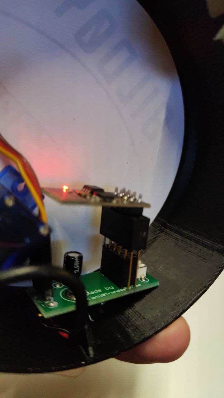
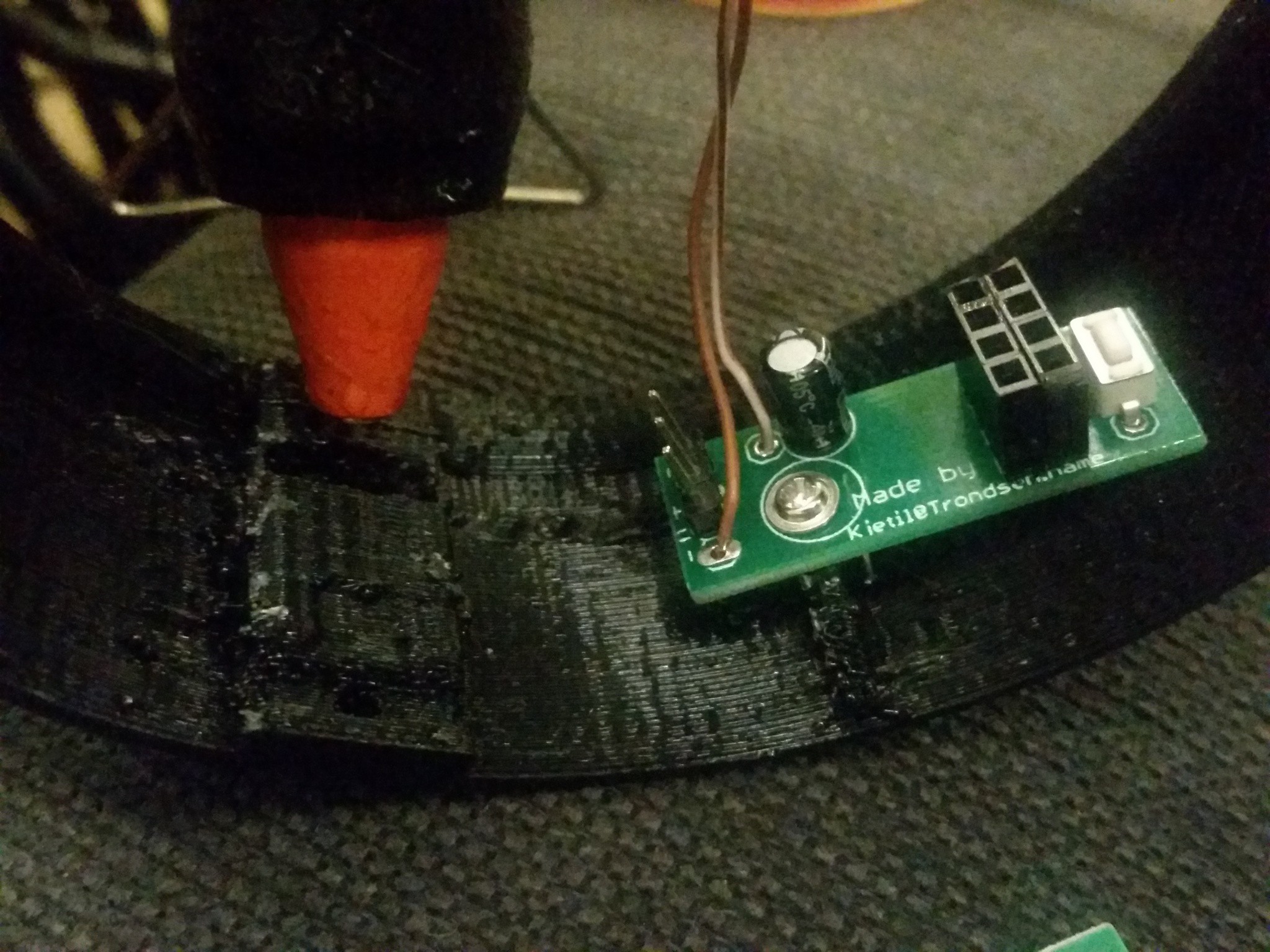
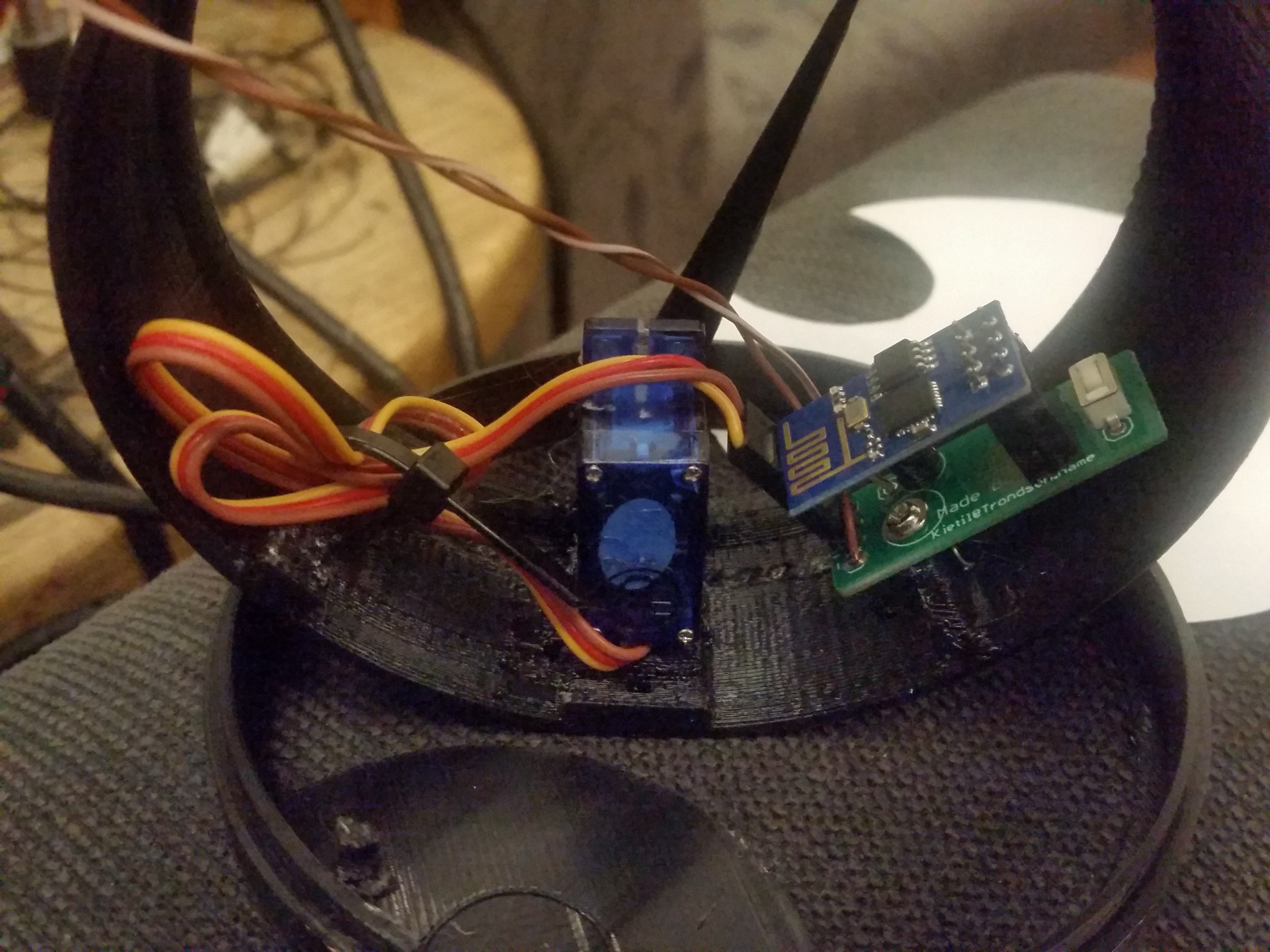
I found that the esp01 antenna was to close to the servo and cables. With a riser in the socket for the esp it became much more stable. (I did only have 1x6 high female pin header, but two did the trick.)
![]()
-
Mounting with PCB
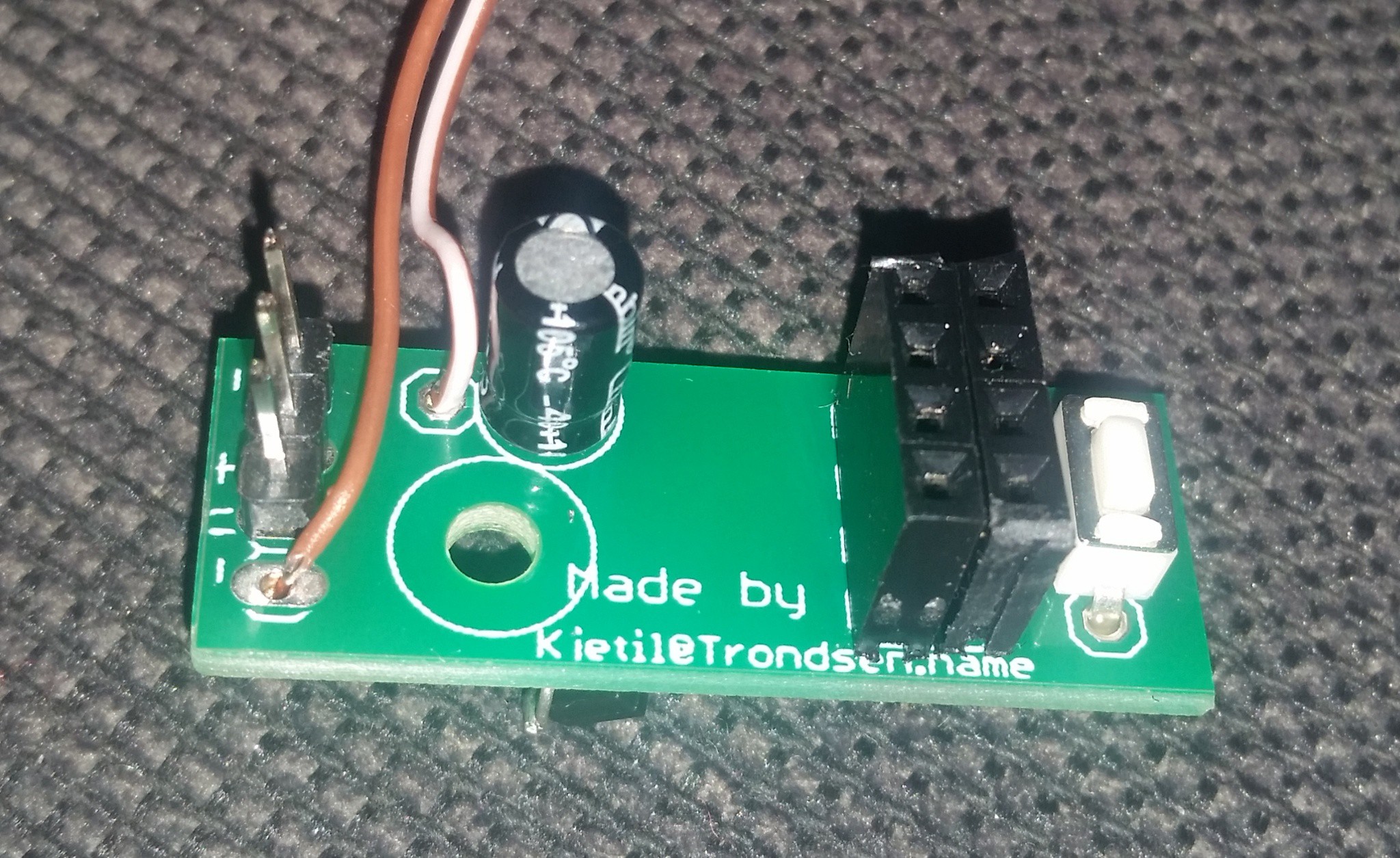
01/12/2018 at 17:11 • 0 commentsToday I got the PCBs I did design.
![]()
Here is the bottom side. The unused pads to the right is for the clock-project. The unused to the left is for a extra filtering capacitor if needed.
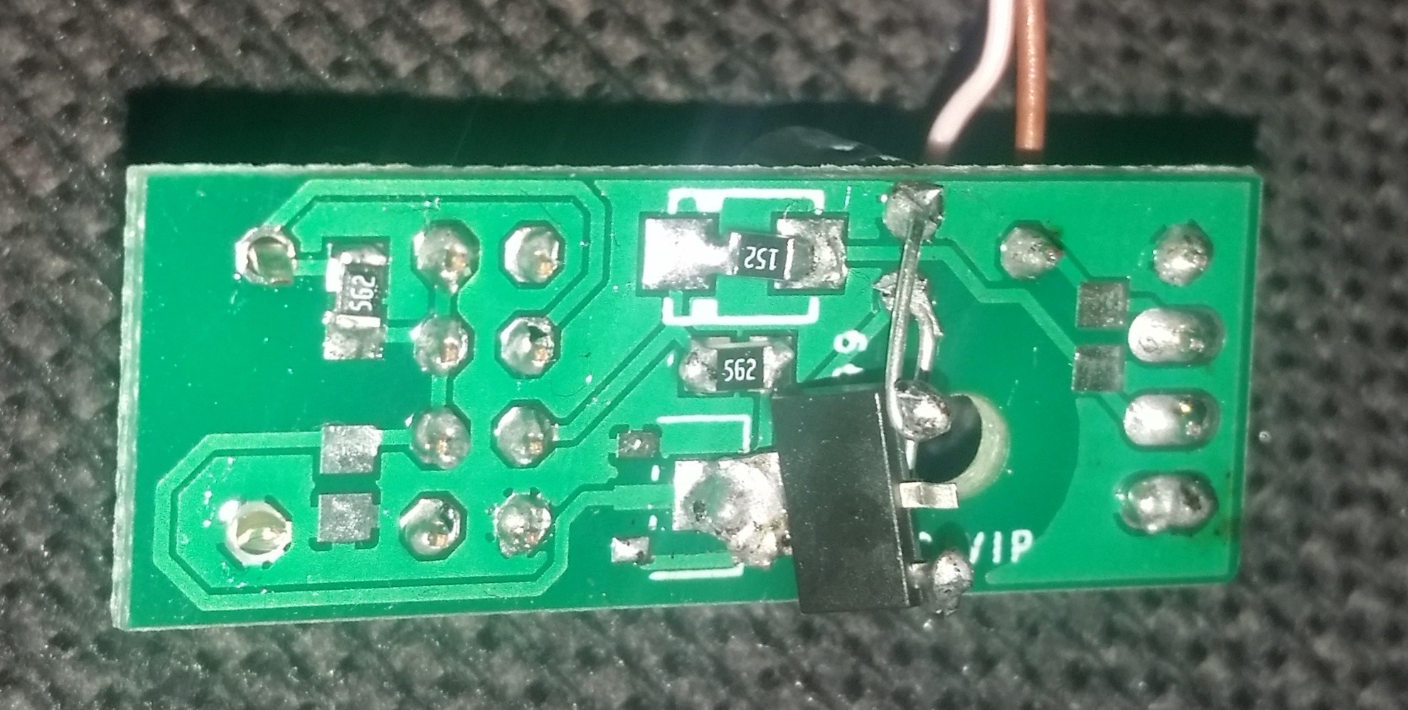
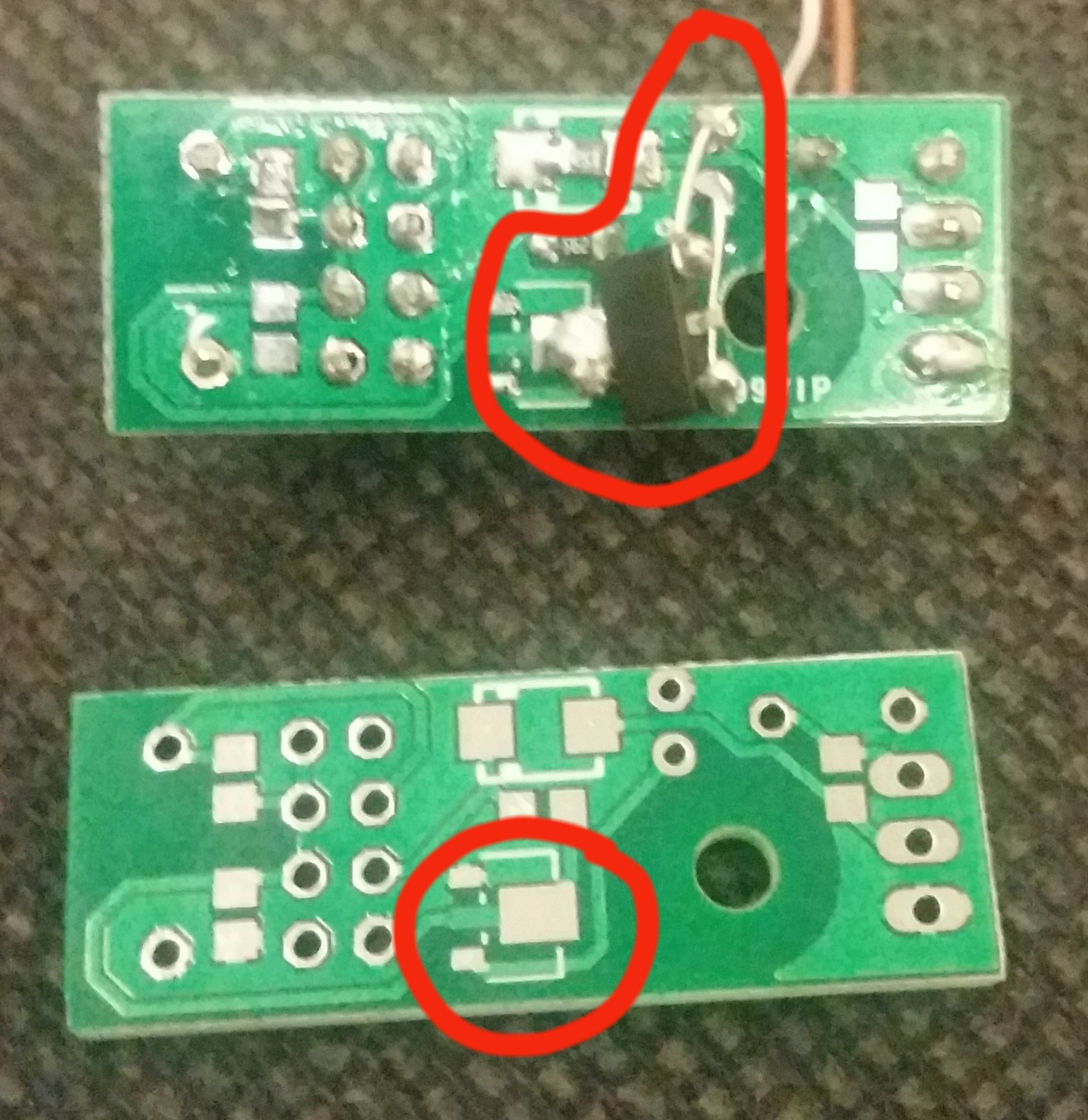
![]()
I found 2 errors in the design. the footprint for the resistor in the top center is a litle to big. It is marked as an diode because in the clock project it will be an diode. It was not a problem, but I will fix it in the design file. The other error was worse. I used wrong footprint for the voltage regulator. Not only that. But at the same time I used the pinout of the regulator i had, so there is no regulator fitting in the footprint with the pinout I used. The fix is marked in the image with red. Out on the regulator is soldered to the PCB, while the leads from the capacitor is soldered to gnd and in on the regulator.
![]()
Here the PCB is put in place in the enclosure. The screw used for mounting the PCB is the leftover from the servo. It comes with 2 screws, the other is used to fasten the needle. I fill the mounting hole for the servo with some hot glue before press fitting the servo.
![]()
After adding the ESP module and a cable tie to cleanup the inside looks like this.
![]()
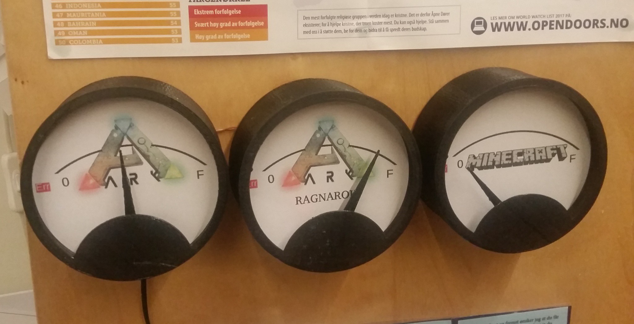
Normally you would have the power cable enter through the hole in the bottom and secure it on the inside, but in this particular case I just grab some power from the neighbor unit.And here they are. on the side of a bookshelf giving instant status of our servers.
![]()
I have also found an other error. The software needs to be a little more tolerant before marking Err on steam servers. I will update the software. but not today. New software and new design files for the PCB will be published sometime in next week.
-
PCB
01/01/2018 at 22:22 • 0 commentsDesigned and ordered a pcb for this project today.
Made the pcb so it also fits in the clock project. It is a small pcb, and to get it big enough to order i had to panelize.
Needed 4 pcs, 120 is soon on its way.... Prize almost the same. Realy hopes the design works.It is also designed with almost only bottom layer so it should be possible to etch at home.
Eagle design and gerbers will bee uploaded when it is werified working.
I might even try to sell some of the surpluss on ebay if anyone is interested. At least for europe it should be cheaper than ordering a new production....
Then it might be a week or two until arrival.
-
Mass production
12/29/2017 at 09:19 • 0 commentsOr not. But I have printed the second unit in one week.
Now i have one finished showing the status of our ARK server. I took the electronics from the old card box version and used it in this unit.
And the one I have printed now will show the status of our minecraft server. I will for this one design a pcb and document the electronics better along the process.
The project files are updated in the files section.
software now haves a #define MINECRAFT to switch between minecraft and steam server mode at compile time.
At startup the software also will do a full sweep with the needle. First a stop at the "err" marking, then a stop at "0" , then going to "F" or full and sweeping back to "0". if button on GPIO0 is pressed during this sweep, it will disconnect from wifi and startup the wifi access point for config. The AP is named MCViser. The config page is found at 192.168.4.1.
STL files for 3Dprinting is updated with tabs to ease the placing of the background paper and correct position of top and bottom parts of enclosure.
-
Software updates
12/27/2017 at 09:01 • 0 commentsI have been working with the software. It now successfully pings an ARK server. Minecraft is not forgotten - at the moment it is a compiler directive #define MINECRAFT, if it is commented out it compiles to ARK (and maybe other steam game servers, as it is a steam ping standard)
I decided to make a extra red spot far left on the display and point the indicator there if it could not connect to server.
I also made a little bigger step from zero to 1, to make it more clear that there is no one on the server.
The enclosure is finished printing, images will come.
Software will be uploaded when it is confirmed sort off stable...
But today it is car fixing time. Reality checks in.
-
Begun building second unit
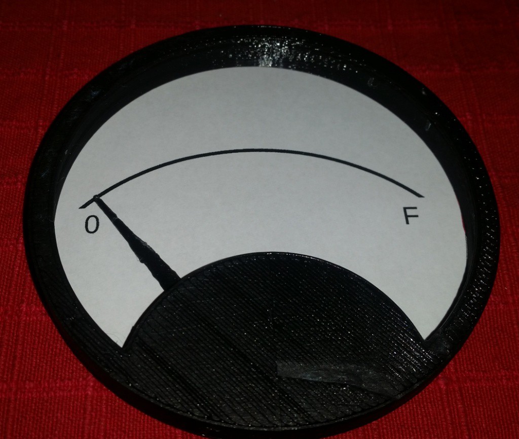
12/25/2017 at 21:54 • 0 commentsToday I begun building the second unit. I have printed the needle and the front frame. I have also made a new file with a simple background graphics for the gauge.
![]()
In the picture you could now see what it would be like. Only missing the bottom of the enclosure.
I have also done some testing with pinging an ARK Evolved server as my boys got that game for X-mas. Our server is up running, and the software for the gauge will bee updated to also handle the A2S_INFO query for valve games. The testing so far has only been done from a computer, but as it is a simple protocol it should be easy to implement.
Next time i have time I will print the rest of the enclosure, and work on the pcb.
-
Documenting project afterwards
11/21/2017 at 20:57 • 0 commentsAnd specially this one is a little bit tricky.
I do know i took some images, but i can not find them.
I have given away the first unit.
So this project is at the moment without pictures, but you may look at the stl files in a slicer and imagine the result....
But the end documentation might be better, because i will now build one more, and focus a bit more on the documentation when i do.
I will upload images after i have printed a new unit for our own wall. I will then also document the circuit board. At the moment the old one (the cardboard one in another project) is still doing a great job, so it may take a while before i get to make the new one - you know number two- a exact copy is a little more boring to make... .
Just uploaded the Arduino file and the stl design files so you can start building. I do know a lot of you are capable of finishing a project with less info that i have given you here :)
Minecraft server display ver 2
Updated standalone project to show the numbers of players on a Minecraft server without booting a computer