-
On hold :-(
02/15/2018 at 22:11 • 0 commentsI've to put the project on hold. Professional obligations (and baby) are taking all my time.
If someone wants to continu the project I can give help. Contact me.
-
Design files published
12/04/2017 at 20:55 • 0 commentsI just published design files. Schematic in PDF here in the file section, and complete Altium project on Github.
I'm currently getting quote for few boards to be manufactured. I will order in two weeks in order to get the prototype boards for early January.
If you have suggestion for improvement or correction, now is the time.
-
Can we call it Beta ?
12/02/2017 at 13:33 • 0 commentsPCB is finished, last time features where added :
- Power using only USB (obviously the amplifier will not work)
- Voltage measure of the external power supply thank to an ADC input on the touch screen controller
- Added test points with power supply to easily replace the LCD module
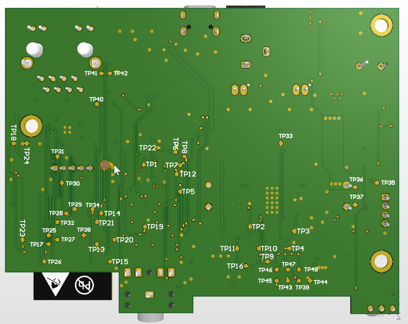
Speaking of test point here is the back side of the PCB :
![]()
The question is do I leave the test point denominator or do I replace them with signal names ? It could be problematic as the names will take a bigger area...
I need to clean the PCB and generate fabrication files. I'll try to publish files on github in the next few days.
After that documentation...
-
Alpha design
12/01/2017 at 11:14 • 0 commentsThe first Alpha design is done. I need to review it before publishing.
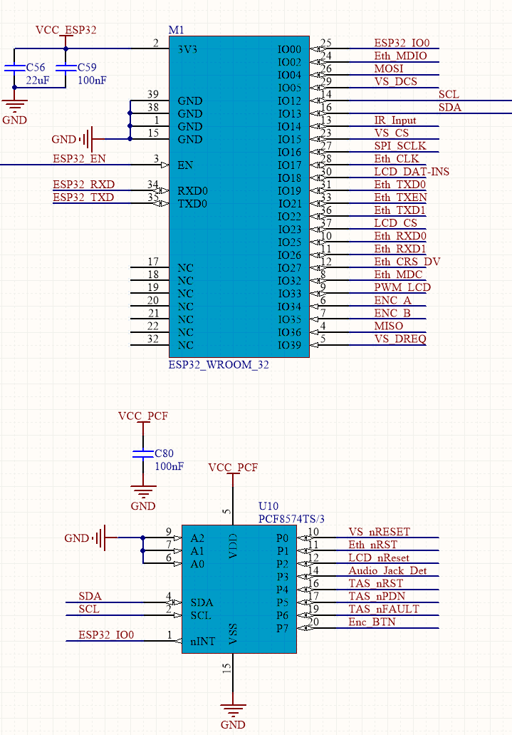
The limited amount of IO on ESP32 leads to use of an external I2C expander for slow control signals.
The pinout looks like this :
![]()
The ethernet PHY is clocked by ESP32, which prevent use of an external oscillator and associated circuit for not messing boot with IO0 level at start.
The rotary encoder is external to the board for an easier mechanical integration. Rotary signal are directly connected to ESP32, but the push button is on I2C expander.
IO0 is used as an interrupt input shared by I2C components.
USB update is through a CH340 with automatic reboot circuit.
KaRadio Wired
Integrated Karadio board based on ESP32 with VS1053 and embedded 2x15 ClassD amplifier

