Christoph Tack
-
RS Wedge mechanics
11/09/2021 at 18:47 • 0 commentsLocation of the wedge
The internals of the Robosapien leave little room to add PCB's inside the housing. There's some room in the back around the speaker, but it's hard to connect the micro-USB connection from there.
The upper leg parts leave enough room for the PCB and make it quite easy to allow connection for micro-USB and audio.
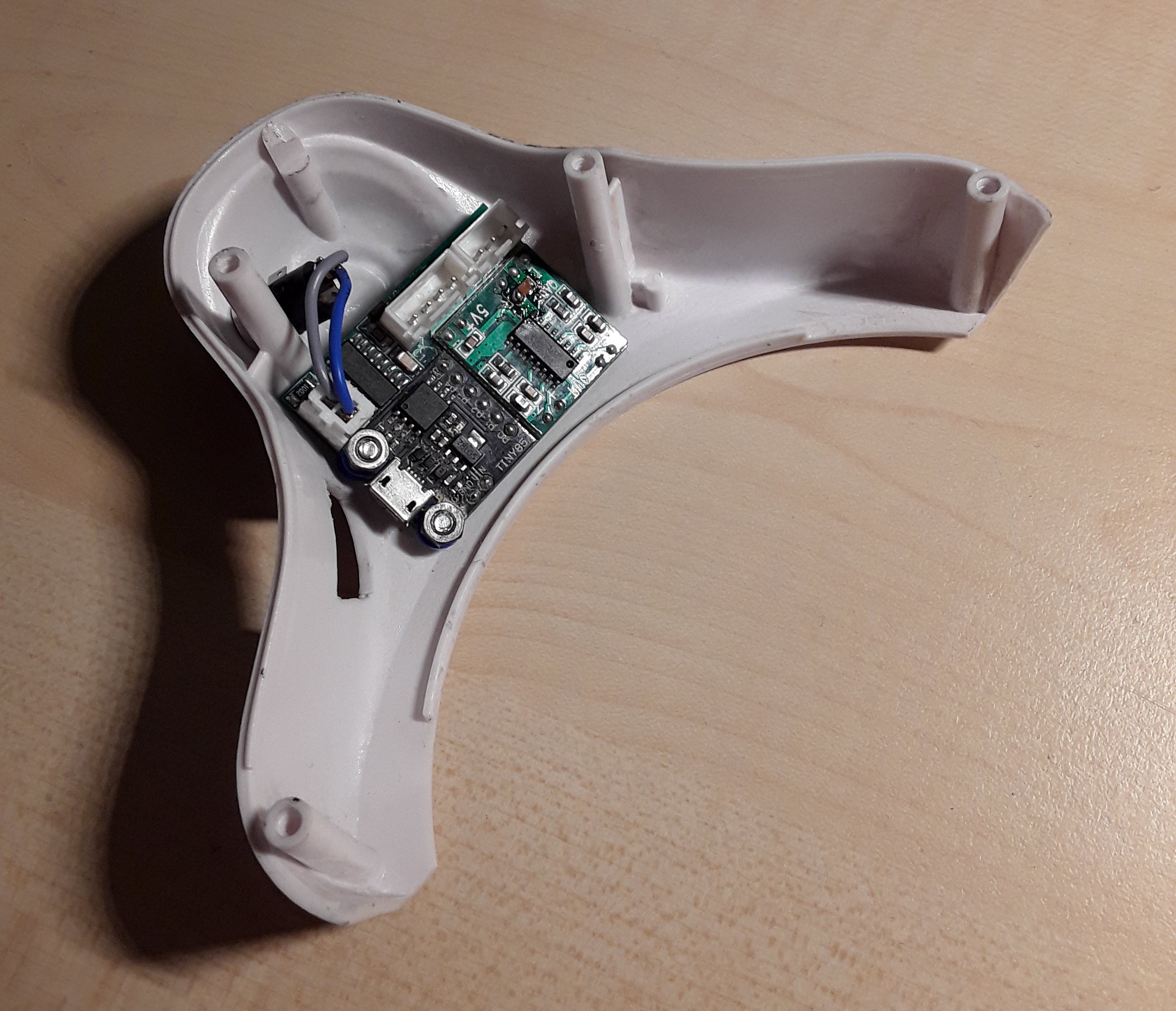
My original idea was to put the PCB (design in EasyEDA). In the upper right leg. Unfortunately the JST-XH connector are too high. It's a pity that I'd made a cutout in the upper right leg before realizing that.
Either I could redesign the PCB, moving the connectors to the top edge, or I could mount the PCB 180° rotated in the upper left leg. I went for the second option. The fit is less ideal. Because the USB-connector is mounted lower, a bigger cutout in the leg is needed. The USB-connector also rubs internally against the lower left leg, sometimes causing unreliable connection. Maybe I'll fix that in the next PCB revision.
RS Wedge mounted in upper leg
As can be seen in the picture below, it would have been more practical to have the USB-connector where the 2-pins JST XH-connector is located now. Component higher than 2mm must be avoided along the lower half of the PCB.
![]()
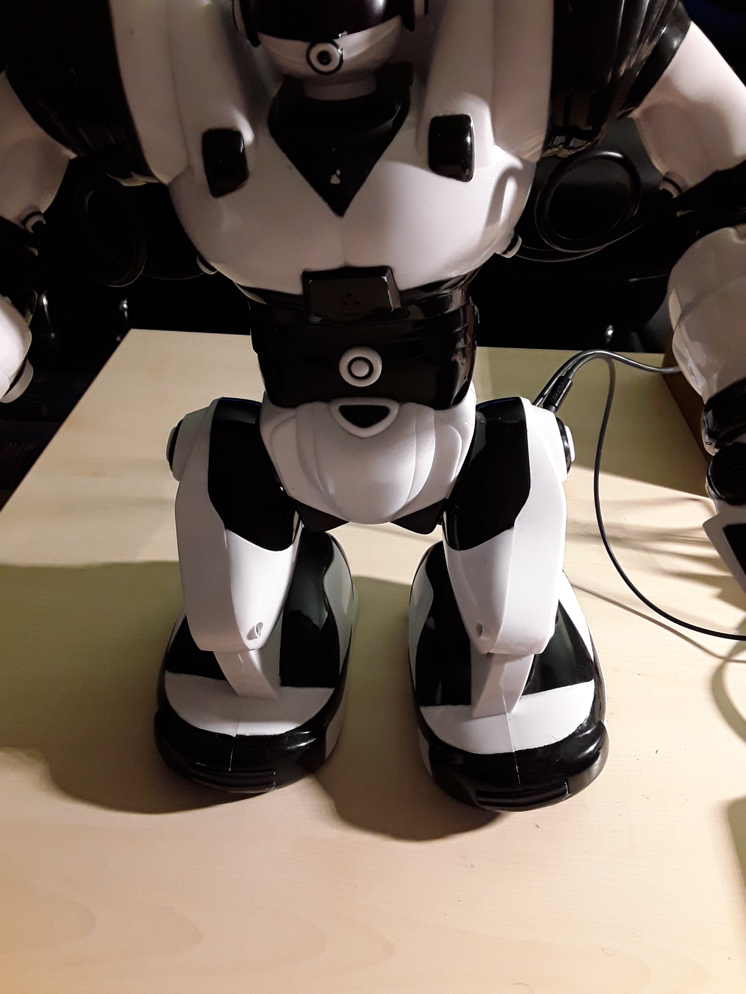
PCB mounted in upper part of left leg Mounting done
![]()
Connected audio and micro-USB to left leg ![]()
Detail of left leg -
References
10/29/2021 at 17:01 • 0 commentsTechnical documentation
Using Raspberry Pi as controller
-
Text to Speech
07/31/2020 at 13:32 • 0 commentsInstallation
in Ubuntu
sudo apt install libttspico-utils soxConvert text to speech
pico2wave -w lookdave.wav "Look Dave, I can see you're really upset about this."Speech playback
Using aplay
aplay lookdave.wav
Playing WAVE 'lookdave.wav' : Signed 16 bit Little Endian, Rate 16000 Hz, Mono
Using play
play -qV0 lookdave.wav treble 24 gain -l 6Adding speech effects
The following command will convert the female voice to a robot voice.
play lookdave.wav stretch 1.2 133.33 lin 0.2 0.4 echo 0.4 0.8 15 0.8 synth sine fmod 30 echo 0.8 0.8 29 0.8 play WARN alsa: can't encode 0-bit Unknown or not applicable lookdave.wav: File Size: 119k Bit Rate: 256k Encoding: Signed PCM Channels: 1 @ 16-bit Samplerate: 16000Hz Replaygain: off Duration: 00:00:03.72 play WARN echo: echo: warning >>> gain-out can cause saturation of output <<< In:100% 00:00:03.72 [00:00:00.00] Out:72.0k [ | ] Clip:0 Done. -
RS Wedge firmware
04/10/2018 at 19:51 • 0 commentsThe firmware for the RS Wedge can be found on GitHub.
Communication PC → RS Wedge : CLI
To enable easy interfacing for humans as well as machines, a command line interface has been used. The Arduino-CommandLine library has been used.
Below you can find a capture of a command line session with the RoboSapien:
Welcome to minicom 2.7

OPTIONS: I18n
Compiled on Feb  7 2016, 13:37:27.
Port /dev/ttyACM0, 18:02:16

Press CTRL-A Z for help on special keys

>
> action 196
> action 197
> action 198
> audio 0
> action 198
> action 197
> action 197
> action 196
> action 195
> audio 1
>
Commands
Two commands are implemented "action" and "audio".
The "action" command executes one of the Robosapien standard actions. On a standard Robosapien, you would have used the remote to start these actions. A list of actions can be found in the source code of the RS wedge.
The "audio" command switches the Robosapien's audio source : "0" selects the audio jack as source, which allows the connected laptop to route speech or music to the Robosapien. "1" selects the Robosapien controller as source.
Communication RS Wedge → Robosapien : IR protocol
The easiest way to probe the original protocol is at the back of the main board, at the connector named "HEAD". Remove this PCB, solder your probes to "GND" (black wire of "HEAD"-connector) and "IROUT" (white wire of "HEAD"-connector).
![]()
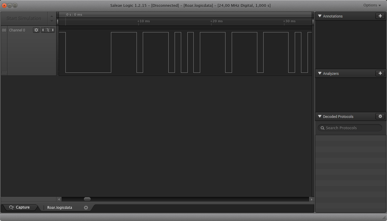
The IR-protocol is quite simple. The default state of the IR-OUT signal is high. The message starts with a low pulse that lasts 6.26ms and is followed by databits 7 downto 0.
- 0-bit = 0.843ms H + 0.843ms L
- 1-bit = 3.512ms H + 0.843ms L
Using this information, you should be able to figure out that the screen capture shows the 0xCE command.
According to Aibohack, the protocol uses 1200baud. I noticed quite a lot of jitter between bits. Pulses of 909ms wide are not uncommon.
Keeping the Robosapien awake
- 5 minutes after startup, the Robosapien goes to sleep. In sleep mode, no commands can be executed. The "WAKE UP" must be sent to wake the unit up. The Robosapien's wake-up routine is the same as when you power it up. It's quite noisy. You don't want to do this more than once a day.
- Robosapien's manual : "After approx. 2 hours of uninterrupted sleep, he'll power himself off to save energy".
Question: "How to keep the Robosapiens on indefinitely while keeping it still & quiet?"
Answer: Sending 0xEF once a minute keeps the Robosapiens on.
-
RS wedge hardware
04/10/2018 at 18:56 • 0 commentsBlock diagram
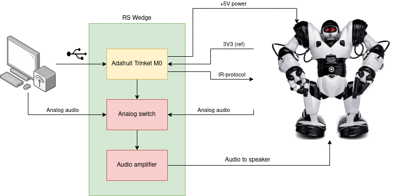
The original Digistump Wedge has been replaced by an Adafruit Trinket M0 because the USB-connection with the Digistump didn't work reliably.
![]()
Wedge mounted between computer and Robosapien The RS Wedge has two functions:
- Converting commands from the PC to the IR-protocol that the Robosapien understands.
- Control an analog switch to select the Robosapien's speaker output between the PC-audio or the Robosapien internal audio.
Electrical details
Microcontroller
To reduce the development time, a development has been chosen. The Digistump clone has been selected in the end. It has mounting holes, is small and contains a USB-connector.
Audio output
To be able to use the internal sound of the Robosapien as well as audio from the PC on the Robosapien's speaker, an analog switch is needed.
The 74HC4053 will be used. It's cheap and easily available. Its three internal channels are connected in parallel. In this application it doesn't matter much, but it decreases the series resistance of the multiplexer.
The audio from the laptop is too weak to connect directly to the Robosapien's speaker, so we'll use an audio amplifier. The PAM8403 is available on a PCB with the necessary peripheral circuitry. These modules only cost a few cents. The audio amplifier is connected at the output of the multiplexer.
The audio output of the Robosapien can be taken from C13A. This output is connected to a 10/2K2 voltage divider, which is connected to the analog multiplexer. Decreasing the Robosapien to 1/6th of the original level is needed to avoid oversteering the amplifier.
Finally the Digistump controls the state of the analog multiplexer, choosing between PC audio and Robosapien audio for the Robosapien speaker.
Wiring to Robosapien main board

3 wires soldered to Robosapien main board. GND (yellow), IR-OUT (brown), VCC(red) is the internal 3V3 supply of the Robosapien. It's used as a reference voltage for IROUT-logic signals. -
Audio connection on PC side
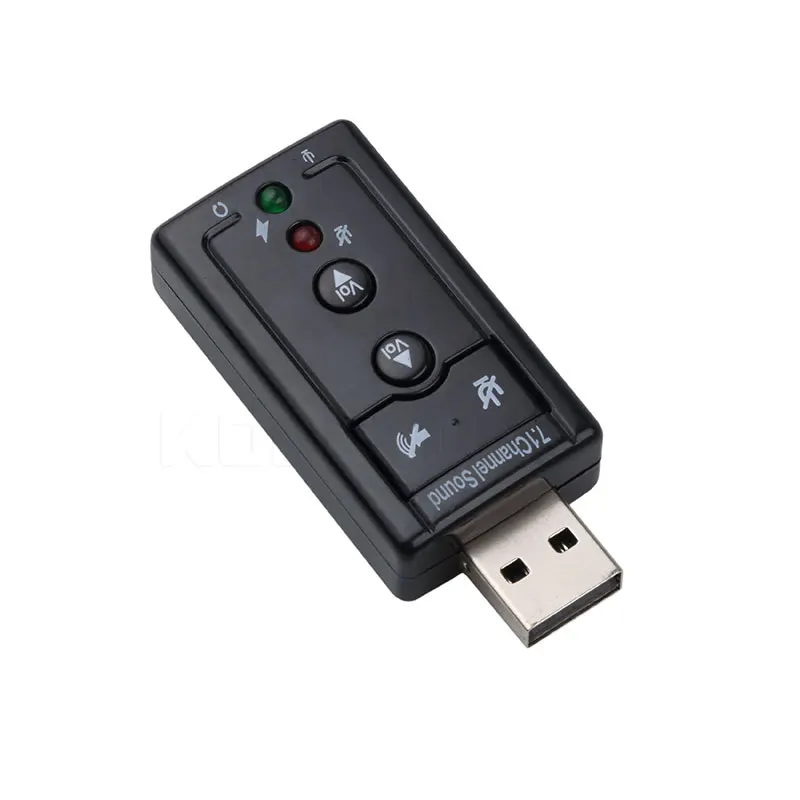
02/23/2018 at 19:59 • 0 commentsIn the final application, a BeagleBone Black (BBB) will be used to control the Robosapien. Having one in my drawer is the only reason for using a BBB. It unfortunately doesn't have an analog audio interface.
Adding an external USB-Audio interface is a cheap (<€1) and easy solution. It's supported by default in Ubuntu Linux. The audio chipset is from Generalplus. There's no more specific data. I think it's either the GPD8102B or GPD8106B under the blob.
![]()
AliExpress USB Audio interface Unluckily, in an attempt to cut down costs, the manufacturer has also cut down on specifications. The audio output lacks low frequencies, which makes it very annoying to listen to. Opening up the unit reveals that the audio is capacitively coupled. This coupling capacitor forms a high pass filter with the input impedance of the headphones. This device is cheap. The capacitor is too small. The cutoff frequency is too high, cutting off lower frequencies from the headphones. Luckily, there's an easy fix:
- Open up the USB-audio interface. Easiest way: drop it from 1m on a concrete floor. For whatever reason (probably cost again) the housing is not glued.
- On the bottom you'l find C8 & C9. These two 0805 caps are 10µF.
- Replace these caps with 22µF or higher value. Higher cap values in small values are relatively expensive. It's clear why they tried to save cost here.
- Normally, you should be able to assemble it without problems.
- MIC-IN :
- TIP + RING = MIC-IN
- SLEEVE = GND
- AUDIO-OUT :
- TIP = left
- RING = right
- SLEEVE = GND
-
Legacy : Getting started with Digistump clone
02/16/2018 at 21:11 • 0 comments2021 Update : Dump the Digistump
As Adafruit also remarked for its Protrinket 3V: the bitbang USB technique doesn't work as well as in 2014. The Digistump still works when directly connected to my Thinkpad laptop (on Linux), but not when connected through a USB-hub. On Windows, it doesn't work at all.
So another platform will be needed with native USB. I think of the Adafruit Trinket M0 or the Seeeduino XIAO. The annoying thing is that the Robosapien wedge is mounted using the mounting holes of the Digistump. We'll have to fix that.
For your reference, the historical Digistump info can be found here below.
Where to buy?
- Digispark website
- AliExpress
- This clone has two mounting holes, which is an advantage over the original Digistump.
- The LED is on P1, not on P0.
Installation
Follow the instructions on:
- Connecting and Programming Your Digispark (to install the Digispark Board Manager URL)
- Linux troubleshooting (to fix the udev rules)
Programming
The Digistump clone is shipped with a functioning bootloader.
To program the application: first click verify, after that power on the Digistump.
Further reading
Marcus Jenkins wrote an interesting tips & tricks to get you started with the Digistump clone.
Use a USB hub with a power switch for every outgoing USB port. As such you can easiliy reprogram the Digistump without having you to replug it to the USB-port every time.
The schematic can be found here.
USB CDC Robosapien V1
Robosapien's actions controlled through a virtual USB port. Speaker switchable between Robosapien & external audio jack