RoboMonkey
-
Final Entry
02/07/2018 at 13:02 • 0 comments2 Units are complete and testing. I wish I had the firmware to run them at 4800 baud, but I'm stuck at 300. Makes the response time slower than I'd like. My colleague (and chief engineer) is satisfied with the modification and reminds me that it's that slow on the 4 wire too. I know it is, but being the perfectionist I tend to be, I want to crank this puppy to 11.
He also suggested I do a write up for Broadcast Magazine. Wonder how the submission process works....
If it's useful to you for Radio control or anything else that uses 4 wire, let me know. Leave me some skulls man! :)
-
Serial to Ethernet, using the Comtrol DeviceMaster
12/07/2017 at 17:49 • 0 commentsSo, once I had the serial to the proper level, I ran the units back to back with a null modem cable. SUCCESS! The 300 baud data stream did exactly what it was designed to do.
Newer versions of the ARC-16 can go as high as 4800 baud. But my lowest speed unit is at 300 and it limits what other devices can use for rate. These things used to run at 110 Baud, just so you have an idea about speed that was considered workable for control of Radio Transmitters.
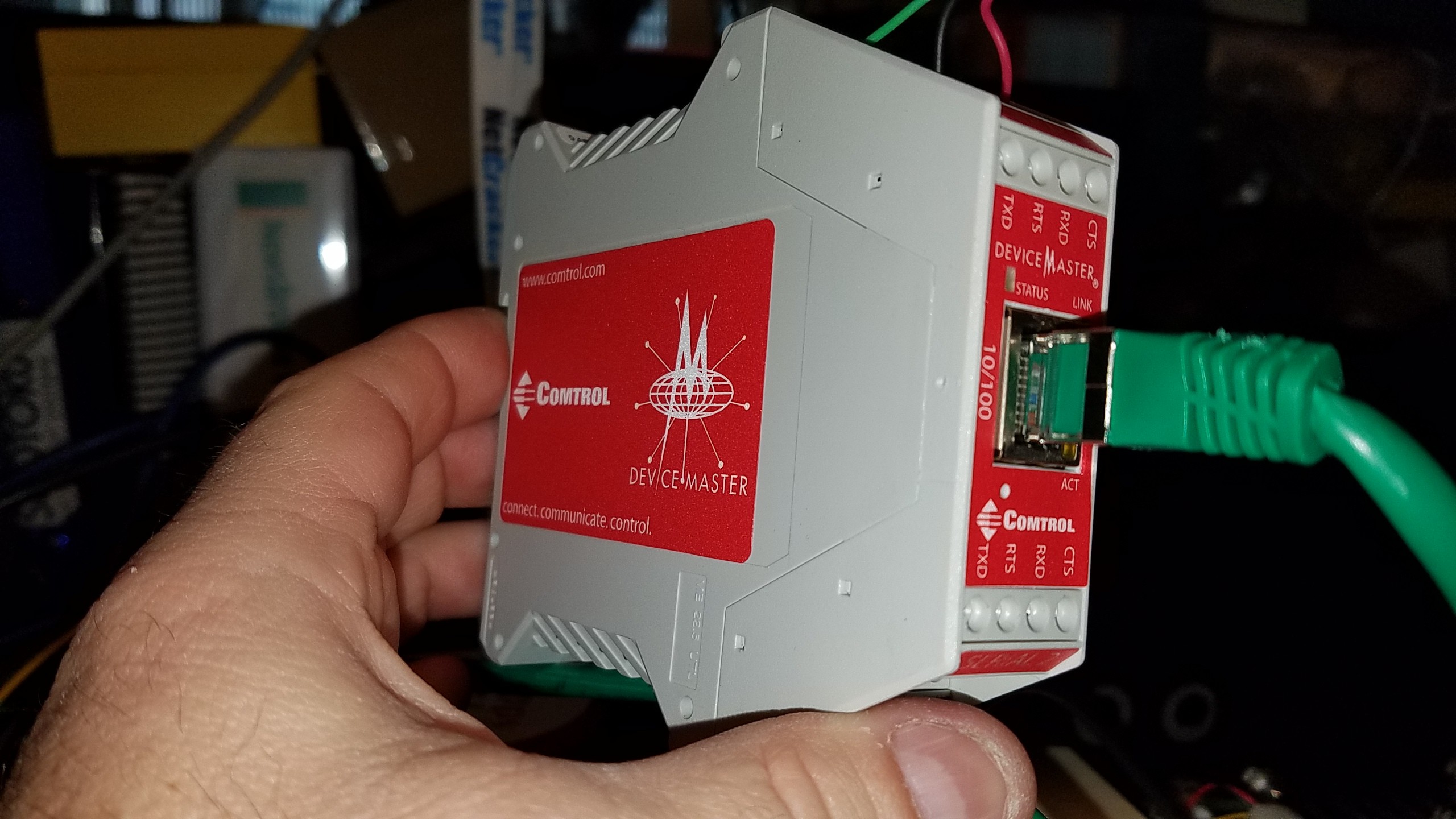
Now came the time to use my trusty serial to IP converter to make this thing continue to operate in the modern world we live in.
![]()
I've already written up the Comtrol Devicemaster on another project. I know there are less expensive options available, but I've never had a lick of trouble with these. When doing diagnostics for what's wrong with a service or "where's the data?" these things have a web interface that make it very easy to find out what is the issue.
Wash, rinse, repeat. One on each box. Then test. No trouble at all in the 24 hour test on my bench.
![]()
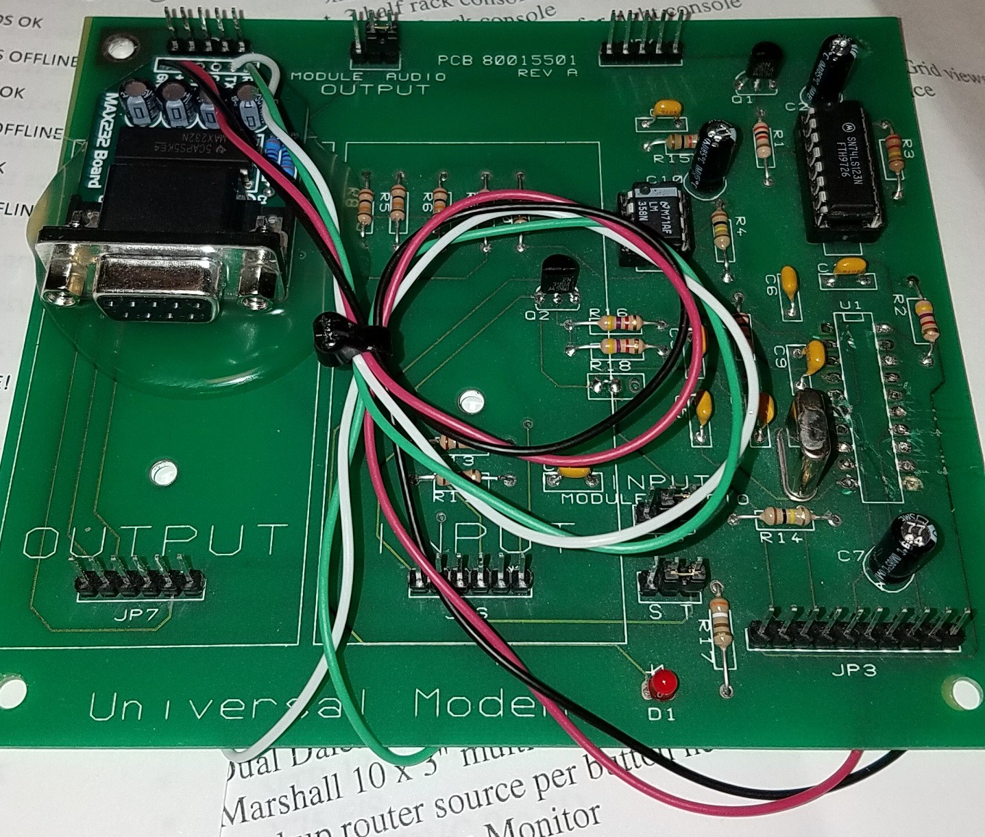
One last thing. The centralized unit that is to operate at our main studio has 2 modem boards. This is the Gen 2 of the wiring. Why do Gen 2? Well, thanks to a desoldering iron that wanted to go stupid, I couldn't get the chip socket out properly and decided to source the wires from other places on the board. I realize I could avoid the board altogether since JP3 holds all the data lines I require, but I'm trying to keep things neat with the MAX 3232 board, and the hot glue doesnt' hold to the painted case as well as it does to PC board.
That's it. Feel free to comment.
-
Get out your Scope probes, find your purpose...
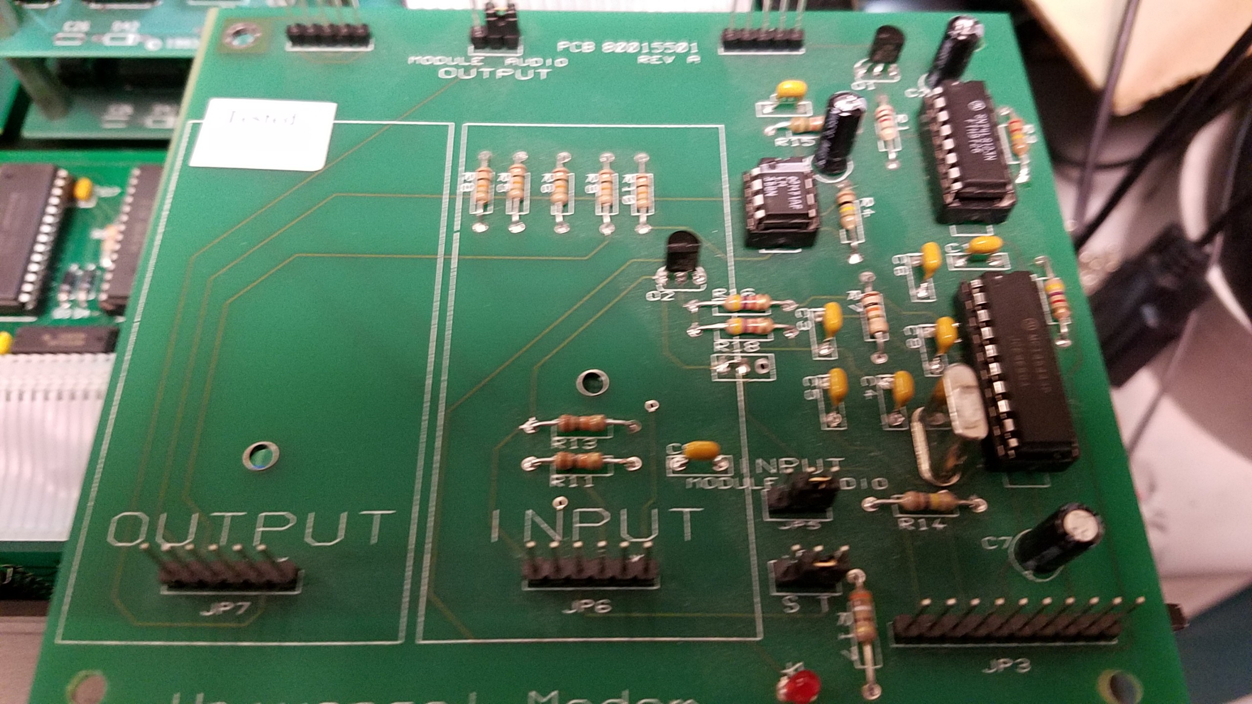
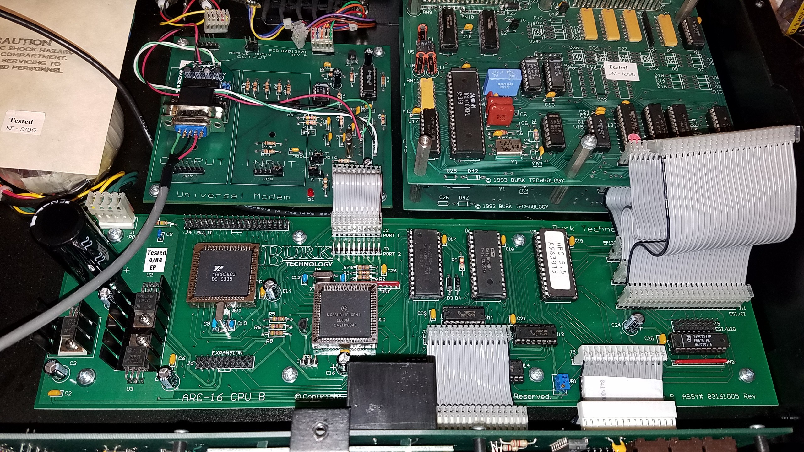
12/06/2017 at 23:42 • 0 commentsMuch of the hardware was well labelled. Lacking a schematic I simply began an inventory of the socketed chips.
![]()
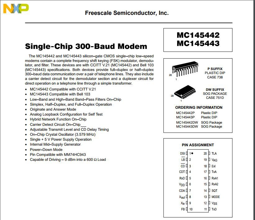
The 20 pin next to the crystal is a modem chip. Part MC145443P. UART enters this chip and it's modulated for the 4 wire Analog.
![]()
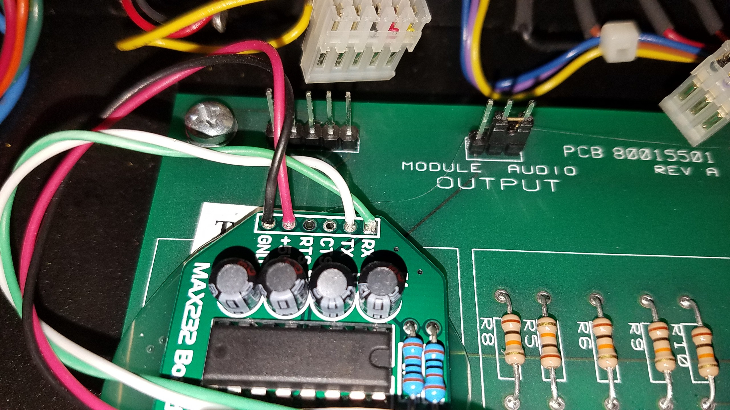
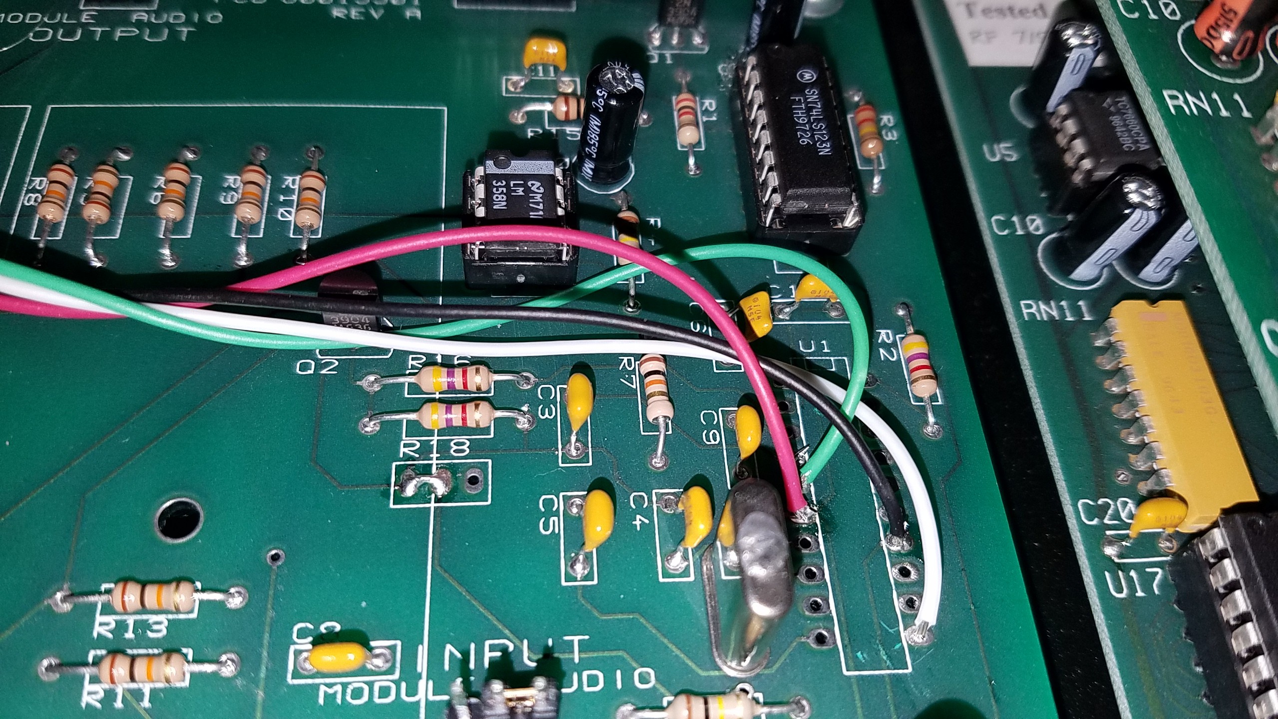
Pin 5, 6, 11, and 12 will do the trick. I'm removing the chip and using the 5 VDC to run the level shifter, the ground and RxD and TxD pins will round out what we really need to communicate.
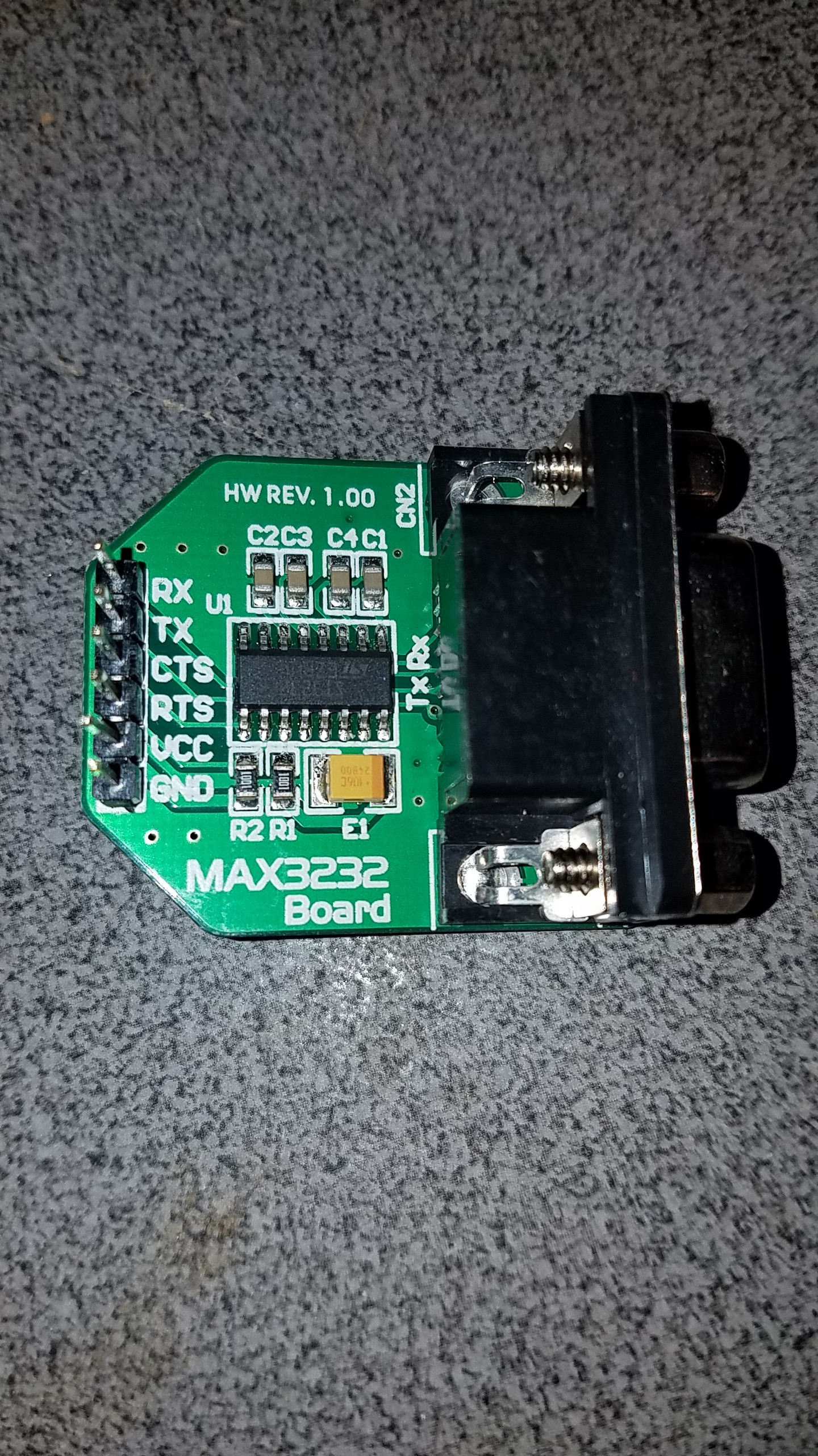
Now the levels aren't enough to trigger the signaling on the Comtrol devicemaster. I'm using a MAX3232 board for the level shifting. At $10 or less each, they save a lot of guess work in rolling your own.
![]()
I removed the socket from under the chip and just soldered in the wires where needed.
![]()
![]()
Noticing that pin 14 was also a ground point and a jumper was in use under the board to make the connection to pin 12, I used 14 in my wiring and removed the modification by the manufacturer.
Had a problem building the second unit where I had swapped the ground and 5V lines. I fixed that but then ended up with only TX working, no RX. Went through long diagnostics to determine where I had gone wrong or blown up. Turns out in the reset of the wires to their proper positions I left the iron on too long and ended up shorting out the 5V and RX lines together. This short was where the wire had melted and come together. If I hadn't been ready to scrap all the wiring and begin again I'd have never found it. (Fail of the week? Took me about a week of small time snippets to find it. Note this isn't my primary job to convert this, so I got maybe 30 minutes every 3 hours or so to dig into this.)
A bit of hot glue to secure the Max 3232 board and we're in business.
![]()
-
Where to begin?
12/06/2017 at 23:27 • 0 commentsSo, while I knew that 4 wire really just used the old UART signaling to operate, with modulation added, it was a simple case of finding the UART TX and RX lines.
Luckily the old radio guys who designed this enjoyed using dedicated chips. Aside from the technical ease of using these types of ICs, the dedicated chips also were less prone to radio noise in a high RF environment.
Reviving a 4 wire communication system
Convert Burk Radio Remote Control from 4 Wire control to Ethernet using Comtrol adapters