-
CNC'ing a motor mount - Brushless motor upgrade part 2
11/10/2019 at 15:08 • 0 comments![]()
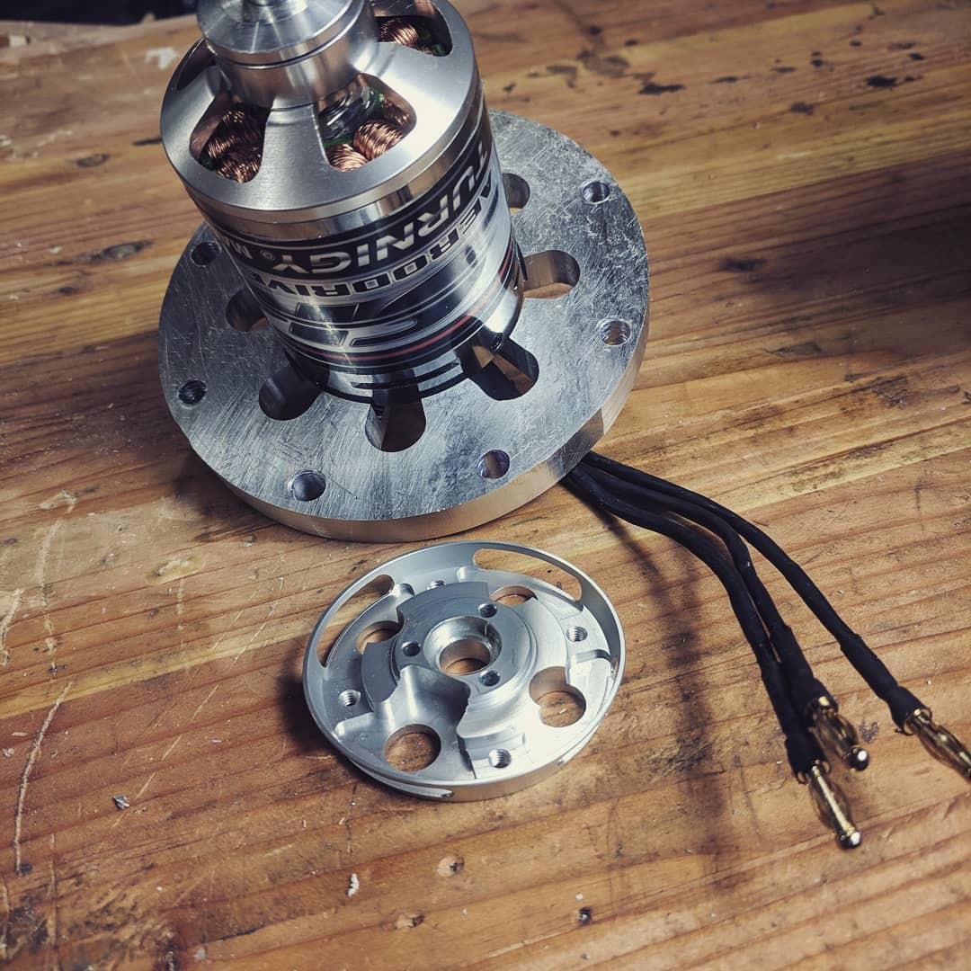
Playing around with CNC! After building the housing assembly for the motor, I needed to mount the motor itself. The motor came with a small bracket, but that didn't sound like much fun. Instead, I took off the top of the motor can and replicated the features in CAD. I then milled that directly into the top housing plate with the little baby Taig CNC mill.
Everything worked remarkably well, only a few hiccups. Coolant also worked a lot better than expected. Unfortunately, an error in my program meant the air vent slots didn't get fully machined so the coolant didn't drain, making it hard to see what was happening.
-
Upgrading to a BLDC motor
05/01/2019 at 20:33 • 0 comments
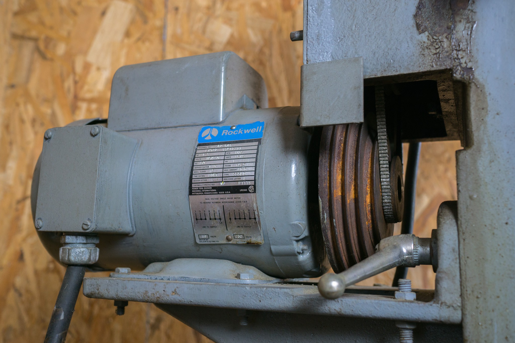
I recently decided to upgrade the motor on my Rockwell mill. The existing motor is a 3/4hp induction motor and it's OK... but has a bent shaft and mismatched step pulley. I'm upgrading the motor to use a 4kW brushless hobby motor, which is roughly 5hp peak. Realistically, I expect around 1kW continuous (1-1/3hp). I chose a BLDC over VFD induction drive because A) I had the motor on hand, B) they are generally more efficient and power dense...and C) brushless motors are fun :)In this first part I mill out the motor mounting plates and struggle to drill/tap some stainless pipe. Many broken taps and drills later I have the mount roughed out, ready to start mounting electronics.
The motor is a 192kv Turnigy Aerodrive brushless hobby BLDC. Rated for 48v and 4kW, it's max speed is ~9000 RPM according to the manufacturer. After running the numbers, it likely comes out a bit closer to 2600W and 7300 RPM.
BLDC torque is theoretically around 3.5 Nm, while the original induction motor is near 2.3 Nm. So it should, theoretically, be a bit more torque in a smaller package even after a healthy de-rating of the manufacturer specs
-
Installing a Digital Readout
05/17/2018 at 20:49 • 0 commentsI recently added a digital readout to the mill. A few hiccups along the way, but overall the installation went very well. The DRO is a kit from TouchDRO. Ordered the PCB and components, soldered it up and fabricated some mounts for cheap Shars scales.
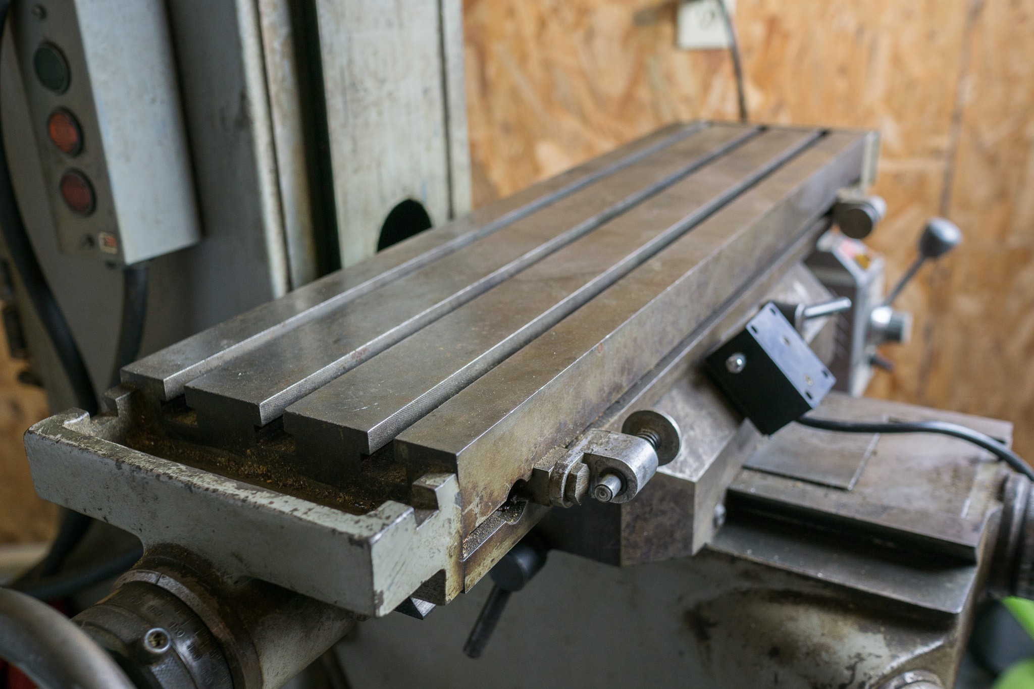
After calibration, the DRO reads +/- 1.5 thousandths of an inch, which is right about the tolerance of the scales according to the manufacturer.
-
Painting and re-assembling the mill
04/18/2018 at 15:09 • 0 commentsPart four is up!
In this last episode, I paint all the parts and re-assemble. There is also a digression into the power-feed adapter, since I got some interest on how it was put together. Looks like someone fabricated a custom adapter to mount a Central Machinery (e.g. Harbor Freight) power-feed onto the mill.
Thanks all for watching! Time to start on "real" projects now that the mill is up and running :)
-
Cleaning and stoning the table
01/05/2018 at 22:33 • 0 commentsTook a bit of wrestling with the mill, but I removed the table and lead screw. Wasn't completely necessary, but it made cleaning up the table surface a lot easier. Degreased everything, evapo-rusted the surface, then lightly stoned out the burs.
Also cleaned and stripped the mill body, and got it masked up for painting. Nearly done! -
Cleaning fiddly bits and fighting snap rings
12/15/2017 at 17:40 • 0 commentsPart two is up! This episode is mostly cleaning the quill fine-feed control, the head rotation mechanism, cleaning the bearings and wrestling with the pulleys.
One interesting thing I found was the worm wheel in the head rotation mechanism. This mechanism allows you to tilt the head left/right, so that you can make angled cuts. You adjust the tilt by turning a nut, which internally rotates a worm against a worm wheel.
What's interesting is that the worm wheel is made out of aluminum, while the worm gear itself is steel. The worm wheel is the piece that takes any rotational forces induced by the cutting action (assuming the force is too large for the locking bolts). So there is a chance of shearing or mangling the aluminum teeth if the head takes sufficient sideward load.
I'm unsure why Rockwell chose to make this gear aluminum... perhaps it's a sacrificial part? If something goes wrong, you'd rather destroy the worm wheel and replace, rather than the worm gear? Not sure.
In any case, I'm expecting one more video in this series; stoning the table, masking everything, priming/painting and then re-assembly. There may be a followup video with things like installing DRO, etc.
-
Milling some metal then head disassembly
12/09/2017 at 15:56 • 0 commentsI normally just document projects with photos, but for this mill I thought it'd be fun to try my hand at video. So here's the first episode:
I give a quick tour of the machine, play around with milling some scrap metal, then start disassembling the head, spindle/quill and ram. Next episode will be mostly disassembly and cleaning: need to do the bearings, fine feed control, table, and the body itself.
Let me know what you think of the video! First time editing something like that together :)
-
Overview of the mill
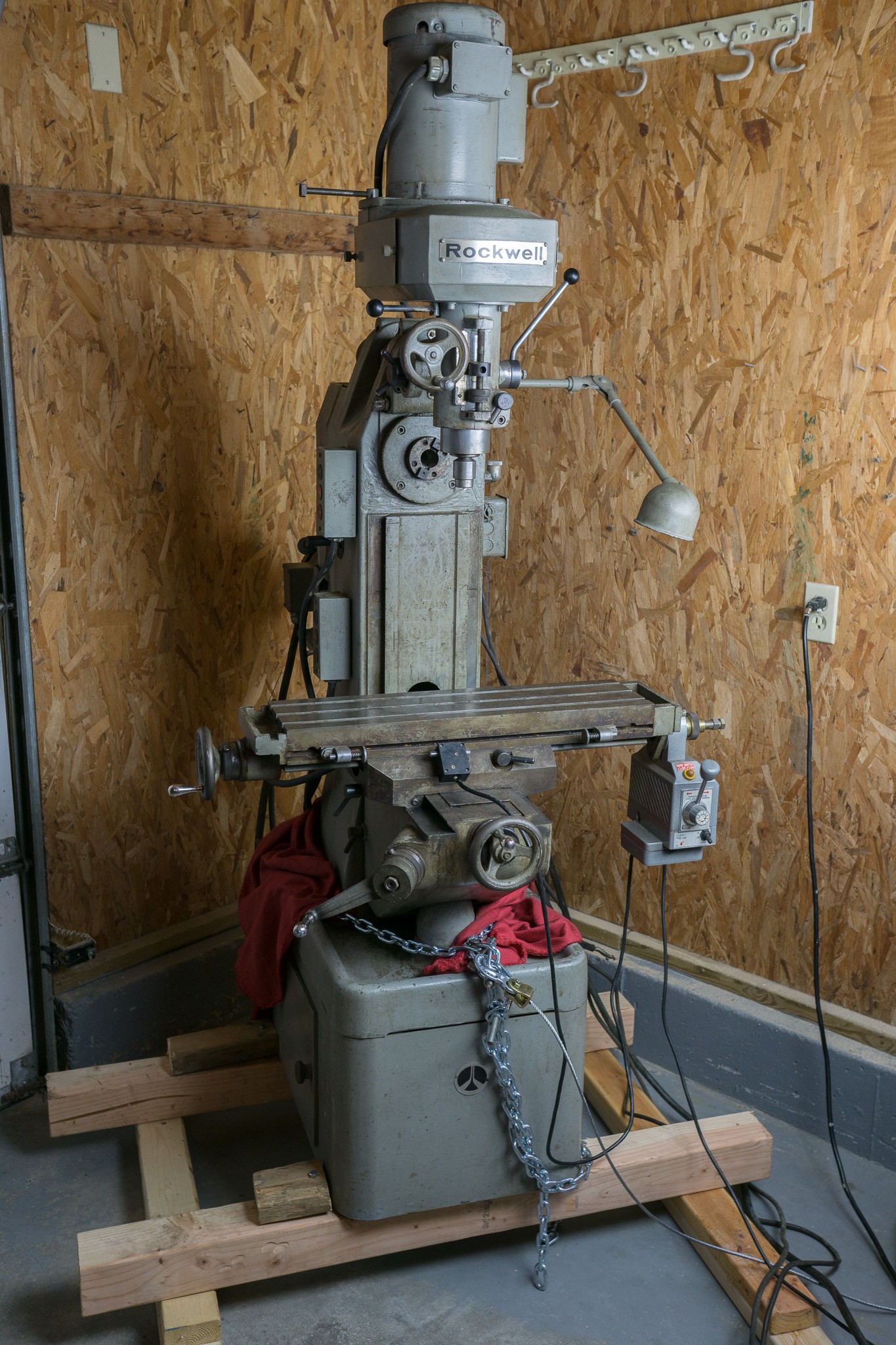
12/09/2017 at 02:02 • 0 commentsI recently acquired this Rockwell 21-122 Horizontal/Vertical milling machine from my local Craigslist.
![]() ---------- more ----------
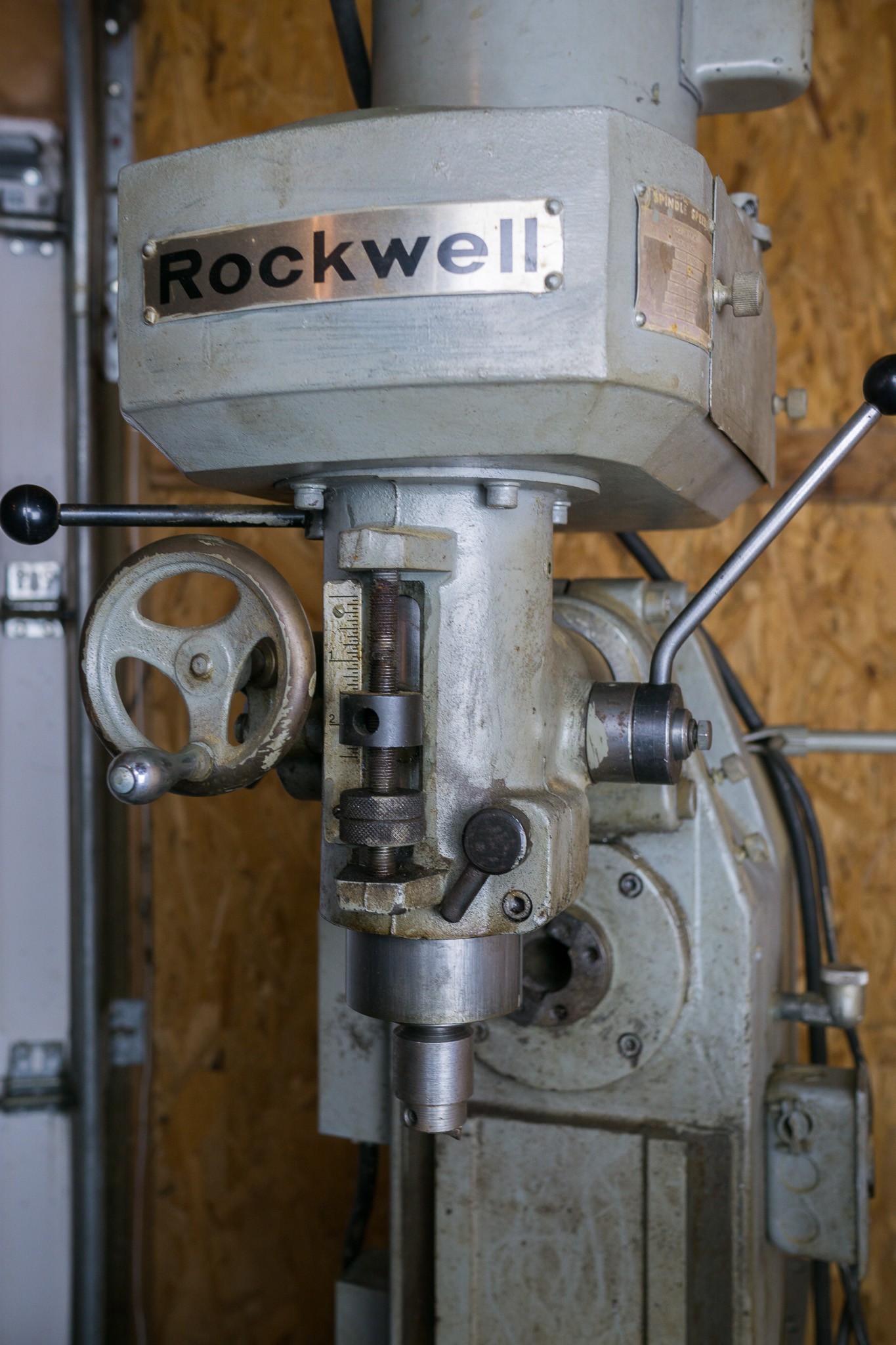
---------- more ----------It’s in remarkably good shape; most of the moving parts are free, the ways look very clean, the table surface is relatively free from dings and not a whole of obvious rust. The quill doesn’t have full travel though. It can only actuate from 1" to 2.5" … it can’t fully retract inside the spindle.
![]()
The bearings also feel a bit rough. Given the overall good health of the machine, I’m thinking it’s just old, dried up grease. These RWs don’t have an oil reservoir system for the spindle, so the bearings are just packed with grease. It looks like this mill was sitting idle for some time so old grease is pretty good bet.
I’ve been tearing the machine apart over the last week or two so that I can inspect the bearings, degrease everything, relubricate, etc. I’m also going to strip most of the paint back to bare metal and repaint. The paint job is in pretty good shape, but there are a few areas that have flecked off and are rusting. So I might as well just do the whole job.
![]()
Specs:
- ~1000 lbs
- 6.5"x24" table
- 16.5" vertical travel, 3" quill movement
- Power feed on x-axis, spare power-feed that I can install on the knee
- R8 taper on vertical head, #30 NMTB taper on horizontal
- 110v, 3/4 HP motor on vertical head
- 220v, 1.5 HP motor on horizontal arbor
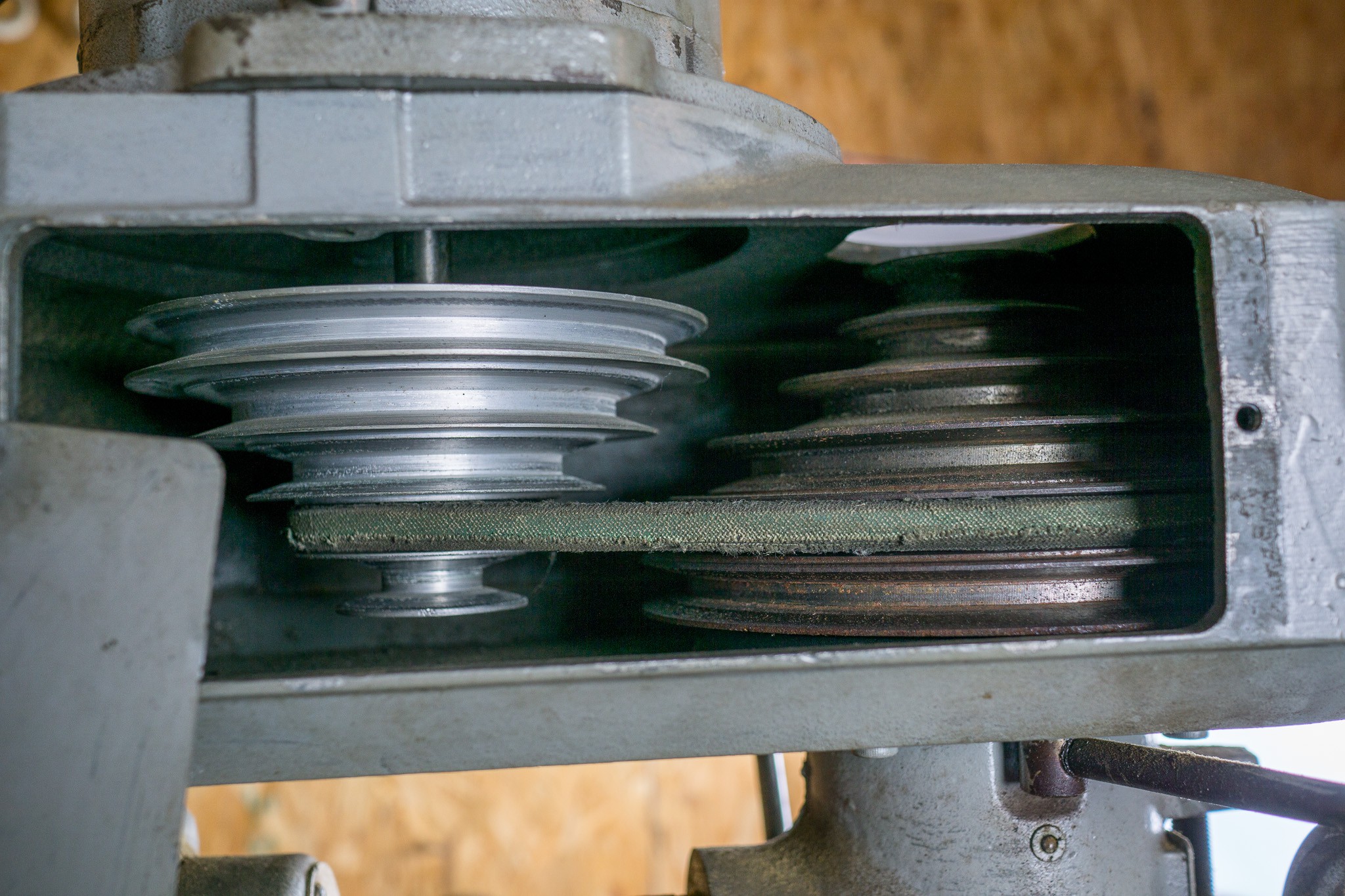
There is no gearbox for the vertical head, just a set of pulleys that you adjust to change the spindle speed. This gives a few rpm options: 370, 700, 1170, 2440, 4420 and 6300 RPM.
![]()
I plan on replacing the belt with a nice cog- or link-belt... the existing belt is pretty worn. The horizontal arbor is driven by an interesting mixture of pulleys and gears. There are 5 pulley speeds that you can select similar to the vertical head.
Then there is a "backdrive" mechanism that can be engaged. This is a set of gears configured similar to a lathe, which provides a 6:1 reduction. By engaging this, you can slow down all the pulley configurations. These slower speeds allow slab milling or other heavy cutting operations, or potentially lathing wide-but-short pieces.
The speeds available are: 60, 135, 240, 300 and 385 rpm with the backdrive engaged, and 375, 845, 1500, 1875 and 2400 rpm in direct-drive.
![]()
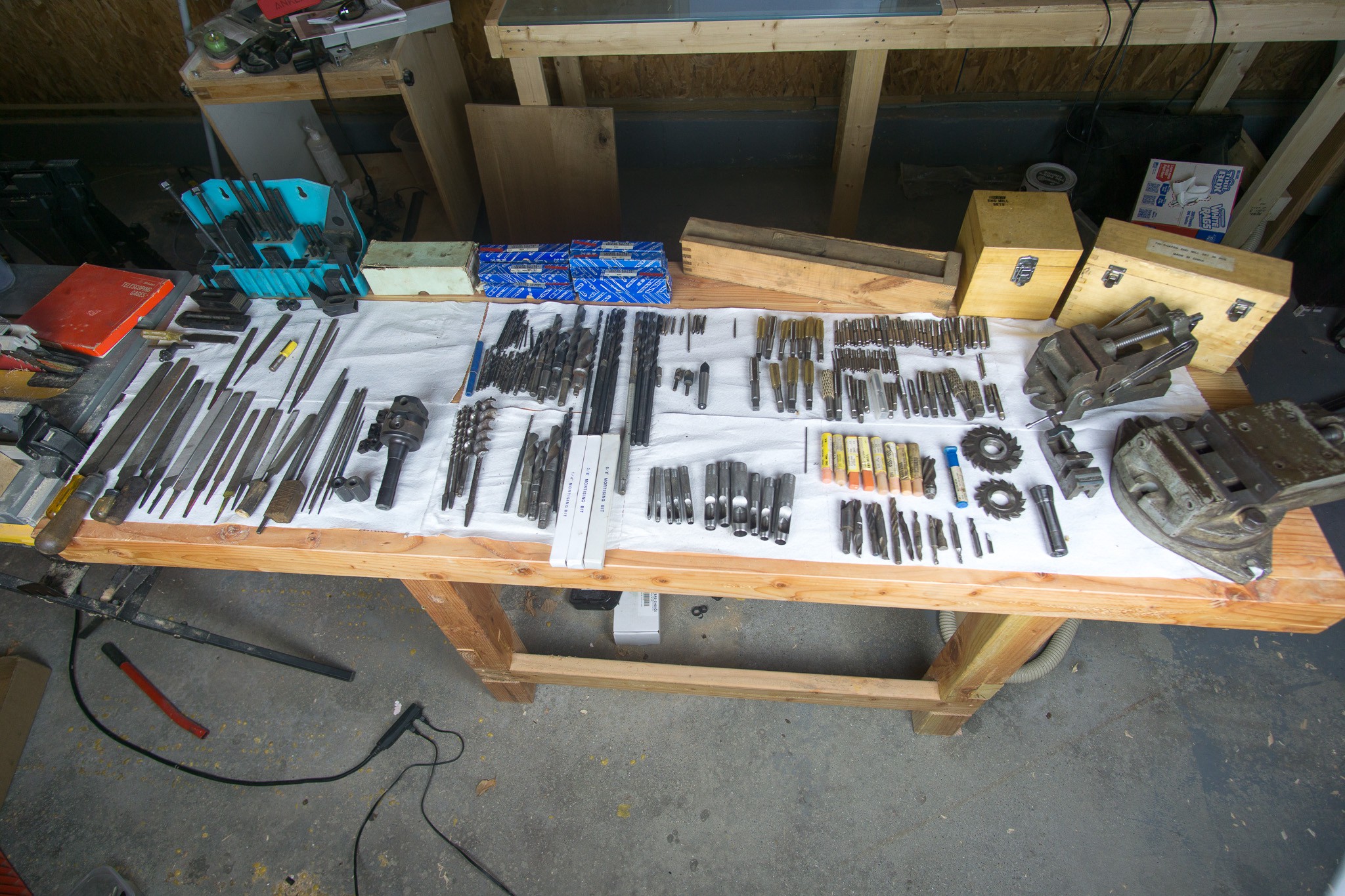
This mill was being sold as part of an estate sale, so I also nabbed a huge amount of tooling. Probably several thousand dollars worth of tooling, all told. Some of it is in rough(er) condition, but most of it is pretty good.
![]()
Most importantly, it came with all horizontal accessories (arbor, overarm support) and three vices (6.5", 3" tilting and a 1.5"). There is also the extra power feed as mentioned, as well as a rotary table and tilting tailstock. For the tooling, there's a wide array of end mills, taps, punches, drills files, clamps and a boring head. Oh, and some really nice mitutoyo small bore gauges.
I had to purchase a few essentials (R8 collets, parallels, some indicators) but overall the tooling that came with the mill should have me set for a while.
Over the next few posts I'll be pulling the head, spindle and quill apart, stripping what I can, cleaning grease, re-lubricating and repainting. Stay tuned!
Rockwell Milling Machine Rebuild
Rebuilding a Rockwell 21-122 Horizontal/Vertical Milling Machine
 polyfractal