Close
0%
0%

AWS/WeatherBug Display Resurrection

It's been orphaned, but I'm adopting it.

Similar projects worth following
AWS was a program to bring weather stations to classrooms, and their collective data to regional meteorologists. The old equipment turns up sometimes; I found a display and Master Control Unit (MCU) at a local school. This project pulls local weather data over WiFi, and sends it to the display without the MCU or sensors.

Background

That should explain what AWS was. And it's the most 90's thing you'll ever see, to boot!

According to Wikipedia:

In early 2011, AWS Convergence Technologies, Inc. (formerly Automated Weather Source) changed its name to Earth Networks, Inc. In November 2016 it was announced that xAd acquired WeatherBug from Earth Networks.

Their website (aws.com) is pretty great, too:

IT'S BETTER HERE...OUR CLOUDS ARE REAL! ...  You were probably looking for Amazon, but now that you are here, take a look at what we can do.

But, someone named [Brian] is still answering email at support@aws.com! Nobody responded from Earth Networks or WeatherBug. [Brian] said, 

We no longer sell or support these old digital displays, they were required to use with an actual weather station to display data.   If you wish to try and make it work without a weather station then you may try to do so, I'll give you the link to the user's manual for that display. http://download.aws.com/manuals/DisplayManual.pdf

That's better than a kick in the pants, I guess. The manual has a WeatherBug logo on it. Here's the meat of it:
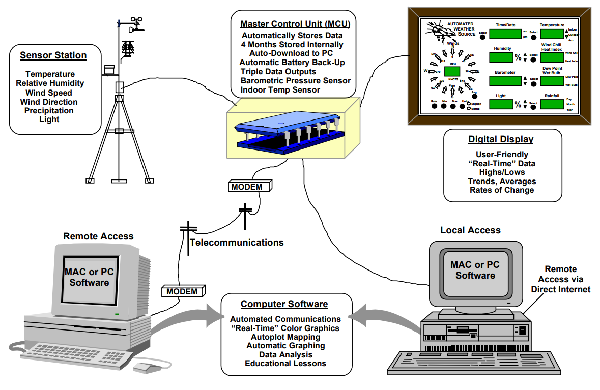
The MCU feeds the display, modem and a local computer. It is fed by data from a sensor station, which I don't have.
  • 1 × ESP8266
  • 2 × MAX487 Interface and IO ICs / RS-232, RS-422, RS-423 and RS-485
  • 2 × DS80C320 Microprocessors, Microcontrollers, DSPs / Microcontrollers (MCUs)

  • Humidity in Three Acts

    roleohibachi02/10/2018 at 02:22 1 comment

    [netmgr], who has similar hardware, realized why I was having trouble with the humidity field. It's not just one field, it's three separate fields that affect humidity! I believe they are two coefficients (I'll call them a and b), and a value. The dummy coefficients I had been sending had resulted in a nonlinear response to changes in value.

    Armed with that knowledge, I started adjusting the other values as well. Plugged in a=b=100, sent a range of inputs to the value field, and plotted a (linear, this time) regression in a spreadsheet. Result:

    Humidity is expressed as 500 * (161*percent + 1234) / 1983. 

    It may not seem like much, but it was the last "stumper"! 

  • Let's Get Physical

    roleohibachi02/08/2018 at 07:05 0 comments

    Armed with a working display library, I wrote a sketch for ESP. It's included in the examples directory of the library on GitHub. It builds on the work of [Daniel Eichhorn], who wrote a library for working with Wunderground's API. I modified his library slightly to parse some extra fields I needed, and to provide data in numeric datatypes. 

    The sketch pulls data that the display can use from the Wunderground conditions API, and sets the ESP's clock as well. The display's controller tracks the min and max values for us, like it or not. I'll have to write a function to compute and store some totals and averages in SPIFFS. Barometer rate is provided by the API, but only "rising/falling", not a value. 

    Unfortunately, the ESP8266 won't give up its internal temperature sensor info, so I have nothing to display in the internal or auxiliary temperature fields for now. Adding a temperature sensor would be nice, but I don't have one lying around. I do have an ESP32 or two, which has an internal temperature API. Future work, etc etc.

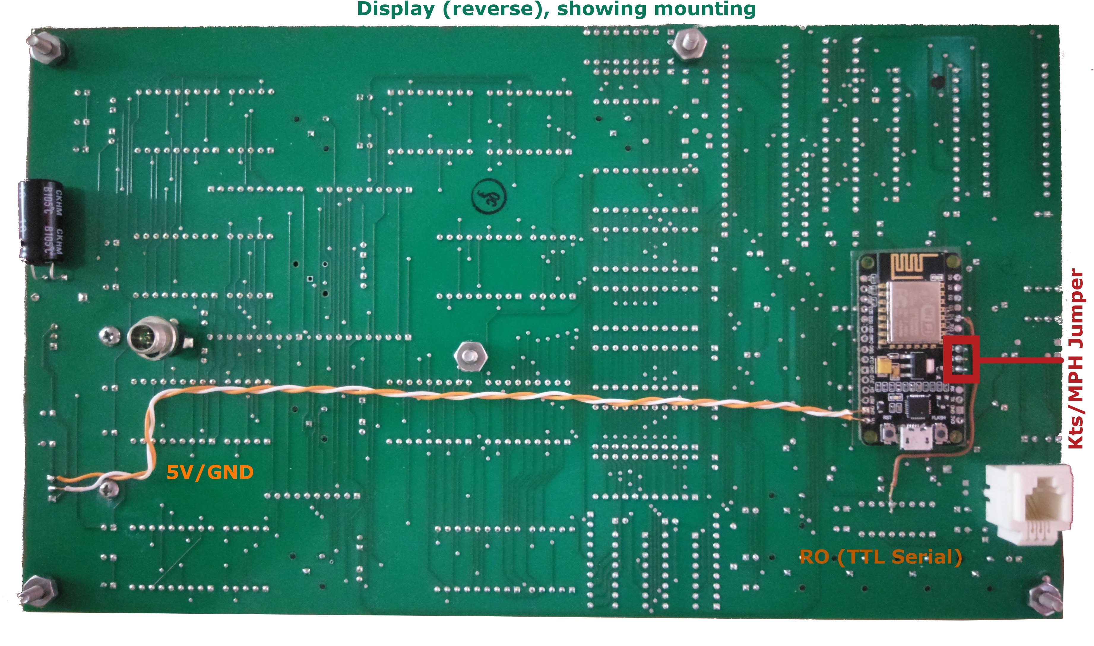
    Once this sketch was working, it was time to power the ESP from the display. The heatsinks on the voltage regulators weren't very warm, and my upstream power supply was large, so I decided to take the risk of connecting the ESP without doing much math or measurement first. Shadetree electrical engineers, I tell you. The average draw was no problem, but the spikes in current were making the display's controller reboot once in a while. I added some capacitors I scavenged from the MCU - there is some mild flickering, but no reboots. These are missing in the photo below (whoops).

    Physically mounting the ESP inside the case was elegant! There is a jumper/header with 3 pins to select between knots/mph for wind. By soldering NodeMCU D5 (mph), D6 (GND) and D7 (kts) to it, I not only anchor it in place, but also gain control of the knots/mph in software. A piece of plastic sheet is epoxied between the boards to prevent shorting. I'll drill a couple holes in the backplate later to expose the LEDs.

  • Arduino library

    roleohibachi01/19/2018 at 00:09 0 comments

    Good progress being made on a library, but it's not done yet. This was my first-ever library, and has actually been entertaining to design. Shout out to [netmgr], who's come forward with a 2007 version of this display, still addressable with the same protocol, who's helping test. If you have one of these displays, please message me! 

    - It works with any HardwareSerial or SoftwareSerial for hooking up the display - because it implements Printable. Just call SerialWhatever.print(mydisplayobject); to send the message with appropriate 0xAC line endings, etc.

    - it has setter functions for the various displays, with transfer functions for normal units. Some are still works in progress.

  • Decoder Ring

    roleohibachi01/15/2018 at 02:23 0 comments

    Great success with decoding the 9600bps serial data on the RO line. I've successfully identified the function of 17 of the 35 data fields. Many of them are probably just padding, too. Here's the breakdown, based on the message sent by the MCU and a small arduino sketch that modifies it. 

    • Messages begin with an LF (0x0A) and end with 0x8D.
    • 34 data fields, such as time, date, temperature, etc and padding fields are separated by 0xAC. They are not indexed, so must all be sent in order in each message.
    • Data are ASCII numbers, 0x30 - 0x39. Data contain a "don't care" bit, so sometimes are sent by the MCU as 0xB0 - 0xB9. No difference in functionality is observed. My code just uses ASCII.
    • Data may have multiple digits (variable word length); leading zeroes are ignored.
    • Some data fields, e.g. rainfall, are measured in hundredths, not base units. The decimal is inferred.
    • Range of displayable values is determined by how the processor handles the data. 
      • Rainfall, for instance, is maxed at 65535 hundredths of an inch, indicating it's written directly to a uint16_t.
      • Hours are transmitted in 24-hr format, but displayed in AM/PM format. If >12, subtract 12, set PM). As a result, 
    • Null bytes don't bother anything, so storing and sending strings/char*s are acceptable.

    Here is a little arduino sketch that showcases the data format, and sends it out using SoftwareSerial.

    #include <SoftwareSerial.h>
    SoftwareSerial softSerial(9, 10); // RX, TX. Connect TX to Display's RO.
    
    #define START "\x0A"
    #define EOM "\x8D"
    #define datalen 36
    char* data[datalen] = {
      START,
      "12\xAC",    //hours, 24-hr format. If >12, add 12. "111\xAC"=99.
      "34\xAC",    //Minutes, max 99. 
      "56\xAC",    //First field (US month)
      "78\xAC",    //Second field (US day)
      "01744\xAC",    //ind temp, 1744=0F
      "01744\xAC",    //outside temp
      "01744\xAC",    //aux temp
      "979\xAC",    //unk
      "4439\xAC",    //humidity
      "0\xAC",    //unk
      "07647\xAC",    //barometer
      "0\xAC",    //unk
      "65535\xAC",    //daily rainfall
      "00000\xAC",    //monthly rainfall
      "00000\xAC",    //yearly rainfall
      "000\xAC",    //Wind speed in km/hr. (display only has 2 digits, but truncates >99)
      "00\xAC",    //Wind direction. 15 LEDs, indexed clockwise. W=12. Wraps around. ESE lights two LEDs - I think it's a bug in the factory ROM!
      "0\xAC",    //unk
      "00\xAC",    //Avg wind speed
      "09\xAC",    //Avg wind direction
      "53\xAC",    //unk
      "0\xAC",    //unk
      "0\xAC",    //unk
      "65000\xAC",    //pressure rate, and associated rising/falling LEDs
      "0\xAC",    //unk
      "0\xAC",    //unk
      "0\xAC",    //unk
      "0\xAC",    //unk
      "0\xAC",    //unk
      "0\xAC",    //unk
      "0\xAC",    //unk
      "0\xAC",    //unk
      "0\xAC",    //unk
      "0\xAC",    //unk
      EOM
    };
    
    void setup() {
    
      pinMode(LED_BUILTIN, OUTPUT);
    
      Serial.begin(115200);
      while (!Serial) {
        ; // wait for serial port to connect. Needed for native USB port only
      }
    
      softSerial.begin(9600);
    
    }
    
    void loop() { // run over and over
    
    
      for (int i = 0; i < datalen; i++) {
        //Do not use serial debug messages in the same timing loop as the live data. It breaks timing.
        Serial.print(i, DEC);
        Serial.print(": ");
        Serial.println(data[i]);
        // 0xAC in extended ASCII is "¬". EOM looks like "�". Line feed will print an empty line.
      }
    
      digitalWrite(LED_BUILTIN, HIGH); //mimics MCU LED, but doesn't pulse RS485
      
      for (int i = 0; i < datalen; i++) {
        softSerial.print(data[i]);
      }
    
      digitalWrite(LED_BUILTIN, LOW);
    
      delay(100); //This can possibly be lower, but cannot be zero
    
    }

    I've also characterized a couple of the calculated fields, but not all of them. Here's what I've got, where 'x' is the serial value:

    • Temperatures (out, ind, aux)
      • x = 1000 * (25*F + 368) / 211
      • x = 1000 * (45*C + 1168) / 211
      • Range -15 - 260 F
    • Pressure
      • x = (11471 * (inhg - 28)) / 3
      • range is 28.00 - 31.44 inhg, which is sufficient for most of this planet.
    • TBD
      • Humidity
      • Pressure rate

  • No use crying: spilt milk with inverted serial

    roleohibachi01/08/2018 at 02:10 1 comment

    I borrowed a logic analyzer, and it did the trick. Here's what I learned:

    Paying close attention to the MAX-487 serial drivers, the "Driver Input (DI)" on the MCU and the "Receiver Output (RO)" on the display were inverted. Attempting to parse the inverted-serial data was no good - serial doesn't work like that. It also messed up my baud measurement.

    It was inverted because, I now know, phone cabling can be "reversed" (like a crossover or patch ethernet cable), or straight-through. Between patch panels, straight cables are normally used, but to the phone, the cable is usually reversed. Whichever one I've got on hand is the opposite of which the manufacturer intended. Furthermore, RS-485 signals are differential, so crossing the "A" and "B" signals perfectly inverted the receiver output. 

    I got halfway through making a crossover RJ-11 monstrosity when it occurred to me - I can test this by jumpering the boards together. I connected MCU-A to Disp-A, and MCU-B to Disp-B with a short wire. Now the displayed data makes a lot more sense! The MCU has (incredibly) kept accurate time and date using just a coin cell for, what, 20 years?

    The non-inverted signal was 9600bps - simple. I didn't even have to measure it, as the logic analyzer software's auto-baud blurted it out. I removed the serial driver from the display board, copied a data burst into an arduino sketch and replayed it where the RO line would be, and it worked perfectly.

    Now, on to parsing and fuzzing the data!

  • My Kingdom for a Logic Analyzer

    roleohibachi12/11/2017 at 02:12 0 comments

    With no sensors connected, I put some RJ11 between the boards and powered them on. To my surprise, "NO SIG NAL" disappeared, and was slowly replaced with what appears to be random data. Or, maybe, the MCU is interpreting the null voltages from its sensors as max or min values. Who knows! I'm just glad to see something flowing, because it gives me something to sniff. I was worried that I'd have to spoof a PS/2 "Sensor Net", whatever that is!

    I don't own a proper logic analyzer. However, I do own an arduino! So I dropped in the excellent work of [Andrew Gillham], a SUMP-compatible logic analyzer for arduino.

    The results show that the "dim LED" isn't dim, but instead, directly connected to the transmission line! It's dim because it's transmitting serial data on and off. I wonder about the effects of the diode on the transmission line...

    I see also that it's sending 100msec of data every 1sec. The narrowest gap I measure appears to be 79usec, which would correspond to something like 

    Putting a serial monitor on the line spits out data, but it's not necessarily good data. As soon as I figure out how to use SUMP/OLS to decode serial data, I'll know more. I'd like to record the stream and try to replicate it, then change parts of it to determine what is written to which 7-segment.

  • Any Port in a Storm

    roleohibachi12/11/2017 at 01:58 0 comments

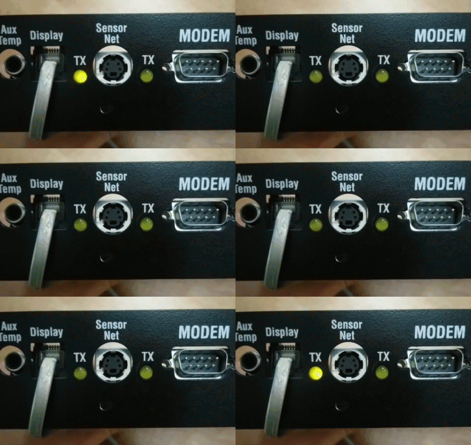
    The MCU has lots of ports:

    • Unknown barrel jack, "Aux Temp"
    • RJ11, 6-Position 4-Conductor (6P4C), "Display"
    • PS/2, "Sensor Net"
    • DB9, "Modem"
    • DB9, "Computer"
    • Barrel jack, "Power"

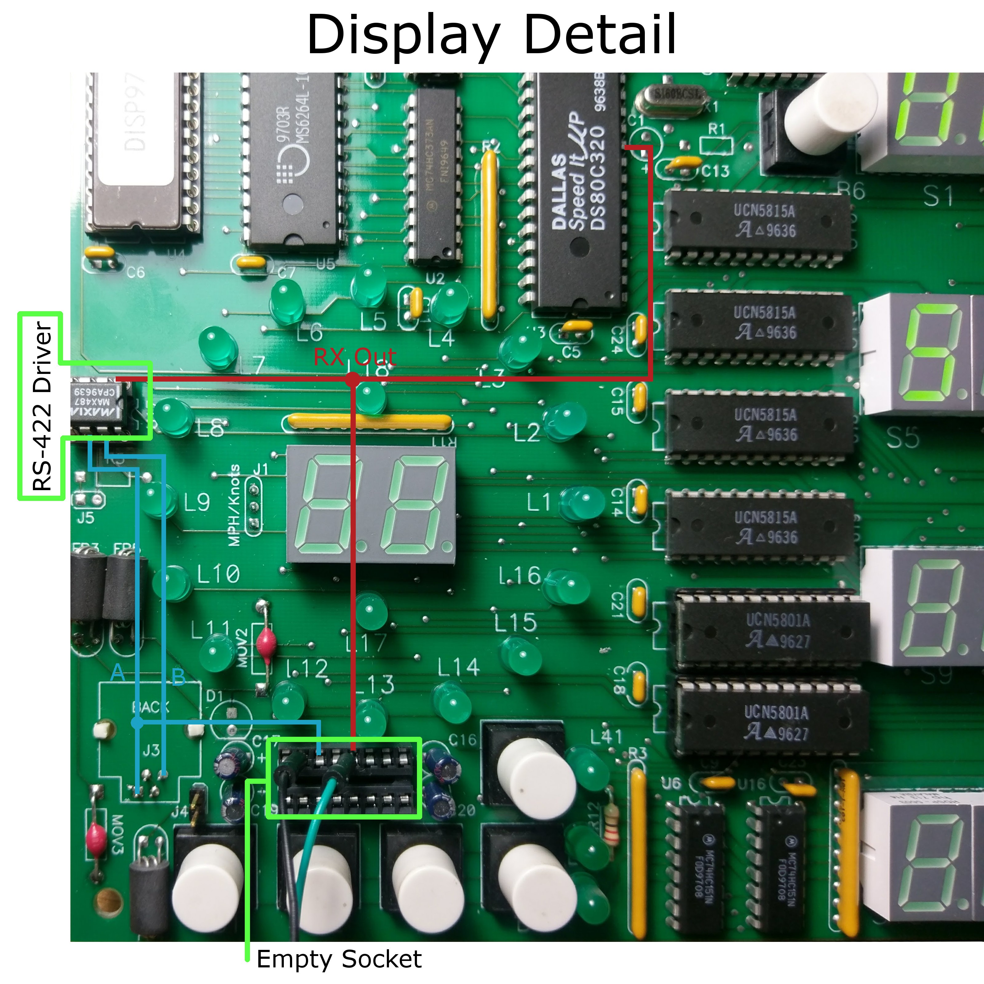
    The display board just has a matching RJ11 port, but with only the outer two wires connected - "6P2C".  The center two are unconnected, but can be connected through a varistor to ground with a jumper. Maybe an upgraded version of this board speaks RS-232 over these wires? I don't claim to know.

    Behind each RJ11 port is a pair of ferrite beads...

    Side note. I learned that a ferrite bead, like a grounded capacitor, filters out high-frequency noise from a circuit. But it does so by, essentially, acting like an antenna. It increases inductance, and thereby impedance. A capacitor, on the other hand, will lower the impedance, so isn't as good for communication lines.

    ... And behind the ferrite beads, a MAX487 chip. The MAX487 has something to teach me about serial communication. PC Serial, known as RS-232, is referenced to ground. But RS-422 and RS-485 (an old Macintosh standard) use differential voltage. You've got an "A" and a "B" output, and if A>B by 200mV, it's a "1". If A<B by 200mV, it's a "0". So it's also got some built-in hysteresis. Sounds pretty great to me! Unfortunately, a bit of a pain. 

    Poking around with the multimeter some more, I find that all the important pins except "B" on the Display board's serial driver are connected to an unpopulated chip socket! Perhaps the hypothetical "upgrade" board spoke RS-232 instead, allowing the chips to be swapped. I put a probe on the "Receiver Output" (RO), which should nicely decode the RS-422 signal for me.

    Later, it may be trivially easy to remove the MAX487 entirely, and spoof the RO line with the ESP8266.

  • Finding a Way In

    roleohibachi12/11/2017 at 01:41 0 comments

    That's "so dim", not "SO-DIMM". This board predates such things!

    I see a Dallas "Speed it μP" DS80C320, which is a 80C32 (like an 8051 with no ROM) - one on each board. I also see a removable PROM on each board, with a paper label leftover from manufacture. Could be the paper is covering up the UV port - this is old enough that EPROMs weren't taken for granted! I'll cover it up with some extra tape to be sure I don't erase anything with sunlight. If worse comes to worse, I'll have to dump these.

    But before we jump into ROM dumps and reverse engineering, it might make more sense to attack this from another route. Replacing the microcontroller is always an option, since the LED drivers are all discrete chips. I'll keep that one in my back pocket as well.

    For now, I'm interested in making the same noise as the MCU as it performs legitimate communication.

  • Power On

    roleohibachi12/11/2017 at 01:29 0 comments

    I didn't receive these devices with power supplies, so the first step was determining their requirements.

    Opening the wood and metal cases was accomplished with screwdrivers. The manufacture dates marked on the boards are circa 1997. 20 years - not a bad run, I suppose.

    The voltage regulators on the boards are 78MxxCT, which take any Vin under 35V. Pretty much any laptop power supply with the same polarity in the barrel jack works nicely - mine are from a pair of Fujitsu.

    Power on to the boards! The display lights up brightly, and shows "NO SIG NAL". Charming. The MCU is rather dim, but blinks a light once every second on the reverse next to an RJ11 jack, and has a steady green light on the front. 

View all 9 project logs

Enjoy this project?

Share

Discussions

Dominic wrote 05/31/2024 at 04:13 point

Do you know if the data going to the display is the same information that would be coming from the weather sensors? I'm working on a similar project that uses the MasterControl to take in information for non-OEM sensors.

  Are you sure? yes | no

Michael Cullen wrote 01/16/2018 at 20:26 point

RS-422/485 is not just an old mac thing - its use of differential signaling makes it good for long runs - very long runs - on twisted pair. It’s still used a lot in industrial applications- I came across a lot of it when I worked on broadcast automation systems.

  Are you sure? yes | no

roleohibachi wrote 01/19/2018 at 00:24 point

Cool! I've had problems with long runs of TTL before. Since I'm wiring directly to the RO line, I've got a couple spare driver ICs and the knowledge to use them!

[netmgr] and I were ruminating: if you tied "B" to ground and sent 5V serial data on 'A', wouldn't it be technically valid RS485? The MAX487 driver only requires a 200mV difference between A and B. This method would be usable without a separate driver IC, albeit over shorter distances.

  Are you sure? yes | no

netmgr wrote 01/14/2018 at 21:22 point

my display looks to be much newer, dated 2007.  Uses surface mount chips, but still uses the max487 and has the empty dip socket

  Are you sure? yes | no

Does this project spark your interest?

Become a member to follow this project and never miss any updates