Todd
Todd-
Sound... off :(
12/28/2017 at 19:56 • 0 commentsInspired by Piezo Christmas Songs I wrote code to play music on it, but I goofed and ended debugged it on an Uno (for serial debugging info). But then I ran out of program space porting it back to the ATtiny85. Not sure I'll be able to scavenge the ~200B I need....
-
A next-step idea comes up under-voltage
12/21/2017 at 20:00 • 0 commentsA bunch of ideas have been running through my head on next steps but many involve a 3.3V processor, which is sometimes TTL compatible with 5V, but sadly, according the MAX7219 data sheet:
Logic High Input Voltage VIH 3.5V
Bummer.Sure, I can make little step-up circuits for each of three data lines, or get a quad level converted module, but either just means more wiring, complexity and expense.
While there's a 3.3V "equivalent" of the MAX7219 (the MAX6951), there's no pre-made or semi-made LED matrix modules available with it. And after skimming the DS on it I'm not convinced it'll even run an 8x8 LED matrix.
-
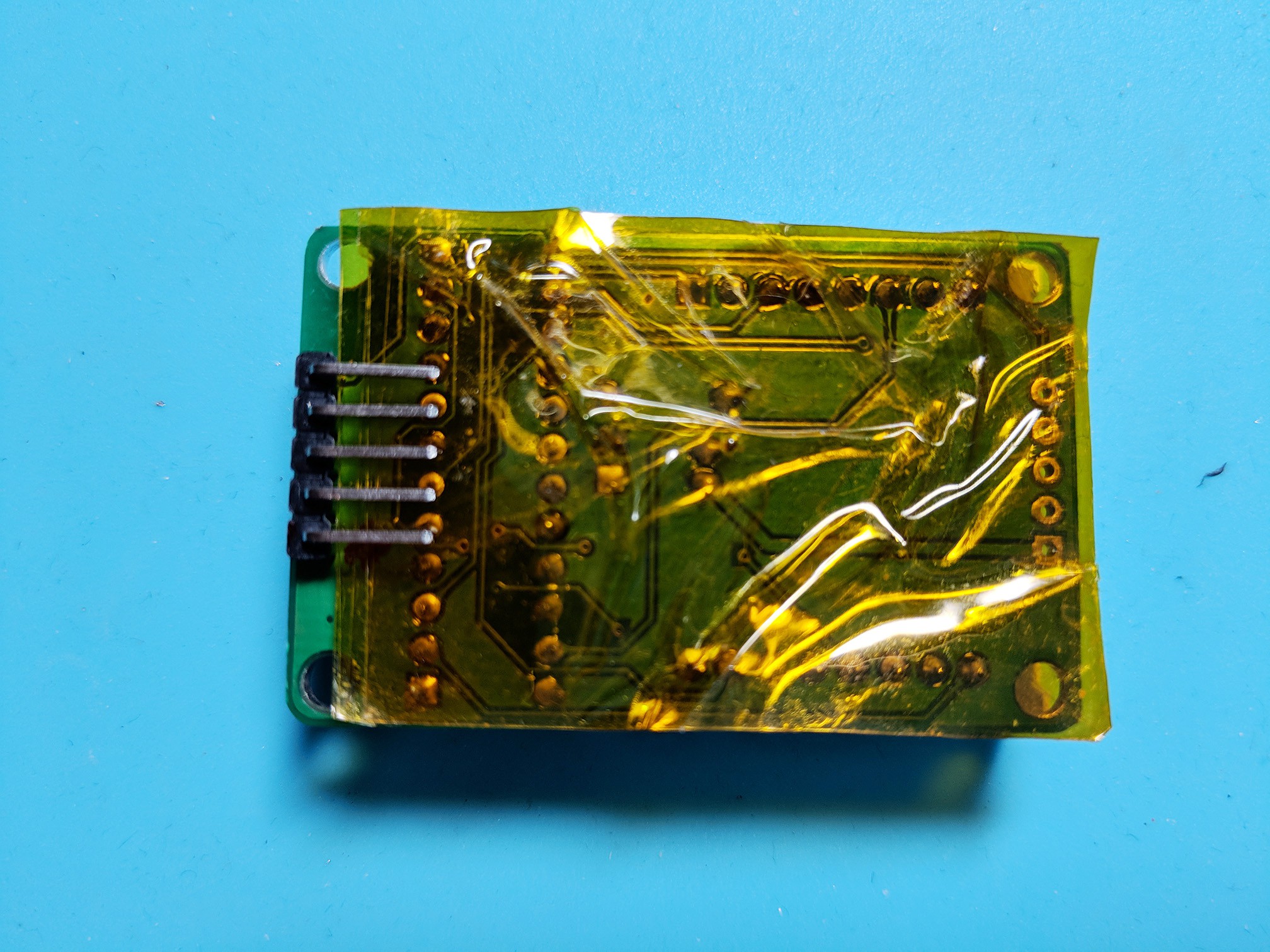
If it's good enough for the Apollo Lunar Module, it's good enough for this
12/20/2017 at 04:22 • 0 commentsTo protect from shorts between the LED matrix module and my custom board, I applied 3 or 4 layers of Kapton tape to the back of the module. Some of the ends of the through-hole leads were pointy enough to break through a layer, thus the multiple layers.
![]()
-
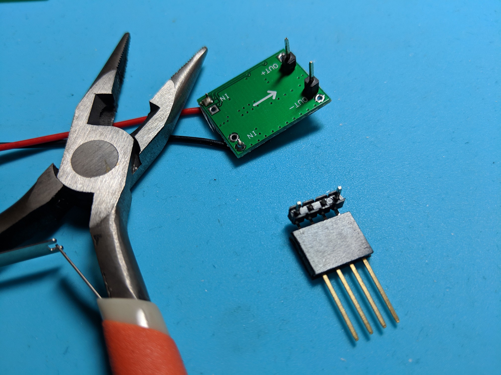
The DC-DC Buck Converter
12/19/2017 at 09:12 • 0 commentsA purchased module. I just had to put the headers on. This one is adjustable so it's important actually to adjust it using the little pot. ;)
Originally I'd put two single headers, but then when I decided to use the 90degree ones, I further decided to use 4 headers connected for added strength, which means trimming down the pins that have no corresponding holes on the module.
![]()
In retrospect if I had mounted the female header further to the left and reversed it's direction, and then soldered the DC-DC board's headers "backwards" under it, it would have fit better on the board without an overhang. Next time.
The 9V battery clip's leads are thin and fragile and I've already broken one at the solder joint. Some type of adhesive or strain relief would be good.
![]()
-
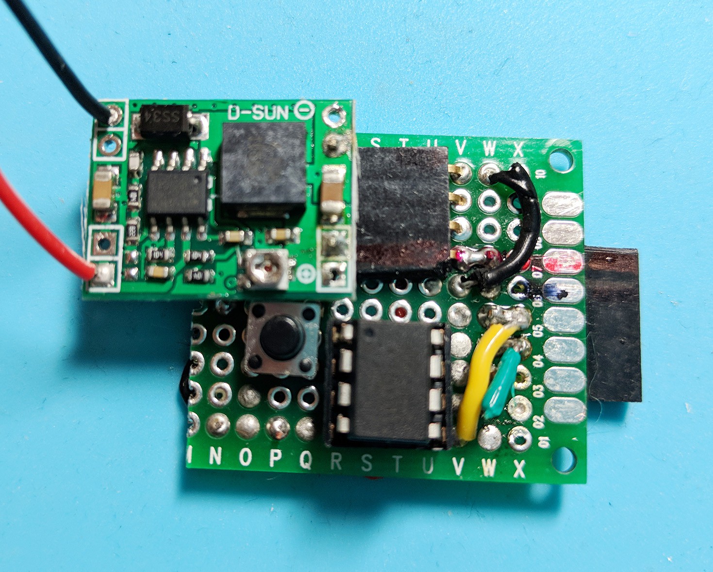
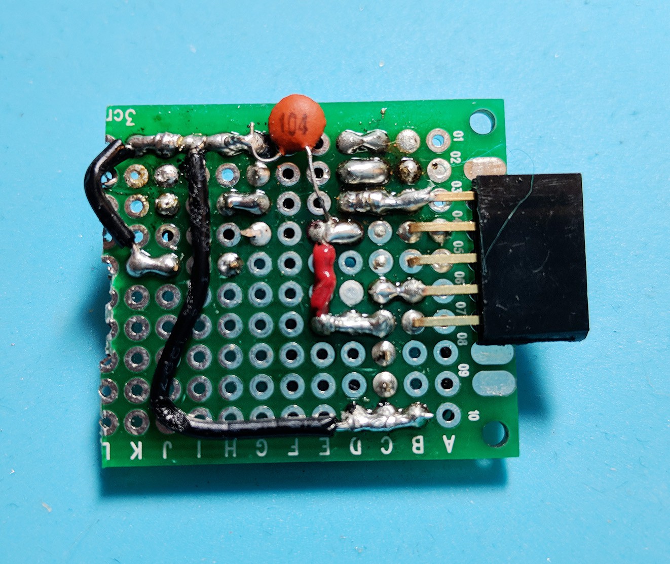
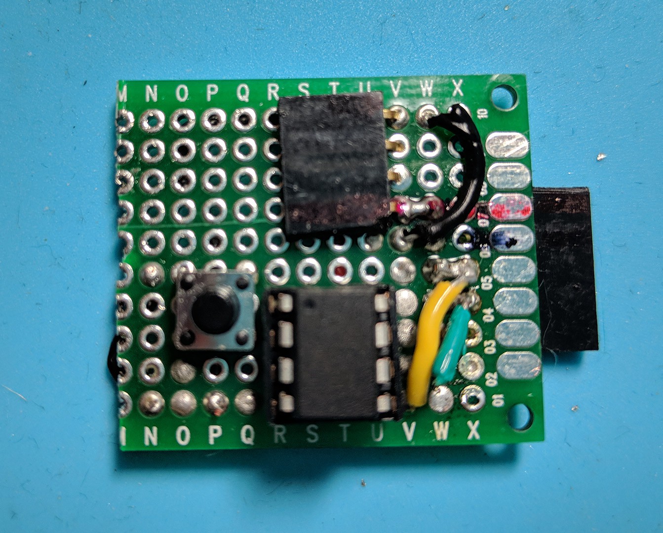
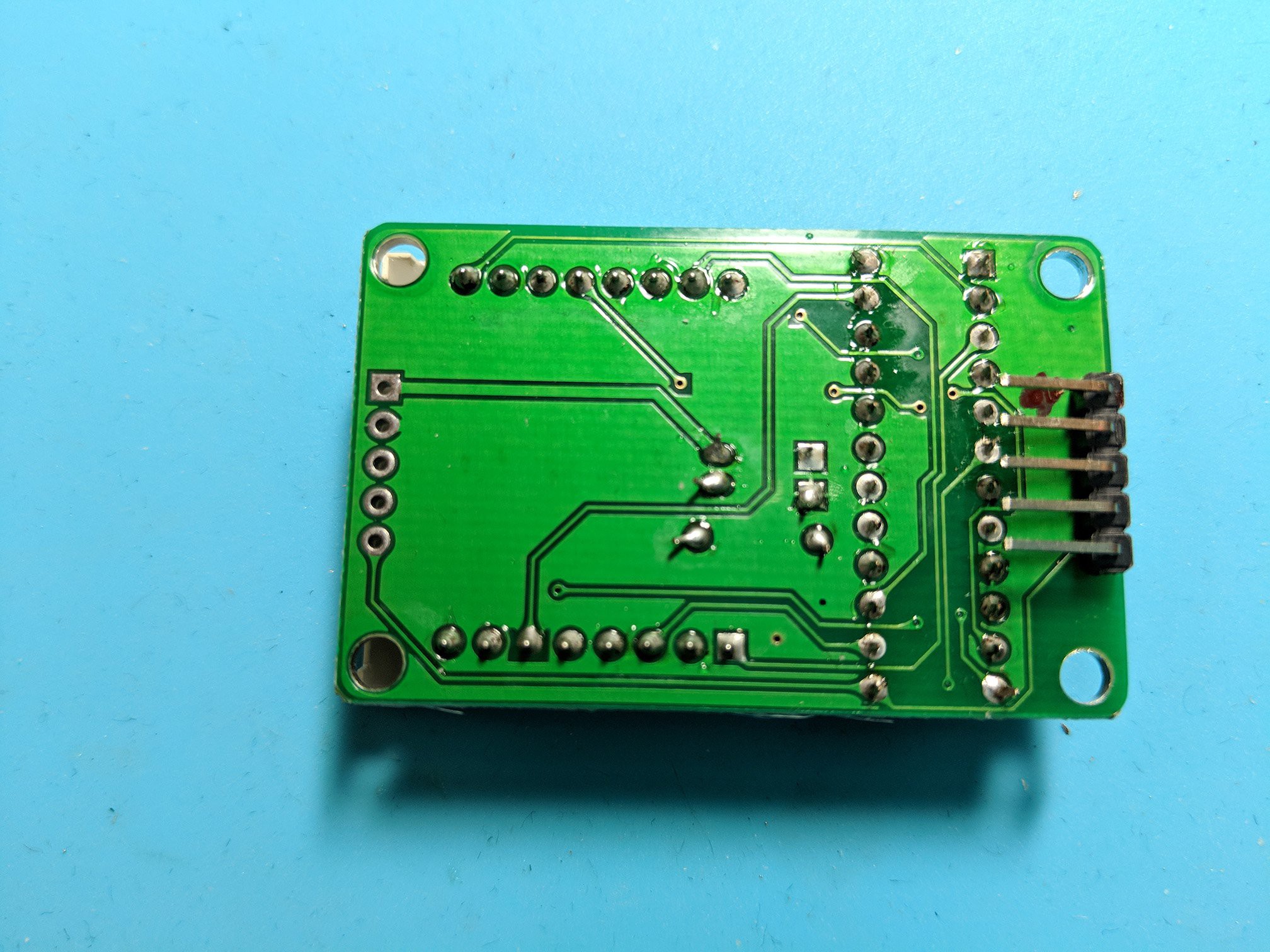
The Custom Board
12/19/2017 at 08:59 • 0 commentsI cut a 70mm x 30mm PTH breadboard in half. Bent the long-leaded headers to 90degrees. The second header is for the DC-DC buck converter.
I didn't really have a plan on how to wire this I just kept referring to the breadboard and putting parts in different locations and orientations until it just "fit" best. I marked VCC with red and GND with black just to make sure I didn't release any magic smoke. As I mentioned before I again tried to connect the button incorrectly, thus the second (shorter) ground wire. When will I learn?
It was a PITA soldering this... it would be nice to DIY a custom PCB.
![]()
![]()
-
The MAX7219 LED matrix kit assembled
12/19/2017 at 08:34 • 0 commentsThere's a couple components under the LED matrix. It's a pretty easy assembly. Check the "description" for a link on finding pin 1. New versions of the kit use the MAX7219EWG which is a 24pin Wide SO, and the whole board is hidden behind the LED matrix, making it easier to orient them in different directions or even a grid (they also use SMD components so you're only soldering headers).
I soldered the header pins backwards and "inwards" so I could hide the other board behind it.
![]()
![]()
-
No serial, so add an LED
12/19/2017 at 08:18 • 0 commentsNo debugger, no serial (well, when using nearly all the pins, and most of the Program Storage), you have to go by your gut. Or, add an LED and set it to light at certain checkpoints/conditions.
![]()
I also added a decoupling cap.
-
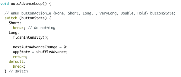
What? That compiled?!
12/18/2017 at 21:47 • 4 commentsHmm, when you copy and paste an enum into a `switch` so you don't get the names wrong but then you forget to add some keyword back... can you find it? ;)
![]()
Surprisingly, this compiles (but doesn't work as expected)... and I'm not a C expert enough to know why. But wow, that stumped me for a couple hours!
-
Add Button
12/18/2017 at 19:52 • 0 commentsAdding a multi-purpose button started with needing a "pull" so the button input pin didn't float. I decided to use the internal Pull-up capability of the tiny (so the button is wired to GND).
Next came debounce, see Arduino example code but I tweaked a bit. Originally I combined the debounce and the button control logic, but when things got a bit more complex it got messy, plus I was violating the Single Responsibility Principle. So I moved the button code to it's own extensible state machine function. I tend to use SM's everywhere in MCU's (when I'm not being lazy).
Now I was able to cycle through different designs with the push of the button, and eventually added "long press" and even "very long press" to control it further.
I don't know about you but I always wire buttons wrong the first time - I want to go "straight through", but notice how the correct wiring uses pins on a diagonal.
![]()
-
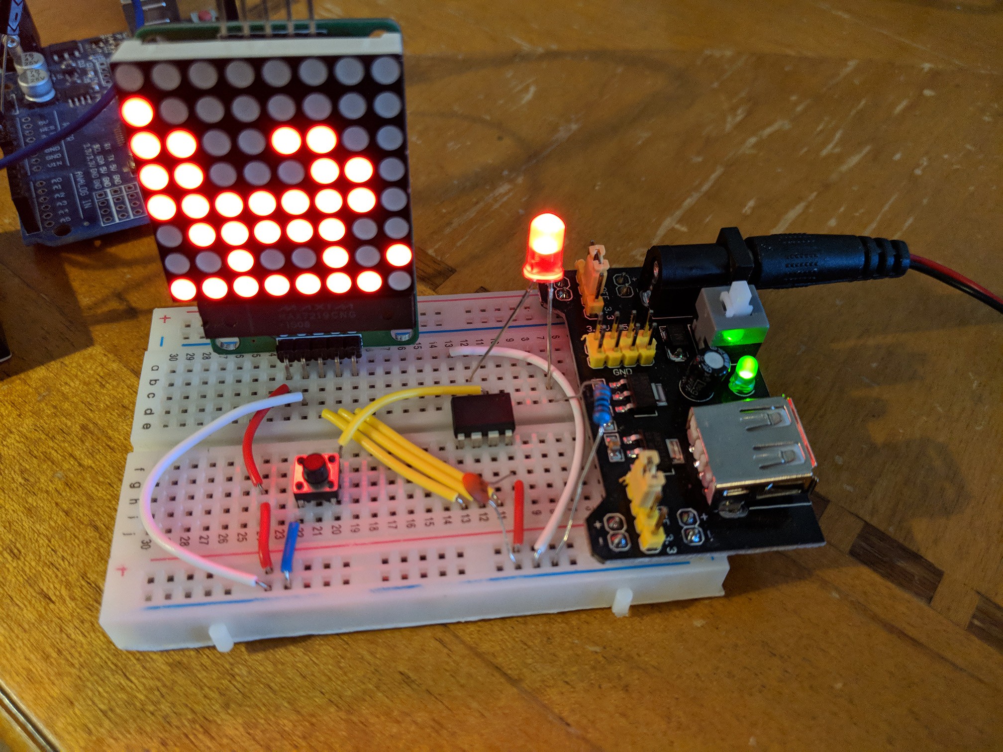
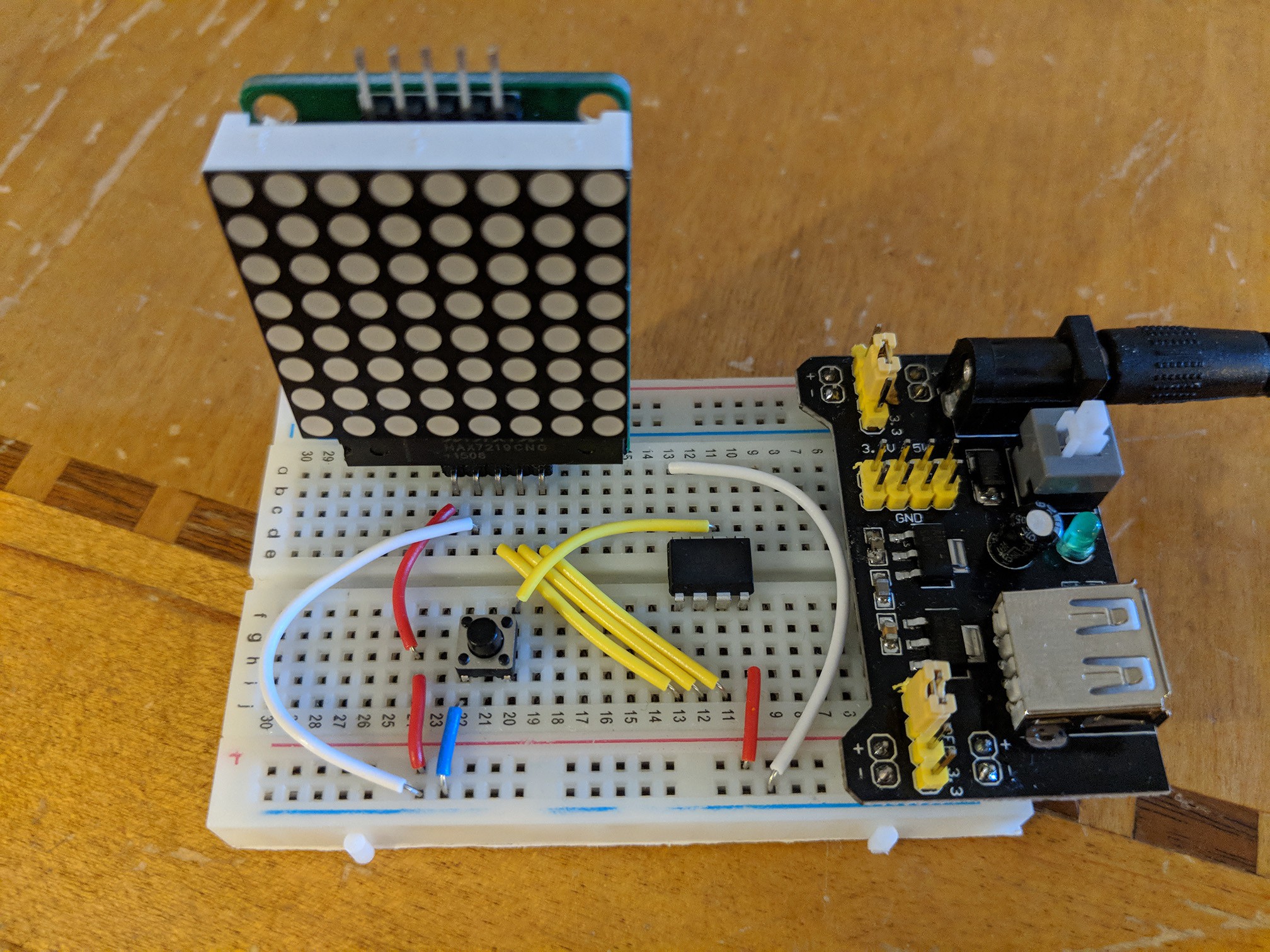
First attempt
12/18/2017 at 17:56 • 0 commentsJust a breadboard, no button, and a slightly modified copy of the MaxMatrix demo, and I was up and running.
I have a ton of ATtiny85's so I always like to work them into projects. Behind the white breadboard you can see the smaller black one which is connected to an Uno (as ISP) for flashing. The extra step of having to move the chip for burning is a bit annoying but the tiny is just so compact and convenient.
![]()
Holiday 8-bit ^2 LED Ornament
An 8x8 LED matrix animated ornament powered by an ATtiny85