 SimpleTronic
Quick Tour Video:
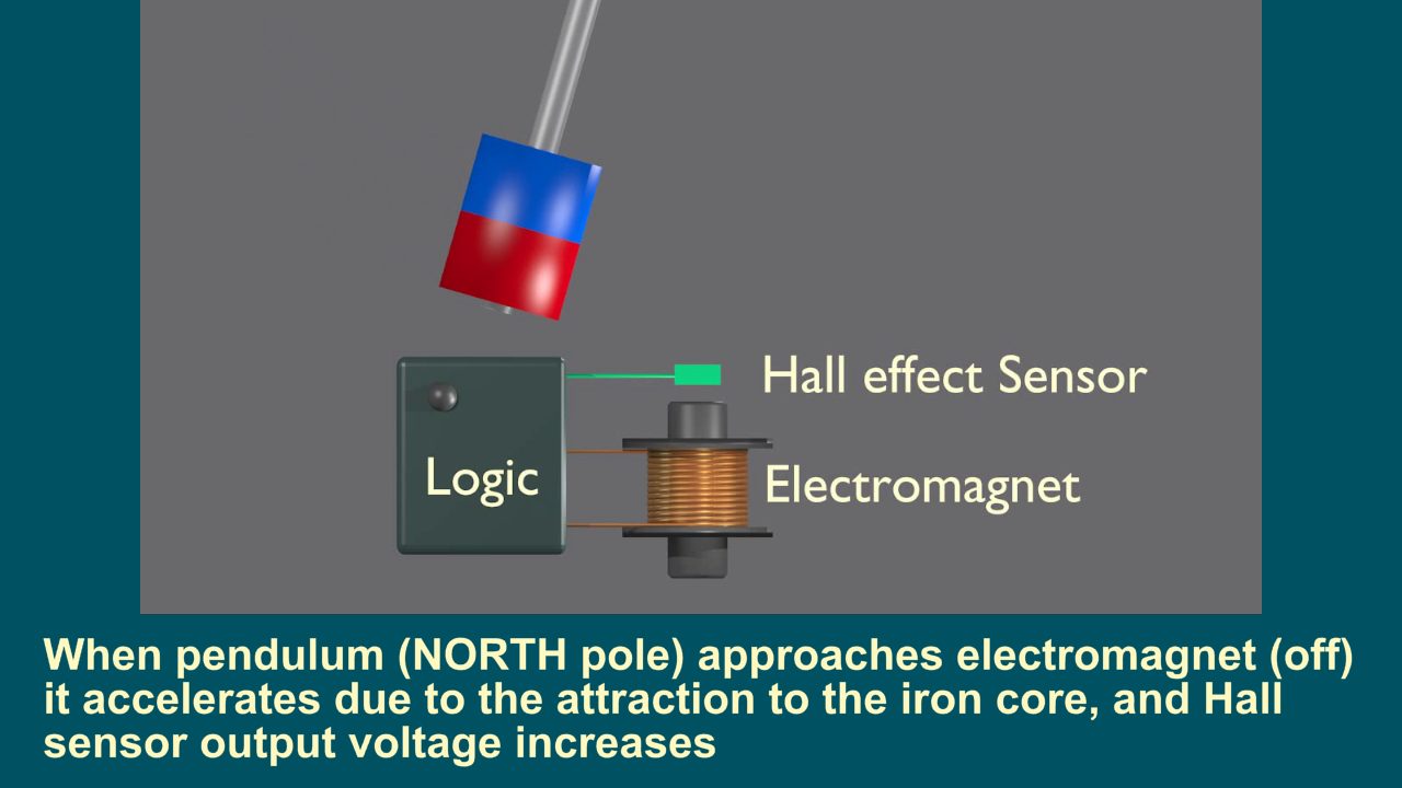
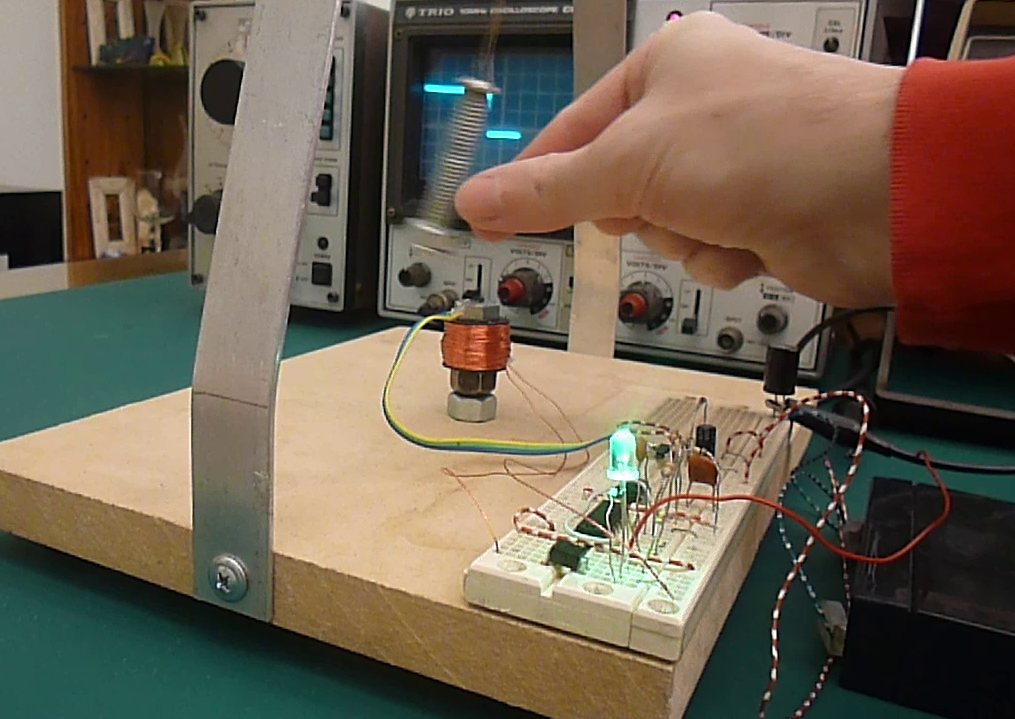
Operation phase 1:
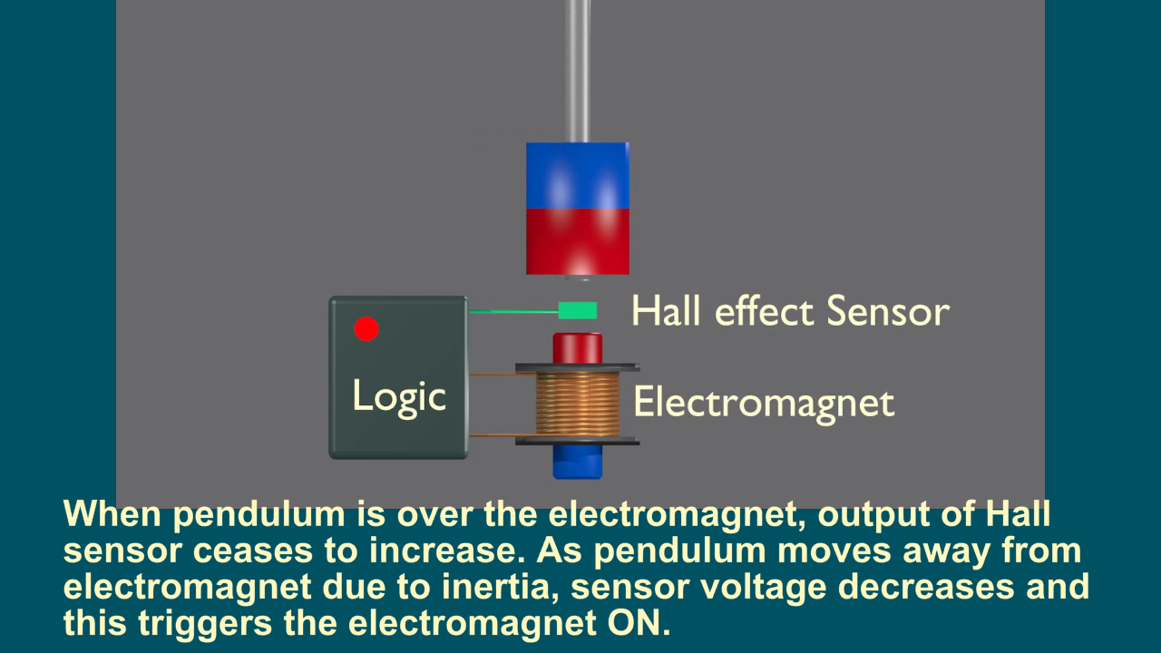
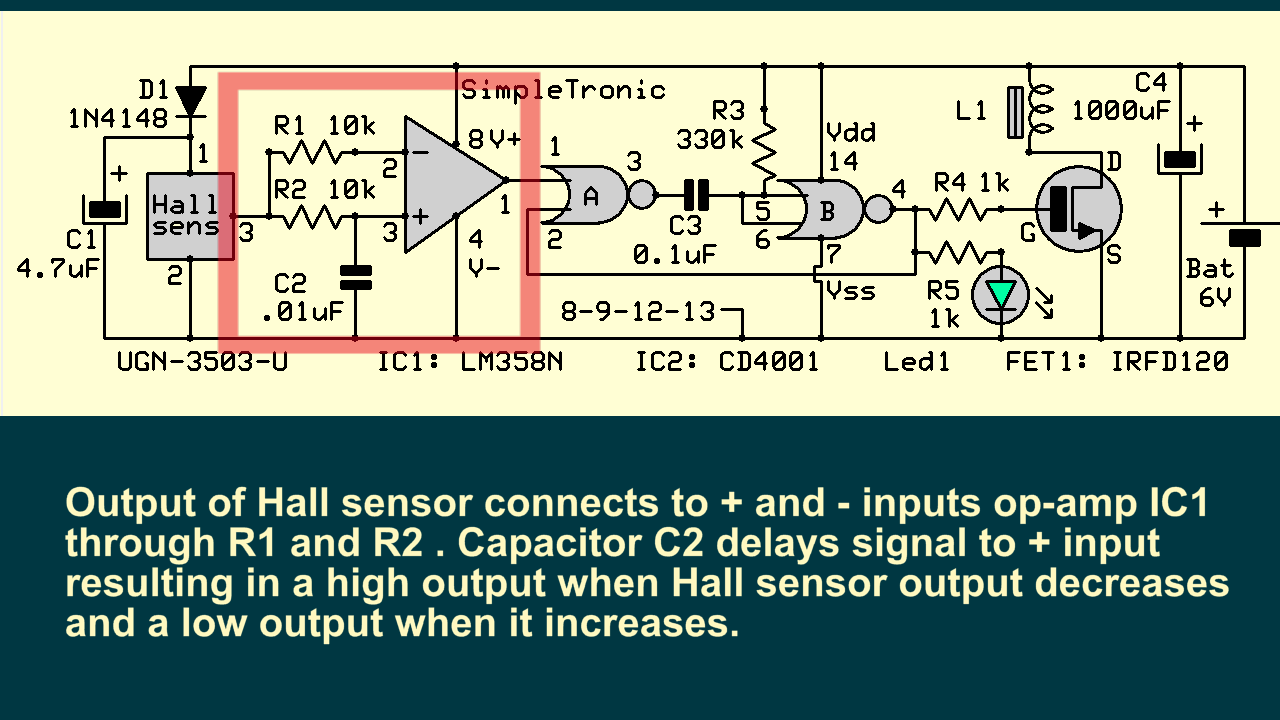
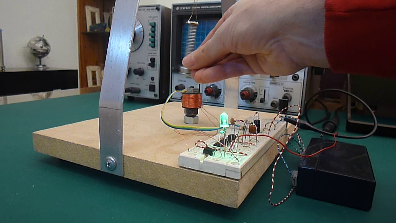
Operation phase 2:
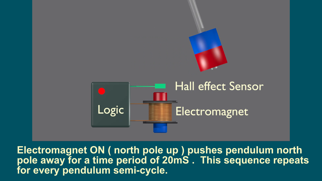
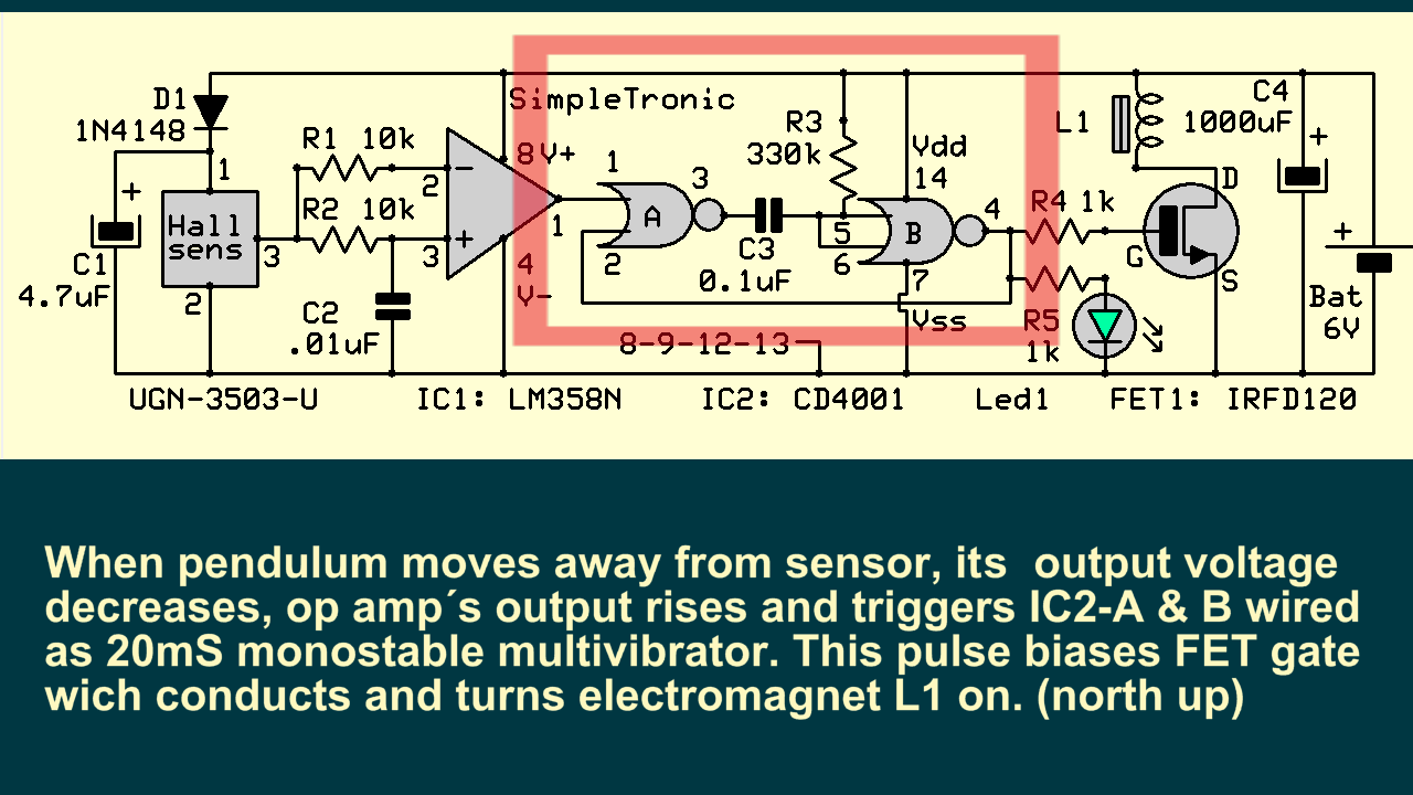
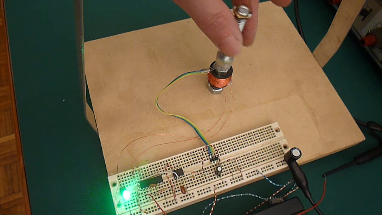
Operation phase 3:
Circuit Diagram:
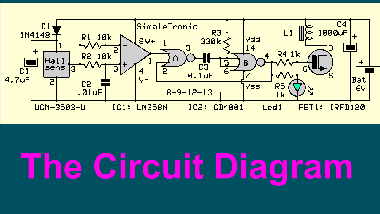
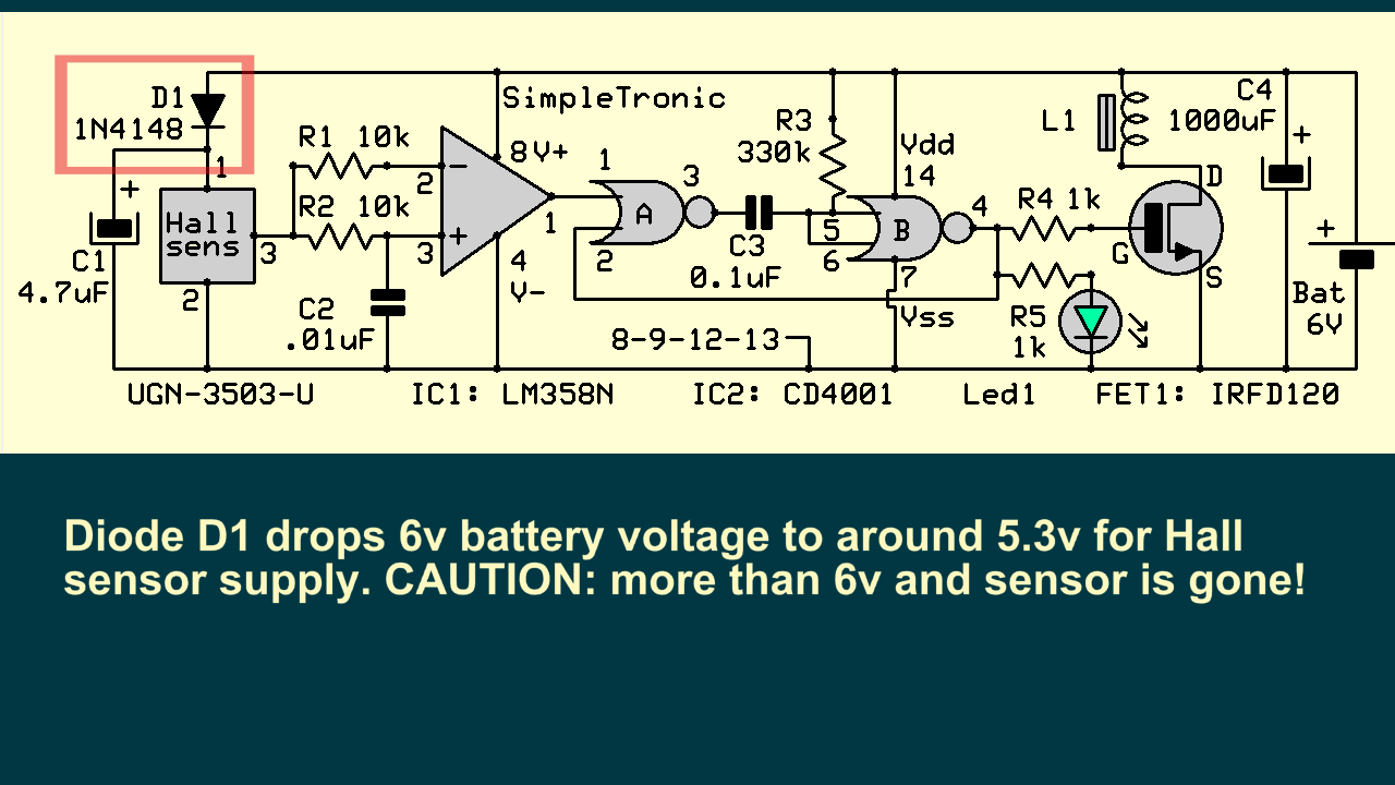
Circuit operation details:
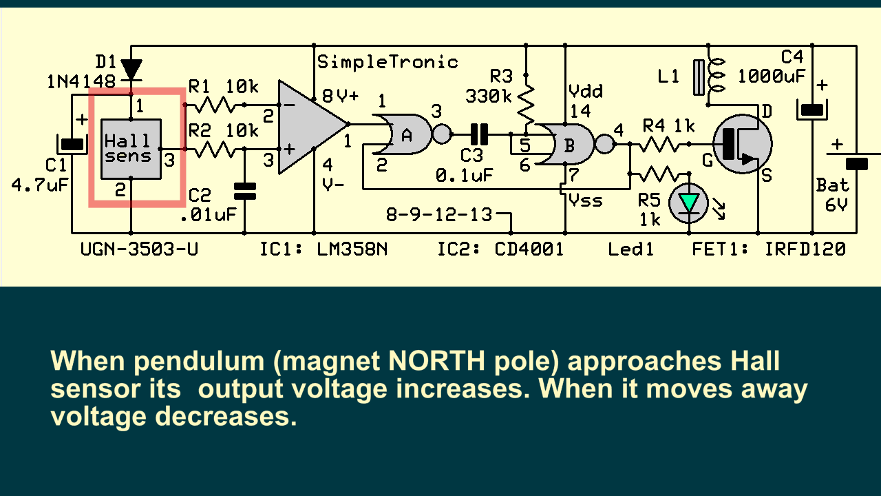

Magnet / Electromagnet / Hall sensor:

IMPORTANT:
1) electromagnet north pole pointing UP
2) pendulum north pole pointing DOWN
3) hall sensor branded side UP
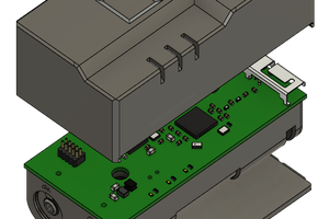
Main Components:
Hall sensor: UGN-3503-U
IC1: LM358N ( dual OP amp )
IC2: CD4001B (quad cmos nor gate )
FET1: IRFD-120( n-channel power mosfet )
Video:
Images:


 Edward
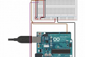
 hIOTron
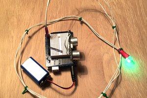
 Rasmus Ljungmann Pedersen
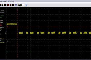
Hi! I built this circuit according to your circuit diagram. The halls sensor detects the magnet and generates a pulse which is present in Pin 1 of the CD4001. But there is no pulse coming out from pin 3 of the CD4001 and so the rest of the circuit beyond this point is not working. I already double checked all the physical points of the circuit board to be sure it was not a mechanical failure. Then I also tested your circuit diagram in a simulator and came up with the same non-functioning result. I cant understand why the project is not working here but it does work in your video. Can you offer me some advice please?