 Grant Giesbrecht
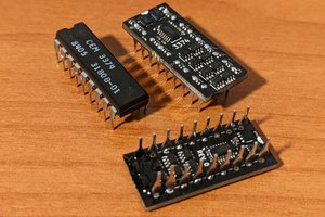
I used a cheap CNC machine to mill the PCB used for this radio. All the components I ordered from Mouser. The boost converter uses an ATTiny microcontroller to act as an oscillator which can be configured to provide different voltages from the boost converter if necessary. I have it set to provide about the maximum voltage, but by adjusting the duty cycle of the output wave you can get different voltages. I didn't have a dedicated SMPS chip available, hence the improvised MCU solution.
0%
0%
AM Radio Transmitter #5
A terrible transmitter made just for kicks
Become a Hackaday.io member
Already have an account? Log in.
Just one more thing
To make the experience fit your profile, pick a username and tell us what interests you.
Pick an awesome username
hackaday.io/
Your profile's URL: hackaday.io/username. Max 25 alphanumeric characters.
Pick a few interests
Projects that share your interests
People that share your interests

 Arnov Sharma
 hesam.moshiri
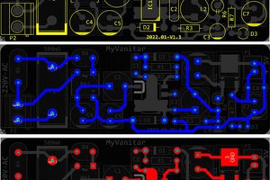
Sorry. I don't think that a low performance comes from the antenna. A long wire as actually a quite good antenna if it is tuned to the right length and if you do correct impedance matching.
But as an RF engineer I notice several bad/strange things:
1.) No double sided PCB. Use a double sided PCB and let one side be a complete ground plane. This gives you a solid ground and stable impedances
2.) Are this serpentine traces a substitute for a proper coil? With "AM" you probably mean the medium wave range, like 500kHz to 1600kHz. PCB traces as coils or resonators can function in the 100s of MHz range but give very poor performance at these low frequencies.
3.) Not any tunable LC circuit - very strange in a radio circuit, especially in a transmitter. It is absolutely necessary to tune the impedance matching of the antenna to the output stage. Otherwise you will not get a good efficiency and range.
I also do not see any power transistor which could justify a 30V supply :-)
But if you really want a step up converter, why don't you use a chip designed for this instead of a microcontroller? With an internal regulation amplifier and proper phase/frequency response o f the control loop. Then you could adjust the voltage with single potentiometer and do not have to reprogram the thing. For your fixed duty cycle even e 555 timer would be enough.