Calebe94
-
LCD Set up
12/27/2017 at 14:08 • 0 commentsOKAY, now that we have the raspberry set up, we can star the assemble of parts.
Let's make the LCD work!
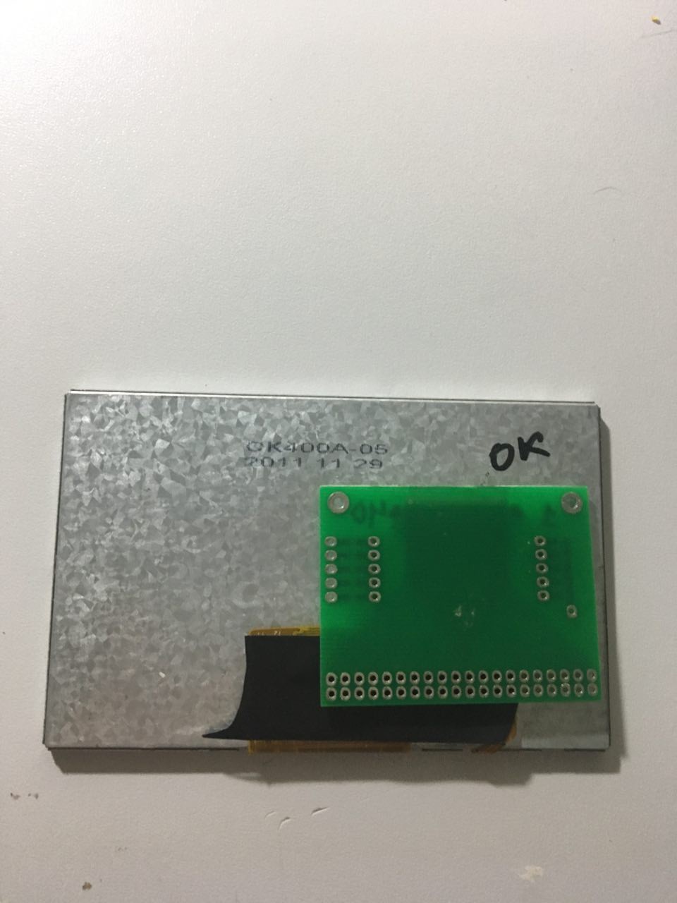
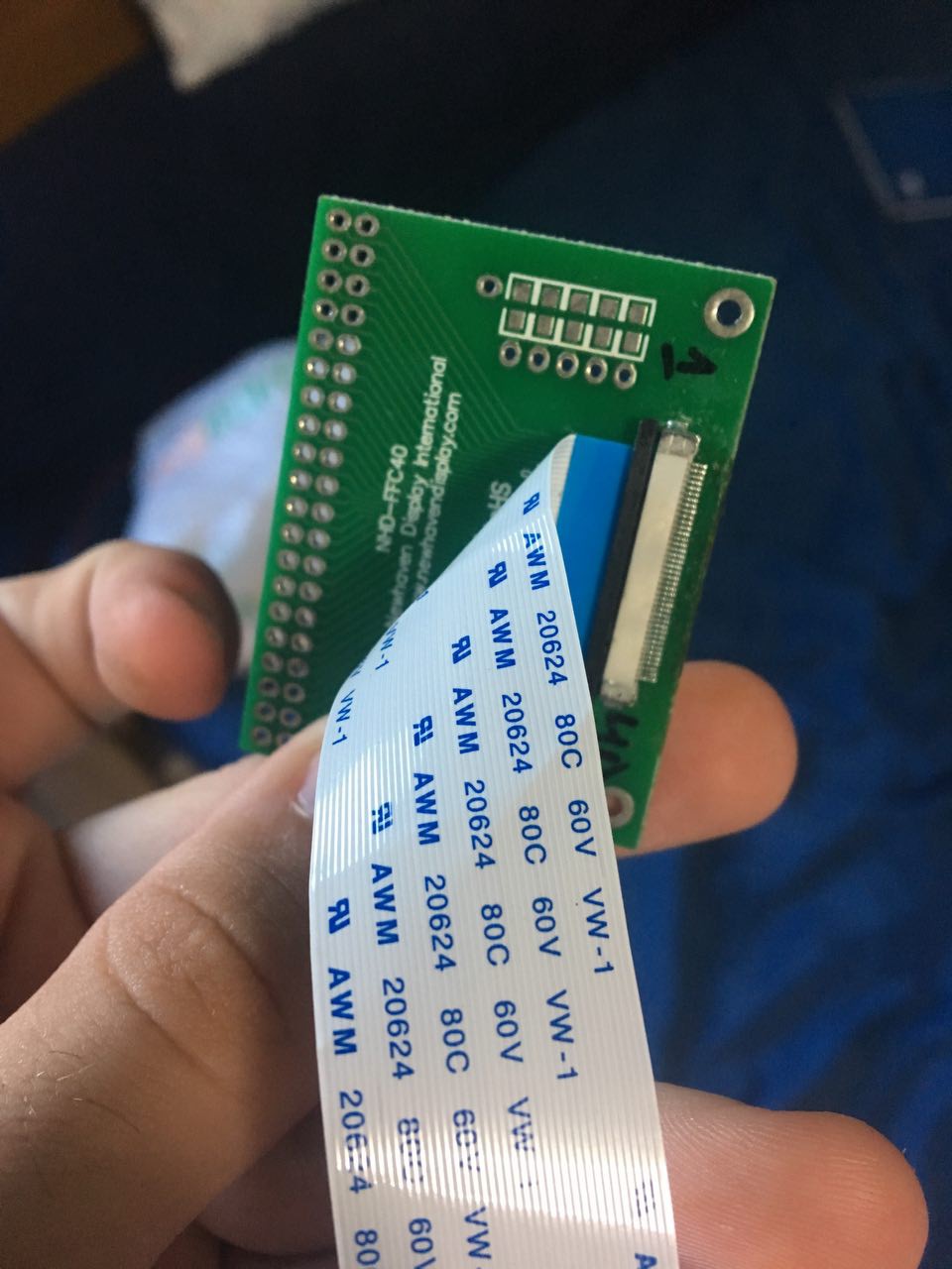
First thing that we need is a adapt board ( its on components list), so we can solder every pin on 40 pin connector to the 40 pin GPIO on raspberry.
![]()
![]()
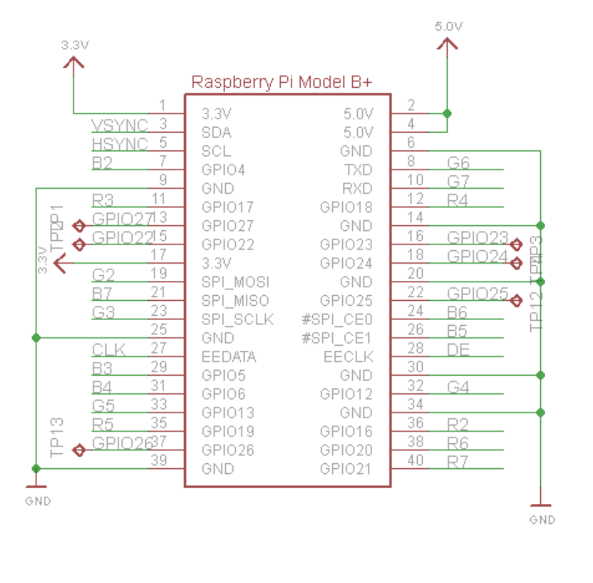
Now we can start solder the pins, the schematic is this:
![]()
![]()
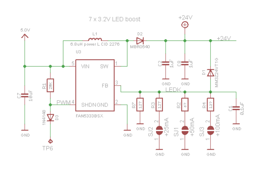
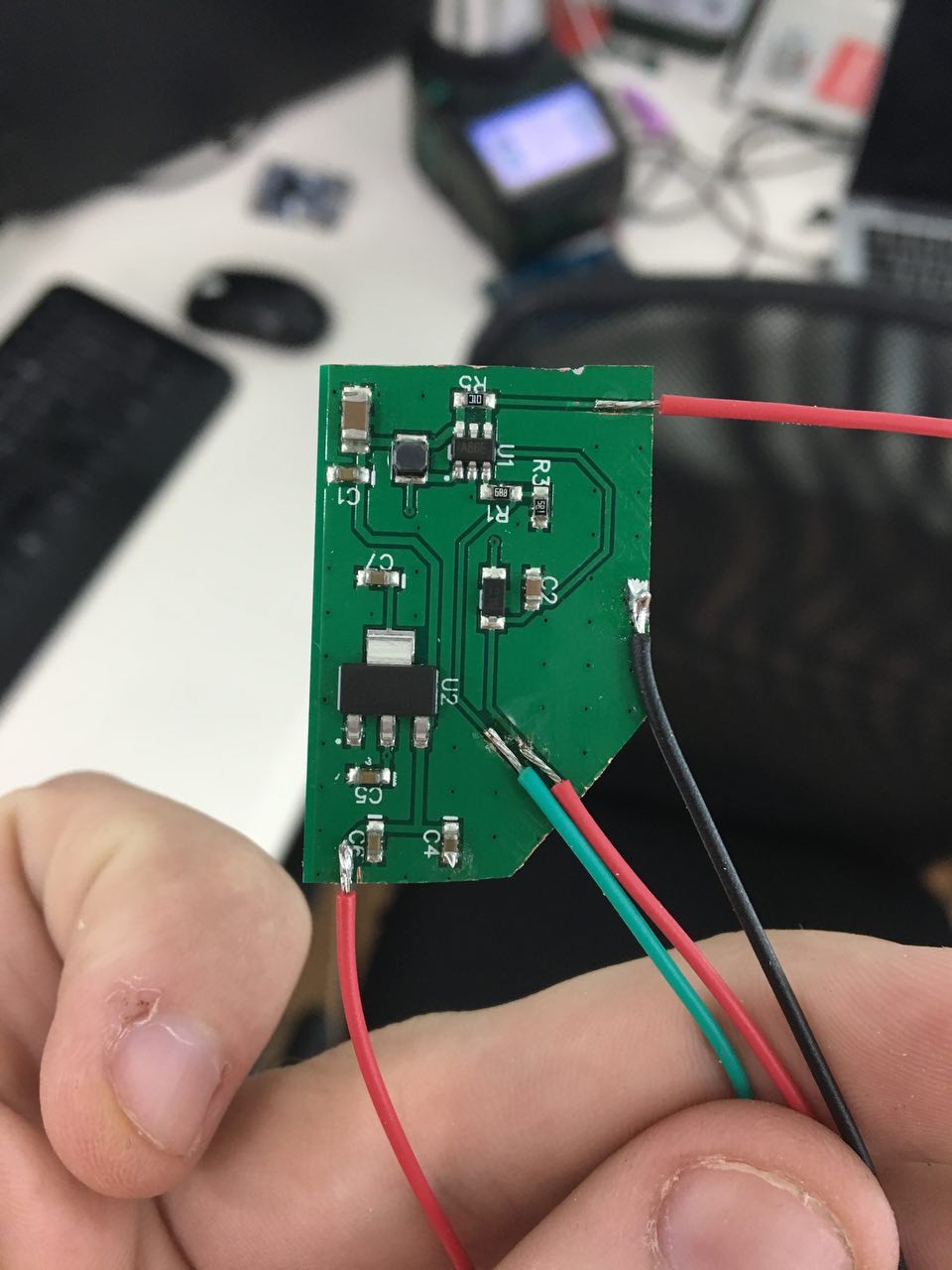
The hard part is the backlight circuit, because its not a simple step up, you can use this circuit:
![]()
I have a different circuit here, and i prefer to use it.
![]()
Now you just need to enable this lcd in raspberry.
First you need to download this DPI file and paste on boot partition of SD card.
and edit config.txt also in boot partition, you need to put this:
# Disable spi and i2c, we need these pins.
dtparam=spi=off
dtparam=i2c_arm=off

# Set screen size and any overscan required
overscan_left=0
overscan_right=0
overscan_top=0
overscan_bottom=0
framebuffer_width=480
framebuffer_height=272

# enable the DPI display
enable_dpi_lcd=1
display_default_lcd=1

# set up the size to 480x272
dpi_group=2
dpi_mode=87

# set up the hsync/vsync/clock polarity and format
dpi_output_format=520197

# set up the size to 480x272
hdmi_timings=480 0 40 48 88 272 0 13 3 32 0 0 0 60 0 32000000 3
Now just reboot.
And that's it.
-
Removing what we don't need
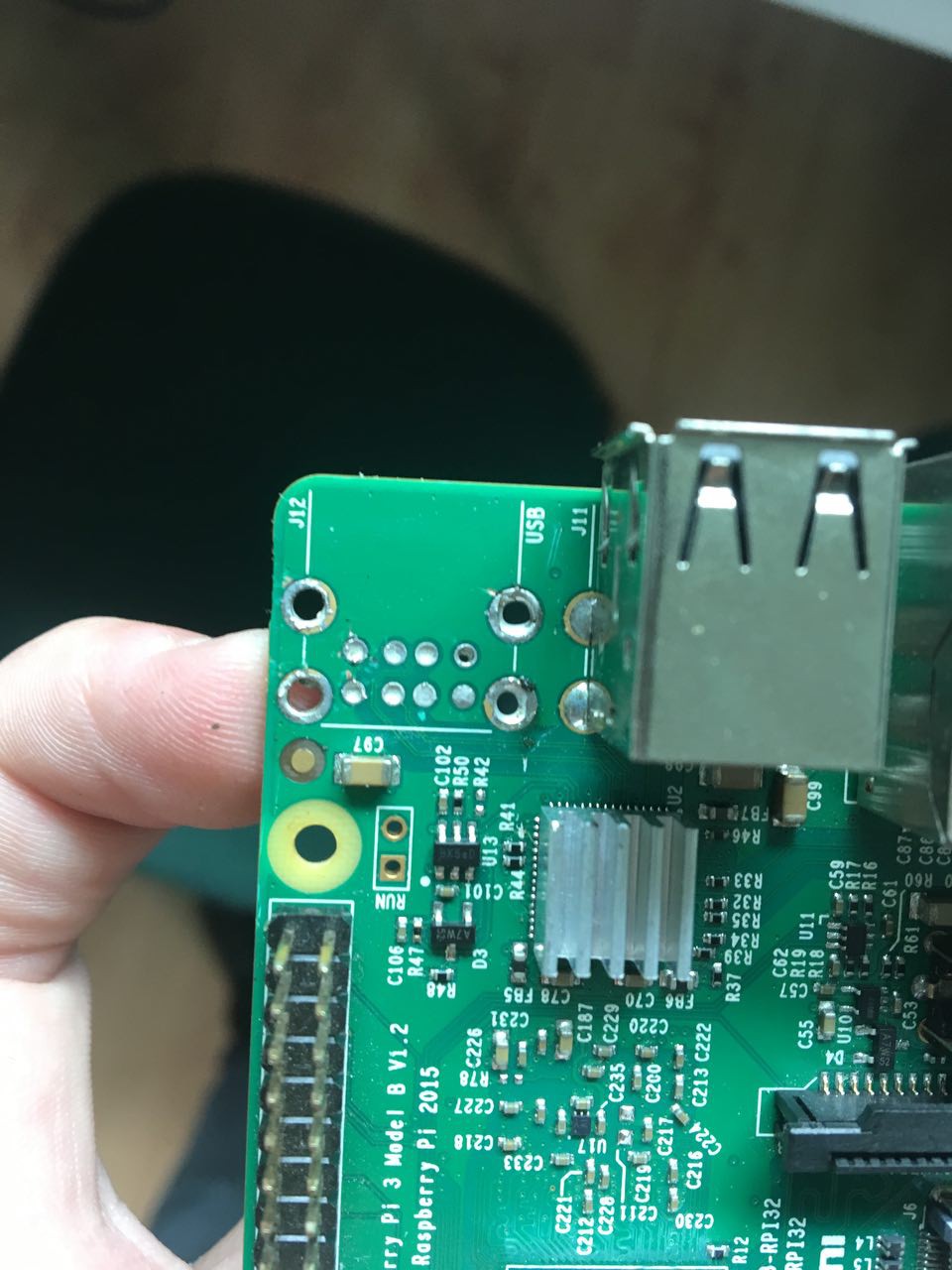
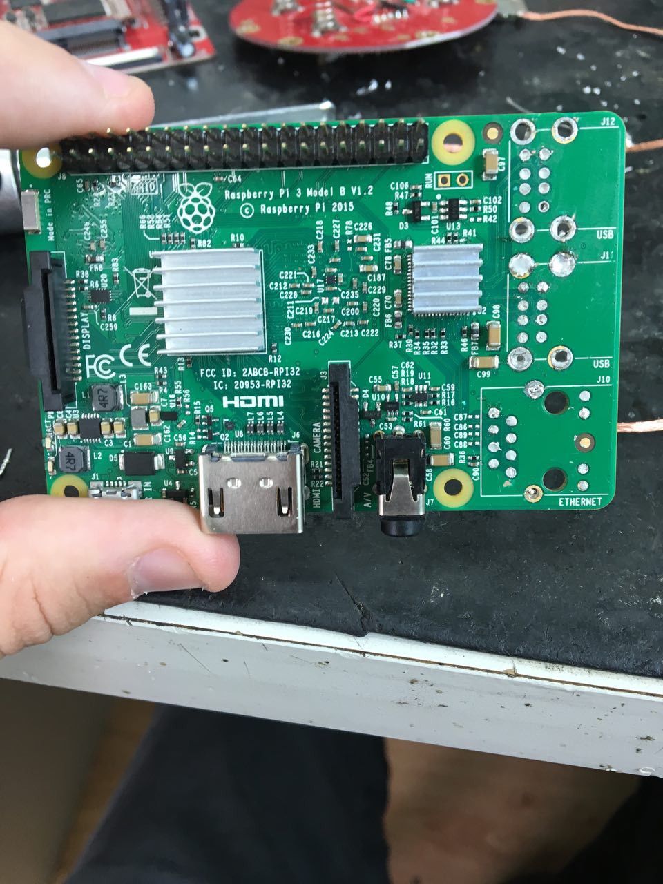
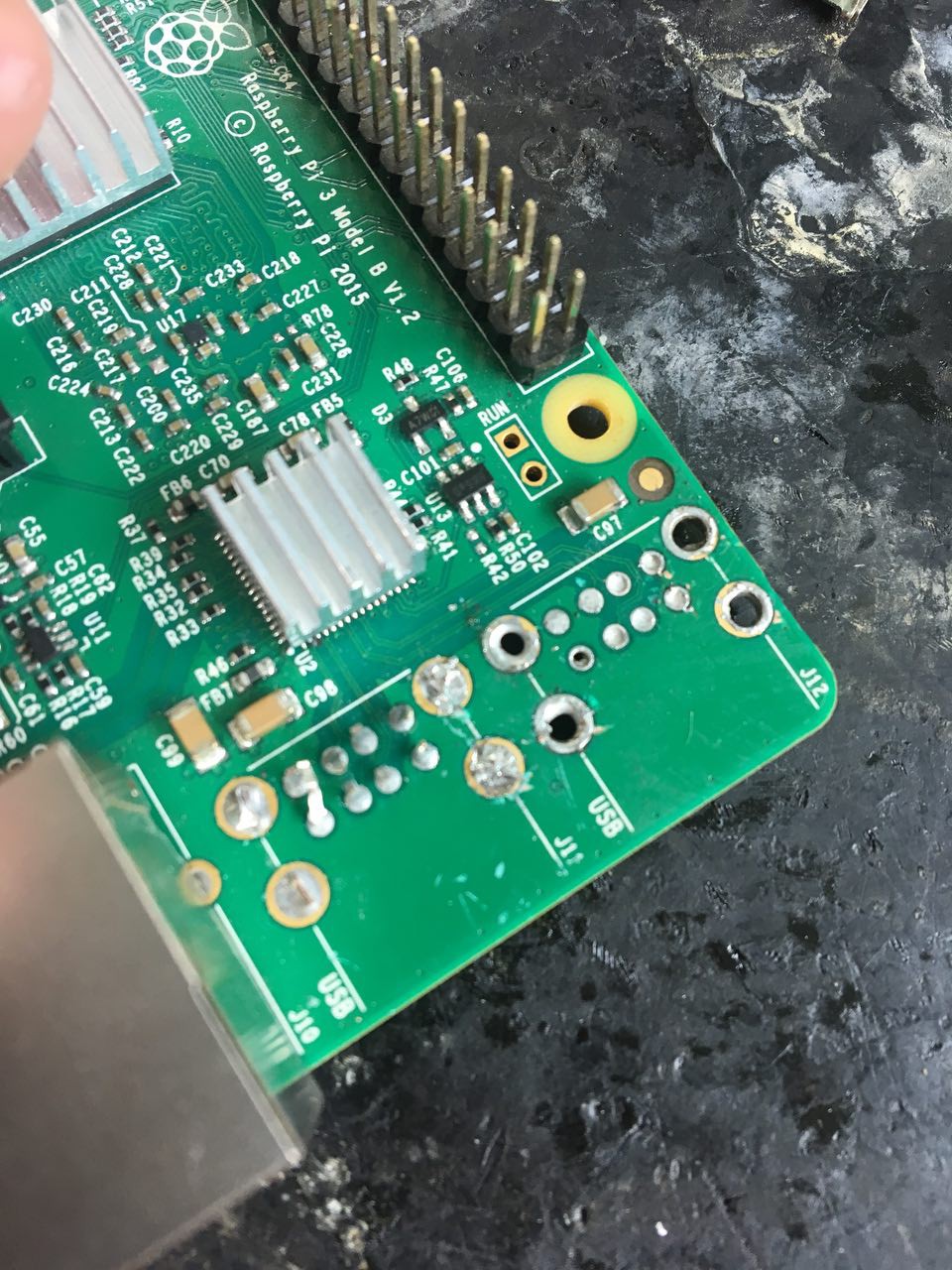
12/26/2017 at 15:00 • 0 commentsThe first thing that i do was removing Ethernet, GPIO headers and the two USB hosts, be careful doing that, if you heat too much you can break the circuit line in board, it's a patiently job.
![]()
![]()
![]()
Viper PRO
Viper PRO is a portable game console built with a Raspberry Pi 3 which is currently running Lakka Operating System.