Keith
Keith-
Slow mode counter circuit
09/30/2023 at 15:08 • 0 commentsThere are designs on the net for this, but they all seem based on a design with a fundamental error.
They asynchronously reset the 8-bit counter when it reaches 207.
This means it cycles through states 0 to 206, then very briefly becomes state 207 before settling in state 0.
Thus you get a divide by 207 counter, which is one count too short.
http://searle.x10host.com/zx80/ZX80nmiVer4.1.jpg
PAL video lines are 64 microseconds long, so the line rate should be 15625 Hz.
The ZX81 CPU clock is 3.25 MHz, so 3,250,000/15,625 = 208.
Detecting 207 is correct for synchronous counters, because they won't change until the end of state 207.
For synchronous counters like the 74HC393, you need to detect state 208, which is actually simpler to do.
207 = CF hex = 1100 1111 binary
208 = D0 hex = 1101 0000 binarySo all you really need to do is detect 1101 on the four most significant bits, because it won't happen until the lower bits have rippled back to zero.
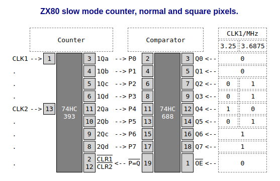
When using the square-pixel 40-column modification, the CPU clock is 14.75/4 = 3.6875 MHz, and the divider must be 236. That is EC hex, 1110 1100 binary.
Rather than build a circuit from simple AND and OR gates, it is much more convenient to use a 74HC688 comparator:
![]()
CLK1 is the inverted CPU clock, and CLK2 is driven by 1Qd.
The divisor rate can be made switchable by having comparator input Q4 = 1 for square pixels and 0 for normal pixels.
Inputs Q2,3,5 are 0 for square pixels and 1 for normal pixels.If you wish to be clever, you could mod your firmware to sense the selection and adjust accordingly. You will need a spare input bit, which you have on D5 of the keyboard input port. This is normally high, so it would be wired to comparator inputs Q2,3,5.
Another bonus is that if you want to run the CPU at any other speed, you simply have to change the comparator inputs Q0-7.
If speed is your demon and you run the CPU at 4 MHz, the divisor is 256 and the counter automatically cycles back to 0 and you won't need a comparator at all.
You will need to check the other logic in the Grant Searle design. Luckily, most tellies are fairly forgiving and will cope with minor deviations from the PAL sync and porch timings.
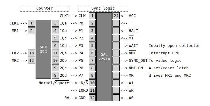
As I'm short on free time, I shall be implementing the slow mode generator in a GAL chip, something like this:
![]()
This will combine the comparator with the sync and porch pulse logic.
The N/S signal selects which one of two divisors to use.
If the comparator outputs are synchronous, then it does have to detect values 207 and 235.
-
Memory map
09/23/2023 at 23:19 • 0 commentsZX81 BASIC, based on Shoulders of Giants improved code, hacked for operation at 7.375 MHz.
Contains two versions, one with normal 32-column text, another with experimental 40-column text.
This is a 32K ROM, use lower or upper 16K in the bottom 16K of the ZX80 memory map.
Both versions include a 2K monitor at 3800 hex.
0000 8K ZX BASIC
2000 2K blank (FF)
2800 2K G007 graphics
3000 2K blank (FF)
3800 2K ZX81 monitor
4000 As first 16K, but with alternative display width.
Connect the ROM A14 to a 1P2T switch, to select display width at reset.
The G007 graphics does not work without the G007 hardware. I just put it there for later experiments.
-
Construction
09/16/2023 at 11:51 • 0 commentsThe ZX80 is more hackable than the ZX81 because all the logic chip signals are accessible.
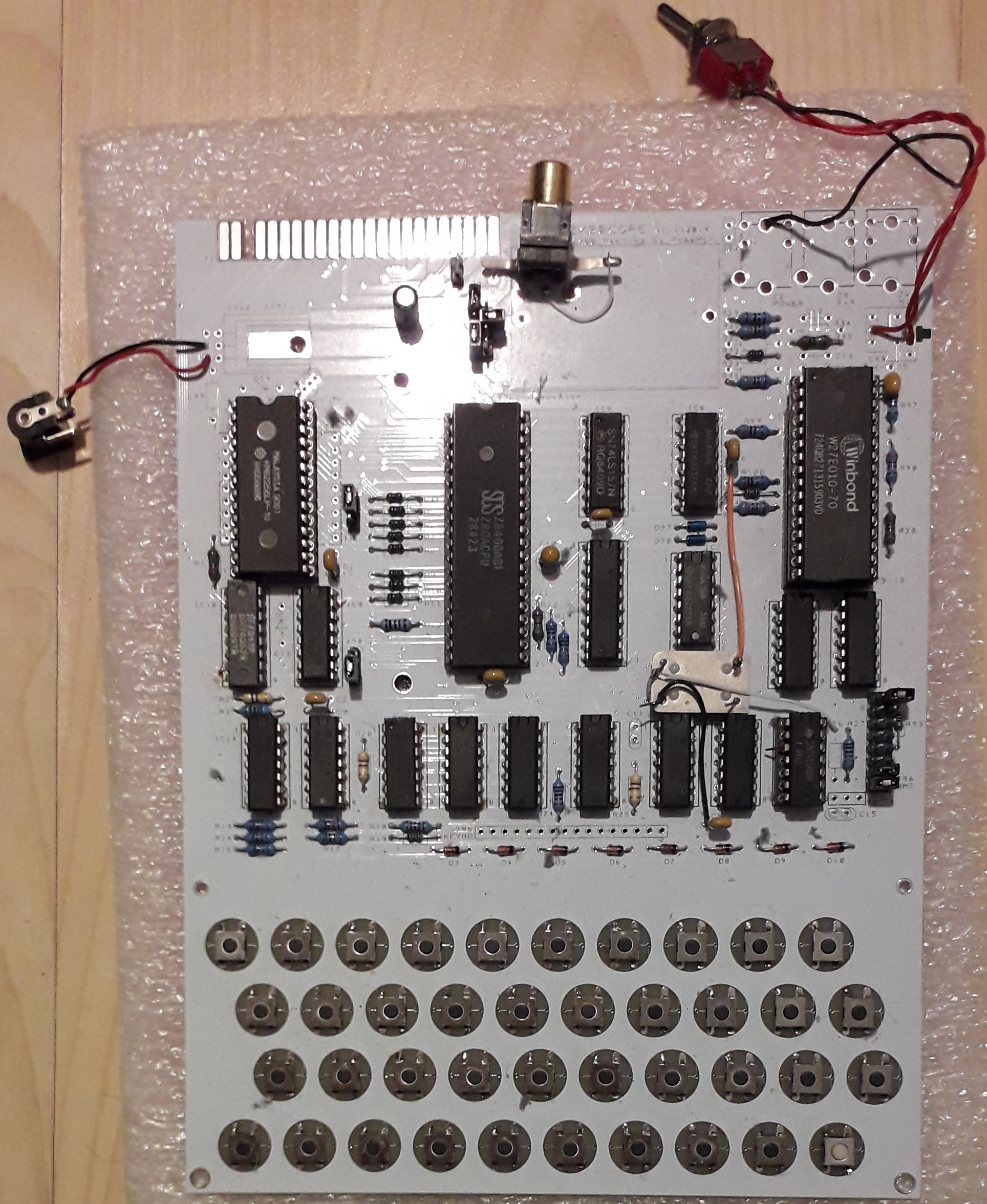
I bought a PCB and populated it with good quality turned-pin sockets and new chips.
I noticed it was still prone to crashing even without an external RAM pack.
I suspected that socket connections were intermittent, especially when the PCB was being flexed by pressing the keyboard.
I removed the sockets of the TTL chips and soldered the TTL chips directly to the PCB. This was a great improvement.
Lessons learnt:
- Sockets are more trouble that they are worth. Avoid them!
- Socket contacts fail when PCBs are flexed. Avoid this.
- Putting the keyboard on the same PCB as socketed chips is a bad idea for the reasons above.
![]()
I fitted a 32K RAM chip, to banish RAM-pack wobble crashes forever.
I fitted tactile switches salvaged from scrap boards. The buttons are low-profile, so they don't click so well when pressed by a finger. Some kind of key tops, or higher-profile keys, would fix this.
For square-pixels, the clock was changed from 6.5 to 7.732 MHz. I used a DIP14 oscillator in a metal can, but changing the crystal would also work and look neater. The rest was firmware modding. I added a SPDT switch to select the standard or alternative firmware. I used my modified ZX81 BASIC firmware, but you could just as easily select ZX81 Forth or anything else.
ZX80 with 40 column text
40-column text, and square pixels mean 45 degree lines look right. Runs 13% faster as well!