Gombe
Gombe-
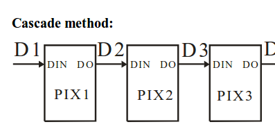
connect with ws2812; LED strips
07/08/2018 at 01:28 • 0 commentsws2812 is an RGB LED which has individually included LED controller.
![]() Each LEDs can be controlled one by one using serial signal.
Each LEDs can be controlled one by one using serial signal.![]()
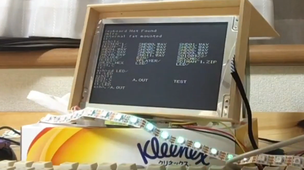
I made a signal using an OC module and DMA and output an Audio port to the LED strip.
---------- more ----------#include <sys.h> #include <file.h> #include <p270256b.h> #define LEDs 60 #define OVERSAMPLEx 4 #define VLEDs (LEDs*OVERSAMPLEx) typedef struct{ unsigned char r; unsigned char g; unsigned char b; } led_t; // ==================== // ======led task====== // ==================== // ===DMA setting=== // *addr ==> OC4RS // trig TMR4 irq // 1byte per event // destination size is 1byte. // src size is `size` // DMA channel 1 and 2 for SD, channel 3 for keyboard, so we use channel 0 to audio.(No more DMA channel;) void initdma(char *addr,unsigned size){ DMACON[SET] = 0x8000; DCH0CON[ORIG] = 0x02; DCH0ECON[ORIG] = (14<<8)|(1<<4); DCH0SSA[ORIG] = ((unsigned)addr) & 0x1FFFFFFF; DCH0DSA[ORIG] = ((unsigned)OC4RS) & 0x1FFFFFFF; DCH0SSIZ[ORIG] = size; DCH0DSIZ[ORIG] = 1; DCH0CSIZ[ORIG] = 1; DCH0INT[CLR] = 0x00FF00FF; // DCH0CON[SET] = 0x80; } #define CLRFLG DCH0INT[CLR] = 0x00FF00FF #define ISHALFDONE DCH0INT[ORIG] & 0x40 #define ISALLDONE DCH0INT[ORIG] & 0x80 // ===PWM settings=== // use timer3 // use OC4 // pwm max duty = 0xFF (8bit) // output PB13 void setuppwm(void){ RPB13R[ORIG]= 5; PR3[ORIG] = 60; TMR3[ORIG] = 0; T3CON[SET] = 0x8000; OC4CON[ORIG]= 0x000e; OC4CON[SET] = 0x8000; } unsigned char ledtransbuff[LEDs*24+60]; void initled(void){ setuppwm(); initdma(ledtransbuff,sizeof(ledtransbuff)); } void calcdata(led_t *leds){ int i,j; int t; for(i=0;i<LEDs;i++){ t = 0; for(j=0;j<OVERSAMPLEx;j++) t += leds[i*OVERSAMPLEx+j].g; t /= OVERSAMPLEx; for(j=0;j<8;j++){ ledtransbuff [i*24+j]=(t&(1<<(7-j)))?40:15; } t=0; for(j=0;j<OVERSAMPLEx;j++) t += leds[i*OVERSAMPLEx+j].r; t /= OVERSAMPLEx; for(j=0;j<8;j++){ ledtransbuff [i*24+j+8]=(t&(1<<(7-j)))?40:15; } t=0; for(j=0;j<OVERSAMPLEx;j++) t += leds[i*OVERSAMPLEx+j].b; t /= OVERSAMPLEx; for(j=0;j<8;j++){ ledtransbuff [i*24+j+16]=(t&(1<<(7-j)))?40:15; } } } void resend(led_t *leds){ calcdata(leds); while(!(ISALLDONE)); DCH0CON[SET] = 0x80; CLRFLG; } void send(led_t *leds){ calcdata(leds); DCH0CON[SET] = 0x80; CLRFLG; } void pattern1(int p,int l,led_t c,led_t *led){ int k; l*=OVERSAMPLEx; c.r /= l; c.g /= l; c.b /= l; for(k=0;k<l;k++){ led[(p+VLEDs+k)%VLEDs].r += k*c.r; led[(p+VLEDs+k)%VLEDs].g += k*c.g; led[(p+VLEDs+k)%VLEDs].b += k*c.b; led[(p+VLEDs+l+k)%VLEDs].r+=(l-k)*c.r; led[(p+VLEDs+l+k)%VLEDs].g+=(l-k)*c.g; led[(p+VLEDs+l+k)%VLEDs].b+=(l-k)*c.b; } } int main(int argc,char **argv){ int i,k; led_t led[LEDs*OVERSAMPLEx]={{0,0,0}}; initled(); send(led); while(ps2keystatus[0xD]); led_t col[]={{100,100,100},{200,100,0},{0,200,100}}; for(i=0;i<VLEDs/3;i++){ led[i].r = 150; led[i].b = 150; led[i].g = 150; } resend(led); wait60thsec(30*8); for(i=0;i<VLEDs/3;i++){ led[i].r = 0; led[i].b = 0; led[i].g = 0; } resend(led); return 0; while(1){ for(k=0;k<VLEDs;k++){ for(i=0;i<VLEDs;i++){ led[i].r = 0; led[i].b = 0; led[i].g = 0; } for(i=0;i<sizeof(col)/sizeof(col[0]);i++){ pattern1(k+i*90,4,col[i],led); } resend(led); if(ps2keystatus[0xD])break; } resend(led); if(ps2keystatus[0xD])break; } // Return to quit. wait60thsec(1); return 0; } -
2048, puzzle game
01/14/2018 at 00:41 • 0 comments
2048 a puzzle game 2048(wikipedia)
is a kind of puzzle games, famous for smartphone applications. It is simple but difficult. forked from https://github.com/mevdschee/2048.c
Text mode has characor color. But this text video system is not supported background color for each charactors. So I put colored space instead of white space.
-
Add Graphic mode
01/06/2018 at 11:30 • 0 commentsGraphic mode is comming soon! This mode is very important to develop graphics games. Size of GRAM is about 29KB. Screen size is 256x224. 4bit-color surported. (dynamic palette)
Or you can use PCG (see TETRIS for example..).
This is demo of Graphic mode.(Video player)
This sample also incluing audio player. This `MachiKania Game Board` incluing audio output, I use OC module for PWM and DMA to generate audio signal. DMA stands for Dinamic Memory Access. 32K sampling per seconds, 8bit 1ch.
Double buffering memory is not enough(lack of RAM), so bottom of screen is fricking ; )
Native-C PIC32 color video on TV
Native C language environment with the color video system. including a text editor, compiler, linker, assembler. It likes RetroBSD.
 Each LEDs can be controlled one by one using serial signal.