DIY Spot Welder for Creating Battery Packs
Building a Spot Welder for 18650 battery packs is an interesting and challenging adventure. How to over-engineer a spot welder.
Building a Spot Welder for 18650 battery packs is an interesting and challenging adventure. How to over-engineer a spot welder.
To make the experience fit your profile, pick a username and tell us what interests you.
We found and based on your interests.
This is not a super elaborate code that controls the universe and everything.
Instead it's just a very simple piece of code that allows driving a display, debouncing a switch, reading two potentiometers, and drive a relay. That's it.
I use busy waiting to execute the read potentiometer values and I use very simple line drawing to visualize the pulse pattern.
I divided the welding process into two steps:
During my initial tests and from what I have read online in several articles, the typical pre weld time is around 50 ms and the typical weld time is around 100 ms. I used this as a base line since most people don't seem to weld with 1750 Watts. I wanted to be able to adjust my welding times between 25 ms and 275 ms by adjusting two potentiometers. I also added a cooldown time in between the two weld actions of 250 ms. That's a pure guess and should have been adjustable with another potentiometer as well but I didn't see the immediate need for it. If you need it, please add a third pot to the code and to your welder. I don't think it's necessary for making battery packs.
#include <Adafruit_GFX.h>    // Core graphics library
#include <Adafruit_ST7735.h> // Hardware-specific library
#include <SPI.h>

// For the breakout, you can use any 2 or 3 pins
// These pins will also work for the 1.8" TFT shield
#define TFT_CS   10
#define TFT_RST  9
#define TFT_DC   8

#define TFT_SCLK 13
#define TFT_MOSI 11

#define MINWELDTIME   25
#define MAXWELDTIME   250
#define COOLDOWNTIME  250
#define ADCRESOLUTION 1023
#define GRAPHDIVIDER  7 // devides the values for displaying the graph to something that can be displayed

// use the hardware SPI pins (for UNO thats sclk = 13 and sid = 11) and pin 10 must be an output.
Adafruit_ST7735 tft = Adafruit_ST7735(TFT_CS,  TFT_DC, TFT_RST);

// constants won't change. They're used here to
// set pin numbers:
const int buttonPin = 5;    // the number of the pushbutton pin
const int ledPin = 12;      // the number of the LED pin
const int relayPin = 2;     // the number of the relay pin
const int preWeldSensorPin = A0;   // the number of the potentiometer ADC pin
const int weldSensorPin = A1;   // the number of the potentiometer ADC pin

// Variables will change:
int ledState = LOW;         // the current state of the output pin
int buttonState;             // the current reading from the input pin
int lastButtonState = LOW;   // the previous reading from the input pin
int preWeldSensorValue = 0;         // variable to store the value coming from the potentiometer
int weldSensorValue = 0;         // variable to store the value coming from the potentiometer
bool redrawGraph = true;      // Did we change the times and need to redraw the graphs?

int lastPreWeldTime = 0;  // Storage for the previously set weld times
int lastWeldTime = 0;     // So that we don't run into flickering numbers on the display

// the following variables are unsigned long's because the time, measured in miliseconds,
// will quickly become a bigger number than can be stored in an int.
unsigned long lastDebounceTime = 0;  // the last time the output pin was toggled
unsigned long debounceDelay = 50;    // the debounce time; increase if the output flickers

void setup() {
  pinMode(buttonPin, INPUT);
  pinMode(ledPin, OUTPUT);
  pinMode(relayPin, OUTPUT);

  // set initial LED state
  digitalWrite(ledPin, ledState);
  digitalWrite(relayPin, HIGH);

  Serial.begin(115200);     // opens serial port, sets data rate to 115200 bps
  Serial.println("Spot Welder Version 0.1 - Timo Birnschein - MicroForge 2018");
  Serial.println("email: timo.birnschein@microforge.de");

  displayInitScreen();
}

void loop() {
  // read the value from the sensor:
  preWeldSensorValue = analogRead(preWeldSensorPin);
  weldSensorValue = analogRead(weldSensorPin);

  // Read analog signal to determine time to weld
  int preWeldTime = (int)((float)MINWELDTIME + (((float)MAXWELDTIME...
Read more »
In order to weld metal to metal with a spot welder two things are important:
The first bit can be achieved by hinging both arms individually and make both of them spring loaded. I didn't have any springs to I used a ring of ninjaflex for 3D printers instead. Works great! (thus far).
The time to weld the material is another story that I will cover in the software log.
I wanted to create an enclosure that is easy to move around, has exposed arms, a display, a fuse behind a service bay, the potentiometers, as well as my favorite 86ct wall switch from Home Depot. It also needed to provide enough strength to house the heavy transformer as well as the double hinged arms that really shouldn't move at all - except vertically.
It's essentially a box. It has everything described above and it made from sturdy 5mm plywood from Home Depot. The front is only 3mm plywood because I needed to be able to mount the potentiometers as well as the display properly. The rest is decoration.
On the inside, there is the fuse block, the $1 wall charger from Dollar Tree (I really went all in here!) as well as the $2 Arduino relay. I mounted everything to the front plate that is either 5V or needs to be swapped out ones in a while.
The hinge mechanism is equally simple. I just needed to constrain the two arms in all axis except one. This is possible with stiff side plates and a center plate to keep them apart which is why there are three plates glued to the top cover instead of just the outer two.
In the end it pretty much looked exactly the same in real life:
I lasered everything out on my modified K40 China laser that I couldn't live without and started putting the enclosure together. Unfortunately, I ran out of 12x3mm screws so I had to revert back to gluing instead of screwing. Not exactly what I wanted but it works as well. It made the process only marginally more complicated and it's still very serviceable and cheaper.
I put a switch inside the hinge mechanism to auto-fire the welder as soon as I pressed the electrodes against the material to weld with sufficient force.
The resulting enclosure looks cool on my desk and really works well. I can put the welder where ever I want. The wall switch really works well on the front as well.
The display is easily readable from the operators point of view. The contrast is actually very nice when viewed from the front.
Shortly after everything was put together I started to make some test welds. Of course! I couldn't wait to test my software and I was very eager to learn two things:
To my big surprise the answer to both these questions was very positive! Everything works! I even started dialing in the durations for both pre-weld and weld since my 0.2x8mm Nickel strips needed a lot less time to weld than my 0.75mm steel strips. Not exactly surprising.
What I really liked about this was the test to rip the welded strips apart.
I couldn't.
I used two pliers and all the force I was able to exhibit and only one welding spot popped off and left a hole! DANG!
In the end I tested my new tool with $1 batteries (8 for $1 - guess from where). I just wanted to weld something. The batteries are utter crap and I would never buy them again for anything serious but for a welding exercise they seemed perfect.
They weren't.
Apparently, the negative pole of the battery is just a cap and separates itself from the battery when the heat shrink melts. Its literally not connected to the battery except by touching the surface. However,...
Read more »Trigger happy I was when I first tested the transformer for spot welding. I literally plugged it into the mains power with a switch and turned it on and off in rapid succession. This works surprisingly well and I would test like this again if I have no other choice.
However, I have a choice since I love building embedded systems.
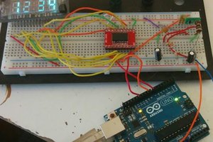
I have some Arduino Nano flying around because it's by far my favorite form factor for a micro controller project and bloody cheap. I quickly put together a bead board to test my control scheme with the actual target hardware: A $2 Arduino relay. Not exactly the most durable solution to switch 15A under load. Anyways. We will see how long it will last and if swapping it out is more of a hassle than designing a direct replacement TRIAC circuit.
The dry run worked and I started designing an actual PCB.
I wanted to mount the display directly to the board to avoid wires as much as possible. It was supposed to go onto the back of the PCB while the Arduino sits on the front side. Other than that, there is not much to it. Two potentiometers, one switch that needs to be pulled to ground as well as the relay circuit. That's it.
Certainly not a pretty board but it took me less than 2h to design it and 45 minutes to mill it on my PCB mill. Talk about rapid prototyping! I just wanted to get this over with because I was running out of vacation days.
I put the board together and tested the design and I extremely happy when it powered up and worked right away.
I love my PCB mill and I'm very happy with the results even though I need to make my restrings for vias and pads significantly larger from now on. It was also a mistake to drill the holes smaller than 0.8mm. Unfortunately, Eagle is still a bit dumb and gives very inconsistent results when making restrings larger in the design rules and then using copper filling around the traces and pads. Apparently, you can make restrings larger but the clearance around the pads won't automatically grow. As a result you will manually adjust the spacing around the traces and vias/pads but that will cause a lot longer milling times and also doesn't work with ground (GND) vias/pads for some awkward reason.
"I think I want to build an eSkate.."
"Why?"
"Because I think the commercial versions are too expensive and don't pack enough range for actually being usable for commuting"
"... great! I guess ..."
If you had a conversation like that if your life, you're very likely to have one of these spot welders somewhere in your workshop. Spot welders. Why a spot welder?
It's simple:
With a spot welder your can weld metal to metal without actually adding material. You just melt both materials and mix the viscose metals into one object. It's actually that easy.
Spot welding comes in two variants (as far as I know):
When I started researching material for electric skate boards there were two types of people. One is using lipos straight from a hobby store and one is going the extra mile to use 18650 or bigger batteries and make their own packs. Both works well. In fact, it seems easier to identify shitty lipos from HobbyKing than shitty 18650s even from sources like Amazon or ebay because people know them already and there are not as many counterfeits.
However, people using the 18650s are convinced it's the better battery technology. They are widely used in laptops and Tesla's and many other electric vehicles out there. So why not use genuine 18650 cells and make a great high power pack? Because you need decent tools to make the actual pack. Like a spot welder, a long strip of Nickel as well as a decent battery management system to keep all individual cells balanced. Always.
So, ok. What do I need for making a spot welder:
All of the above is relatively easy to obtain, starting with the transformer.
Most people salvage their transformers from old microwaves. People also say that it should have more than 1000 Watts. I found the latter to be untrue. The microwave I stripped was only 750 Watts and the current seemed to have been limited by the use of magnetic shunts inside of the transformer that I could remove. It turns out, my transformer runs at 14.5 Amps during welding and at 4.5 Amps when free flying after removing the magnetic shunts.
P = U x I gives us 120V x 14.5 A = 1.740 Watts! Geeeeezzz! Far more than enough!
My configuration has only 2 windings on the secondary coil and an unknown number of windings on the primary coil. However, what I do know is that 120 VAC get transformed down to 2VAC! That's a factor of 60!
Considering that the primary coil draws 14.5 Amps during welding, this should translate (x60) to 870 Amps on the secondary coil during welding.
If you look at the wire you are supposed to use for this type of current you will end up with something that is essentially unusable and unobtainable. Not surprisingly, most people just use some "thick wire" to build their welders and of course will never achieve these currents during their spot weldings. The internal resistance of the wire itself is just too high and the voltage will break down.
However, I was able to acquire "1 AWG" which is rated for a max current rating of somethingsomething 200 Amps continuous. That seems ridiculously low considering the thickness of the material and having worked with RC cars before where something...
Read more »
Create an account to leave a comment. Already have an account? Log In.
Chào. tôi cần tập tin hex. và tệp pcb của bạn. Bạn có thể chia sẻ? Nếu có thể, hãy gửi cho tôi. tungvy3@gmail.com. Cảm ơn nhiều
Become a member to follow this project and never miss any updates

 Brad Arnett
 Josh
Josh
 jeff.ballard.86
 Timescale
great project, don’t suppose you have a bom laying around?