Close
0%
0%

Toddler's Cyberdeck

I'm built a cyberdeck for my son. He was 2 when I built it. He's still using it today.

Public Chat
Similar projects worth following
My son likes to press buttons and flip switches. If there's a remote, he grabs it. Windshield wipers in the car? ON. Power switch? ON OFF ON OFF ON OFF ON OFF...
So I'm doing what any hacker dad would do... building him a box of switches.

THE TODDLER CYBERDECK.

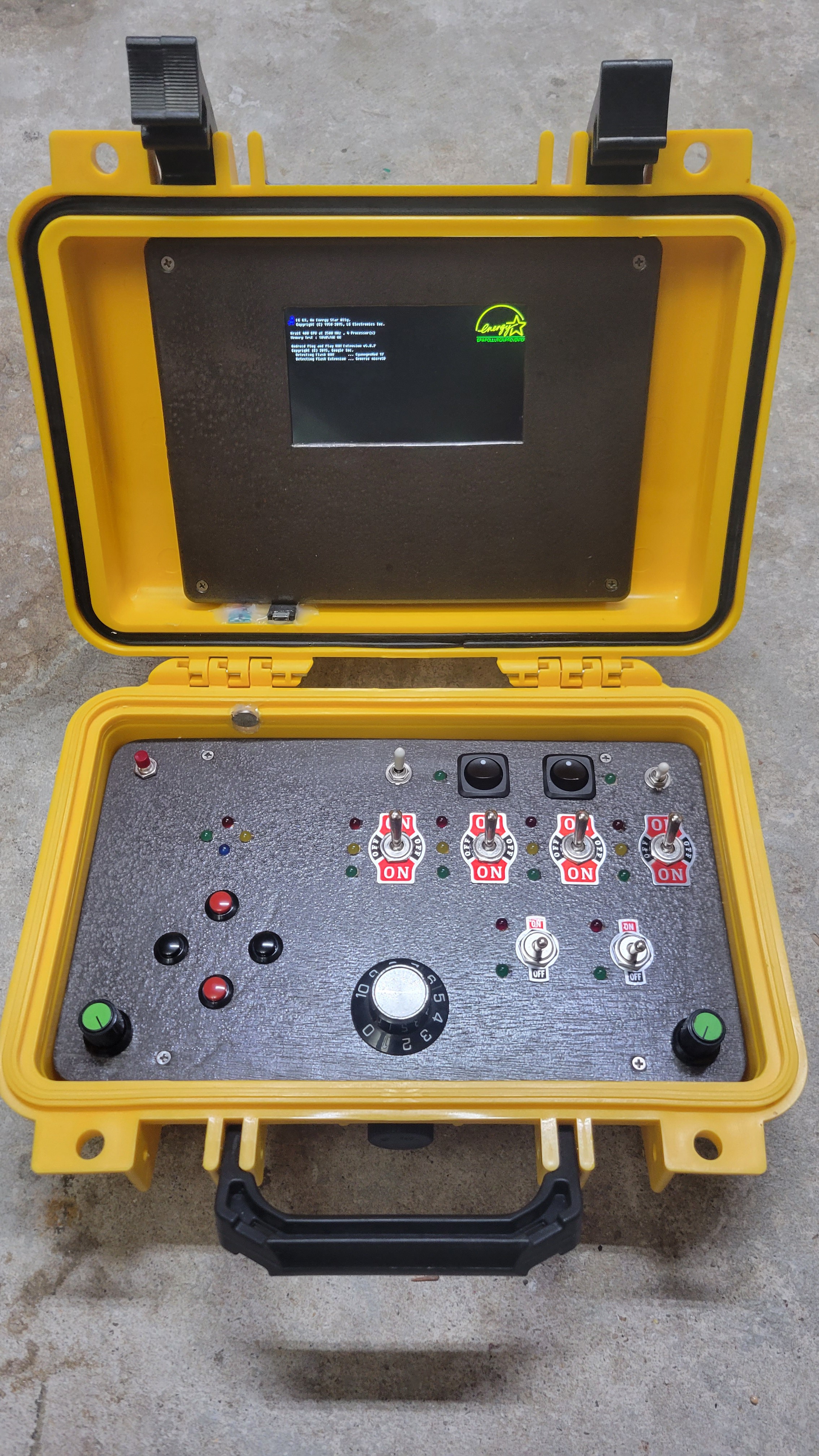
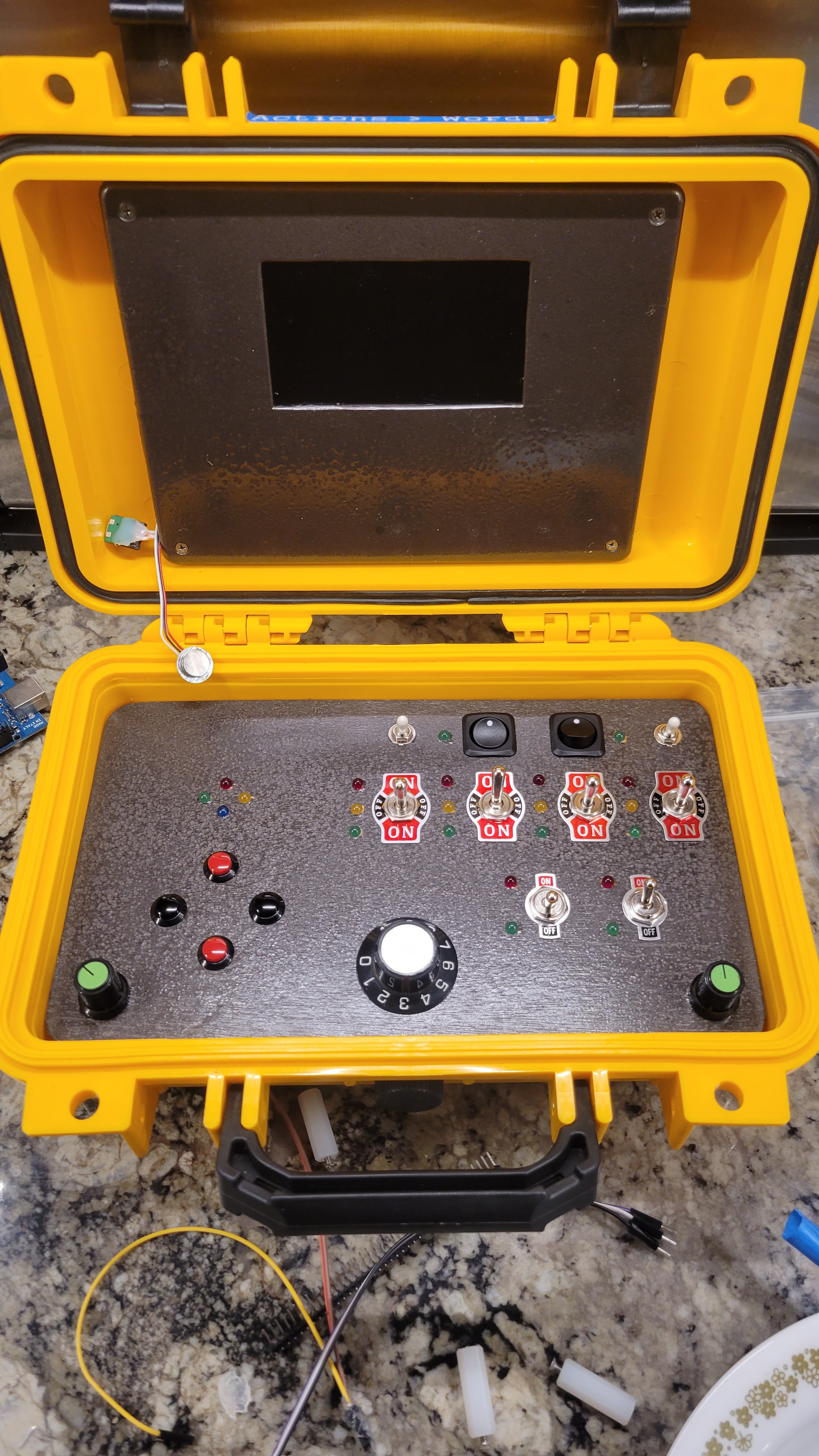
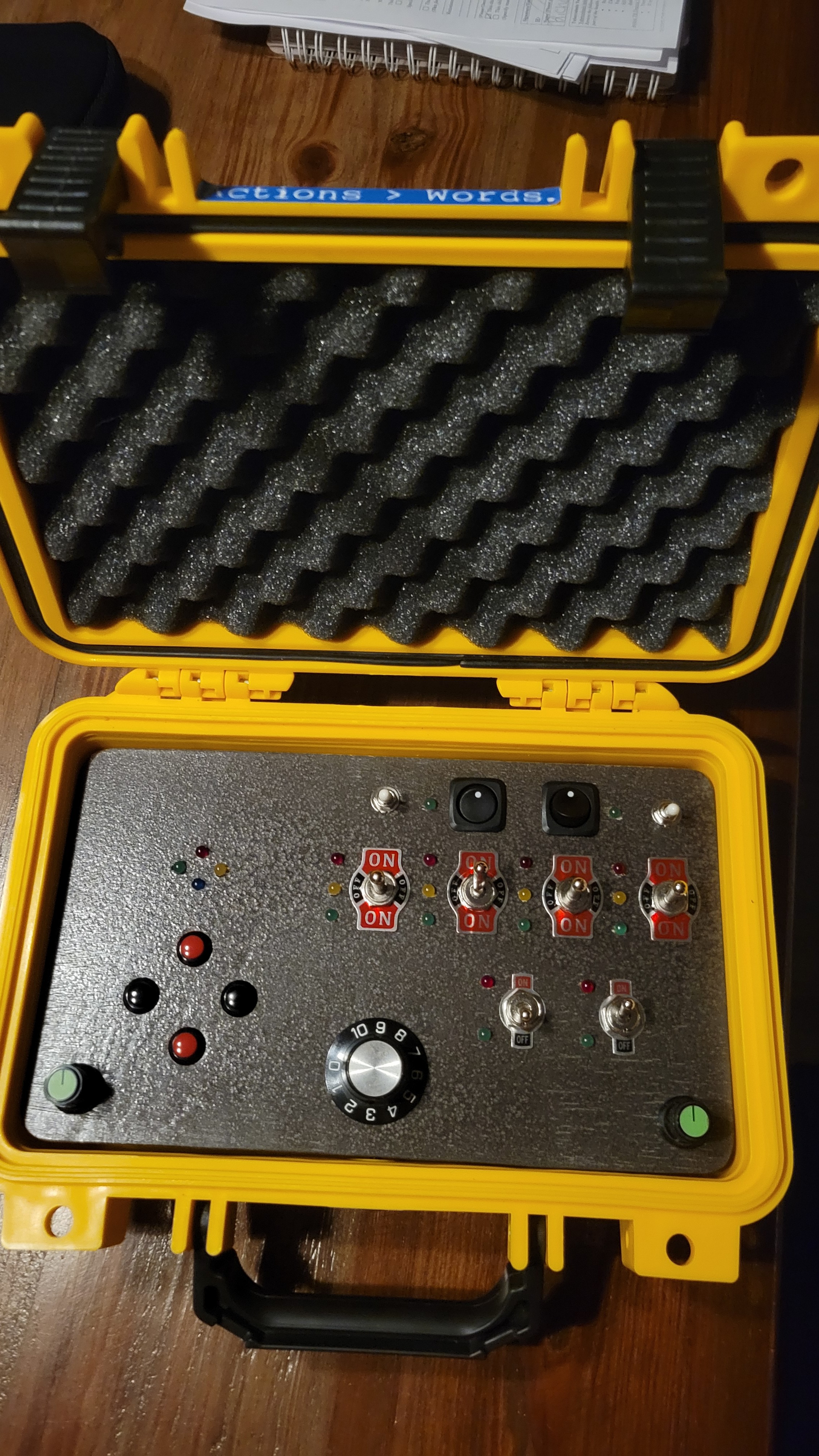
There are two parts to the finished cyberdeck: the lid contains a repurposed all-in-one lcd video promotional player, mounted in a spare plastic enclosure lid top for a bezel. The bottom of the enclosure contains a bunch of switches, buttons, and LEDs, all driven by an Arduino and powered by 2x 18650 lipo cells. There's no link between the lid and the base, although early research indicates I could get them to talk in a future upgrade!
99% of code was written by ChatGPT. See the conversation in the link below.
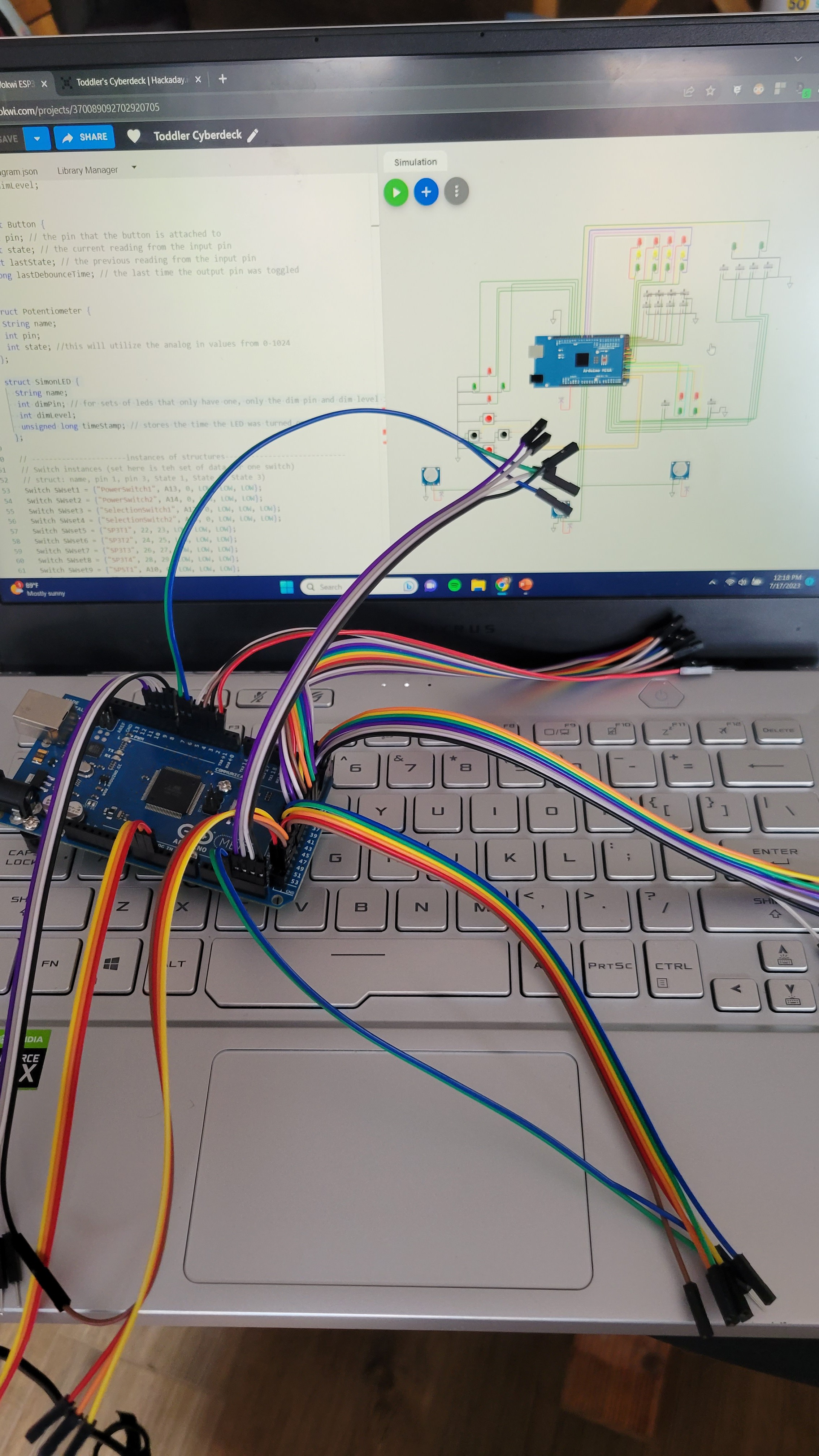
All code and schematic was simulated and troubleshot on wokwi.com (see link below).

The project is simple... but made to grow!

Revision Log:

2023/08/15 - V0.1 - Original release, Functioned well but burned through batteries
2024/08/18 - V0.2 - Added power save functionality (messy but works)

Overview

There are two main parts to this project: The lid is a simple media player "up-cycled" to be a foux-display for the "cyberdeck". The base is the real interactive portion, with switches, knobs, buttons and LEDs.
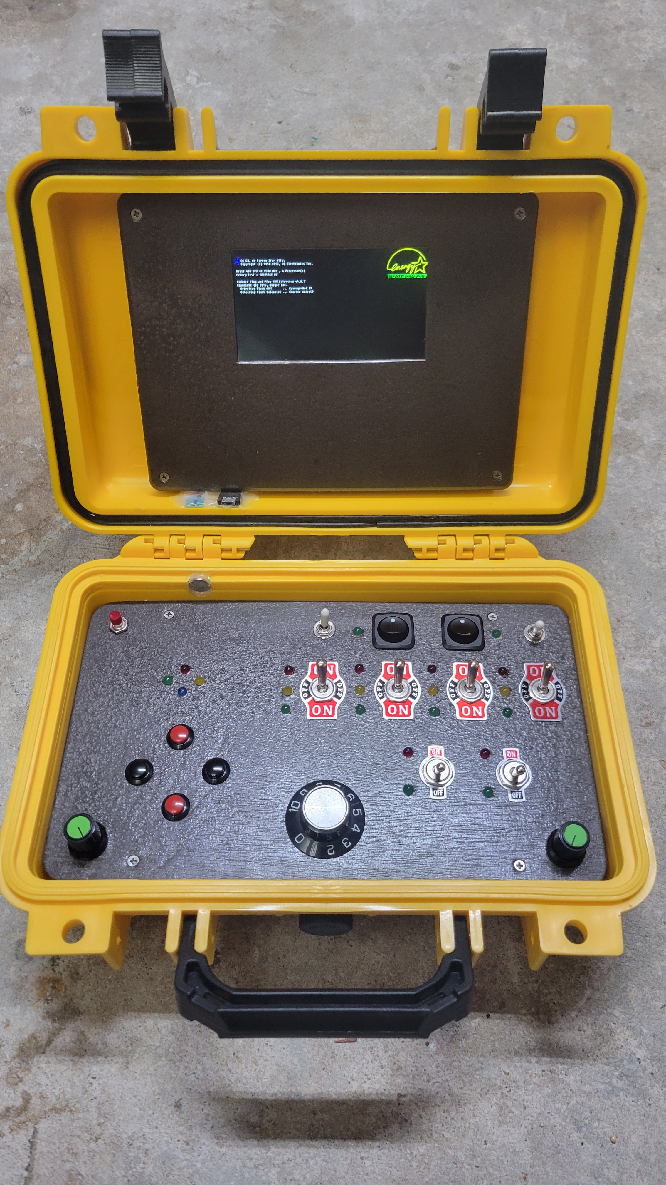
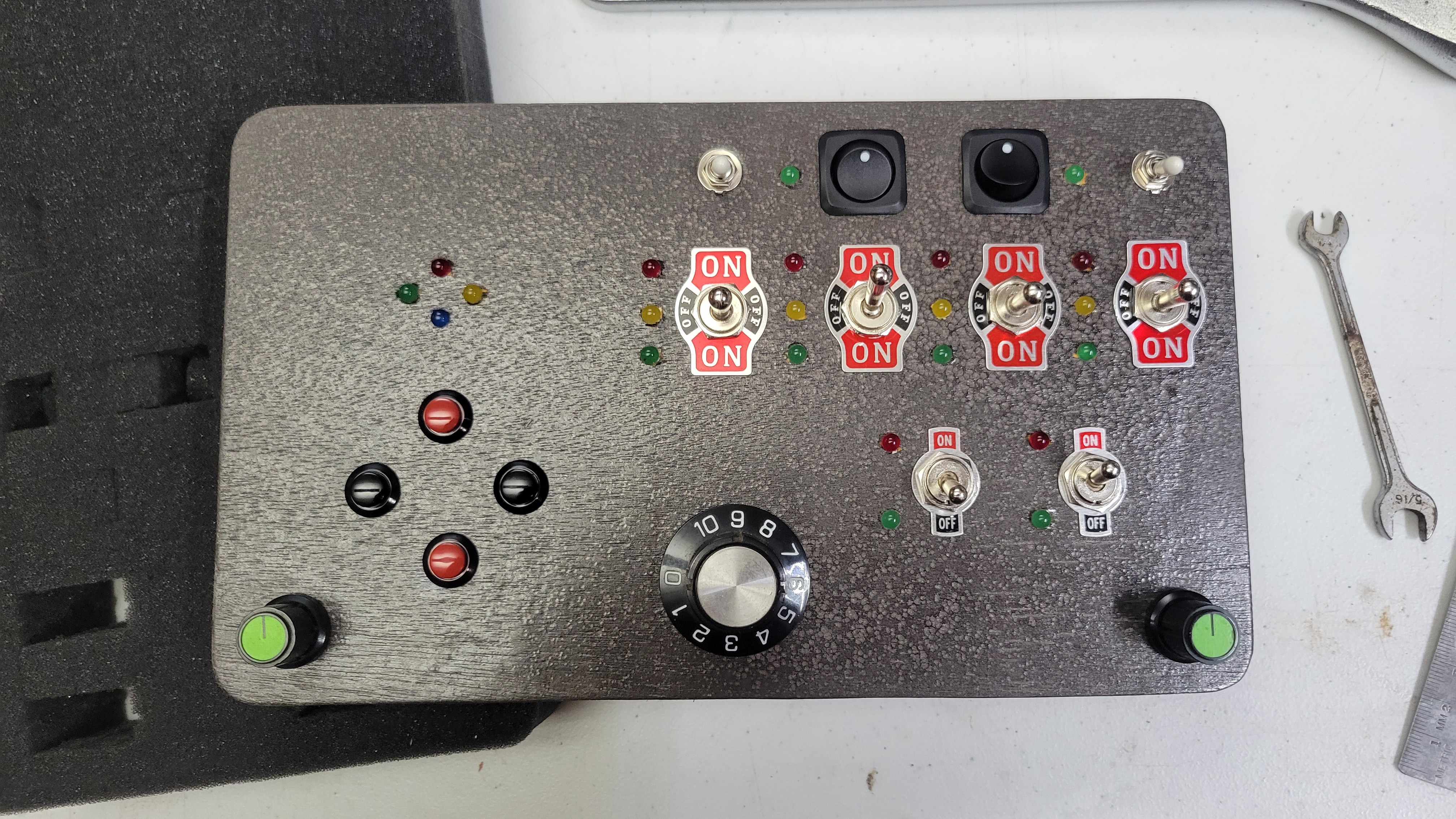
Finished cyberdeck image
Finished Toddler Cyberdeck
 

The Lid:

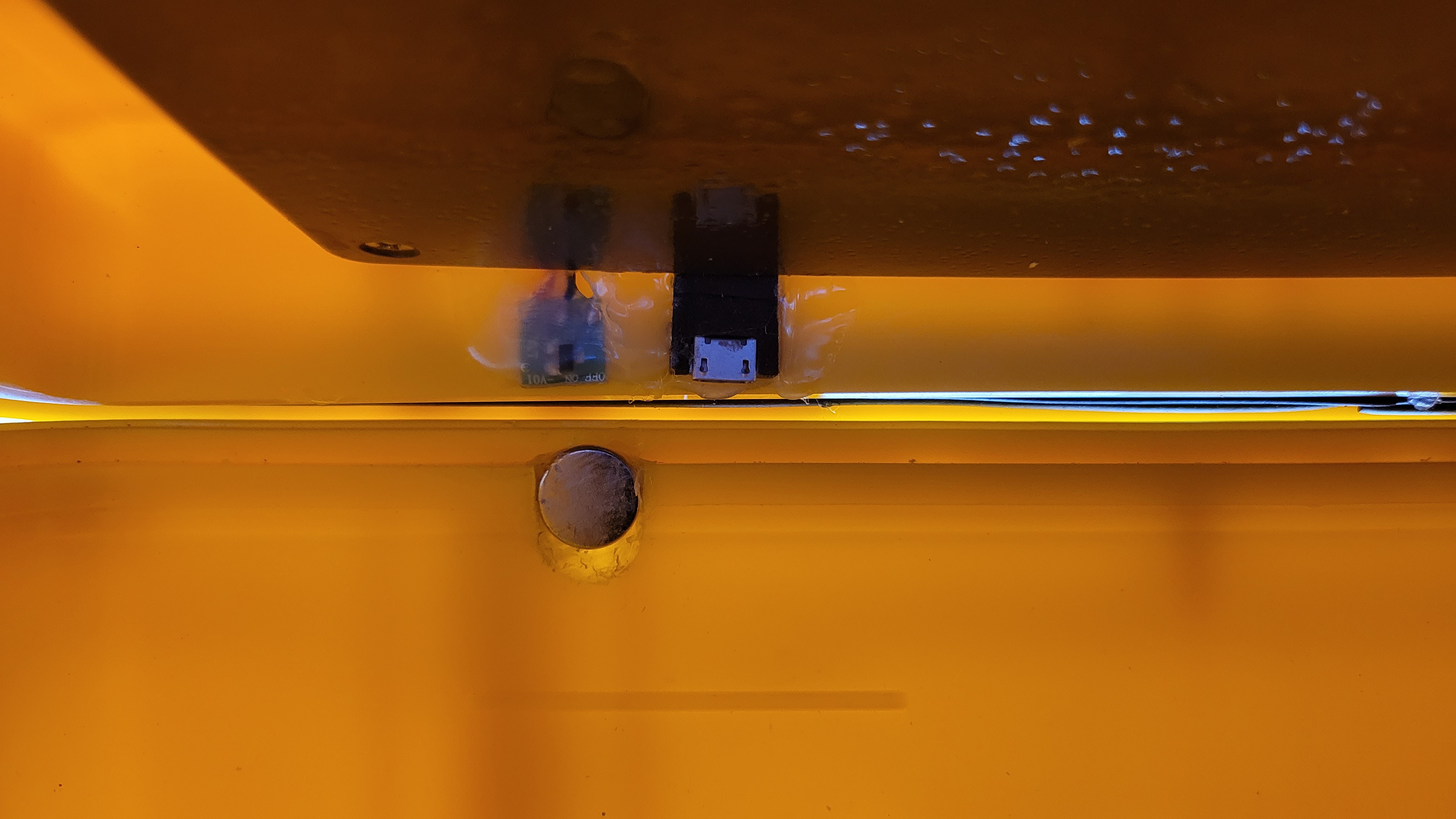
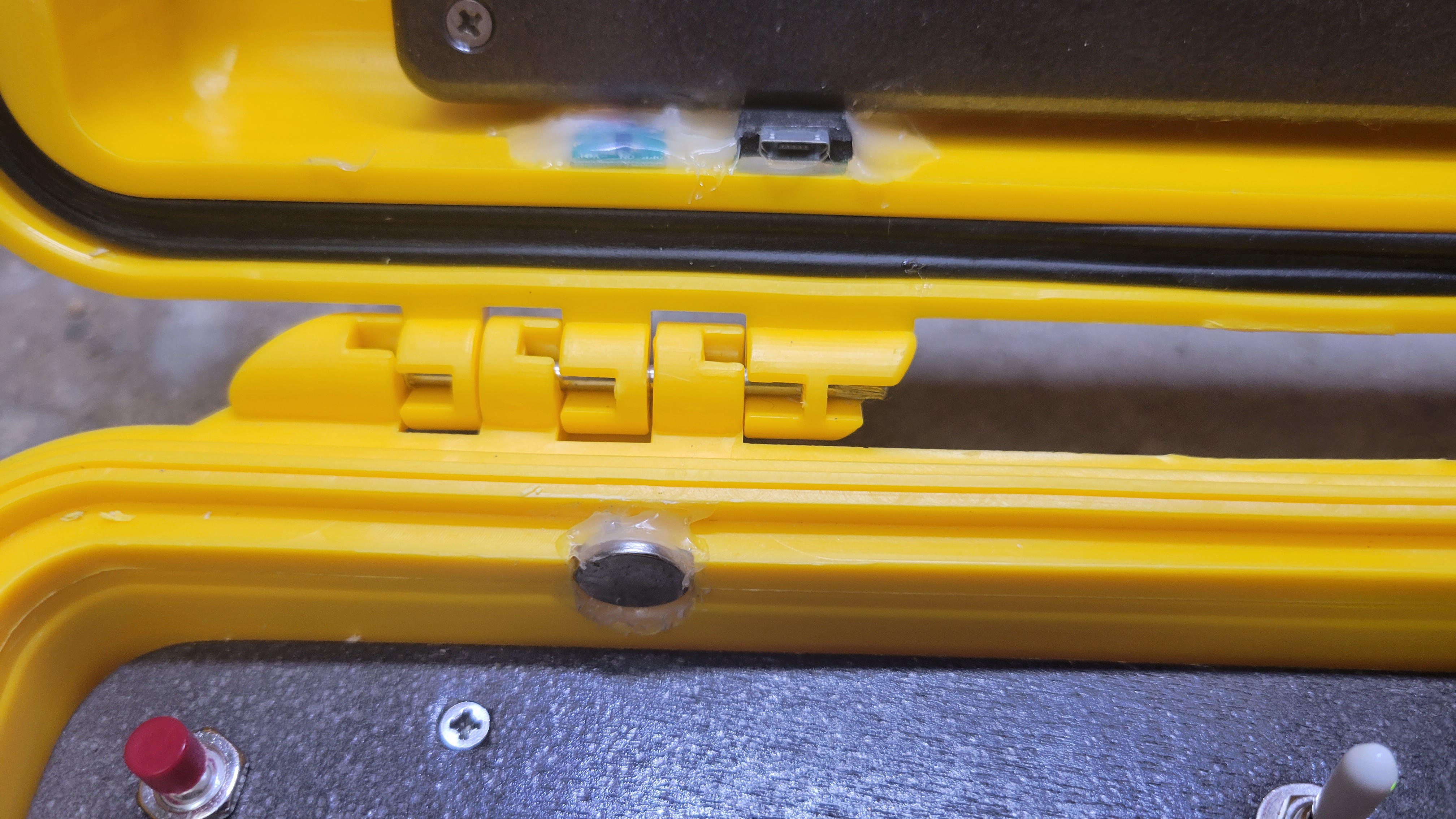
The lid contains the up-cycled guts of a video promotional card that I got in the mail. It's a V100-based SBC with 128M flash, low-res LCD, attached LIPO cell, and 3 buttons for play, next, and previous, as well as a magnetic sensor to turn it on when the lid is open and off when shut. The usb port is hot-glued next to the magnetic sensor at the bottom left in order to charge it and load different videos if I want. For now, the buttons are just hot-glued on the back and inaccessible. 

The Base: 

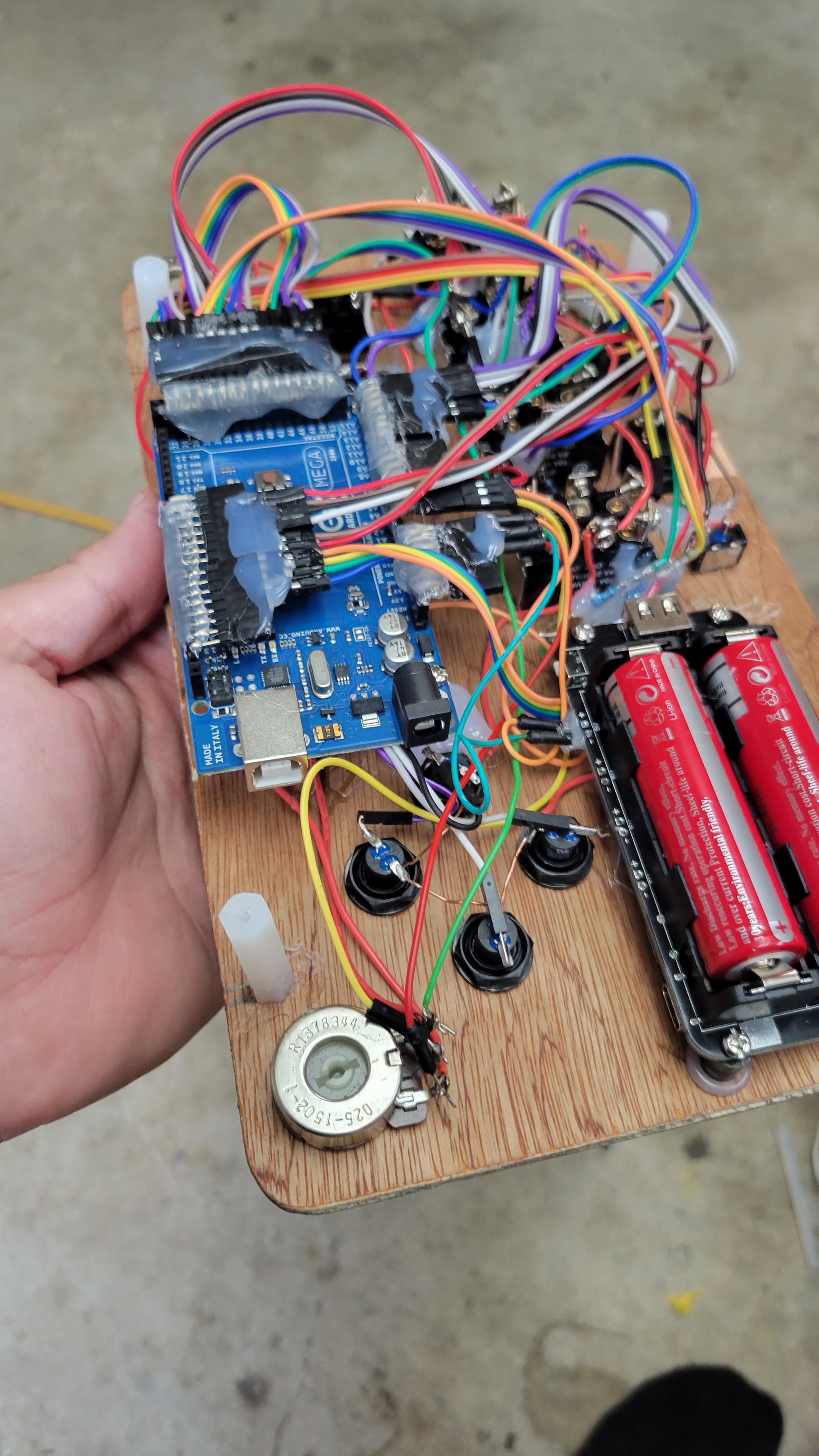
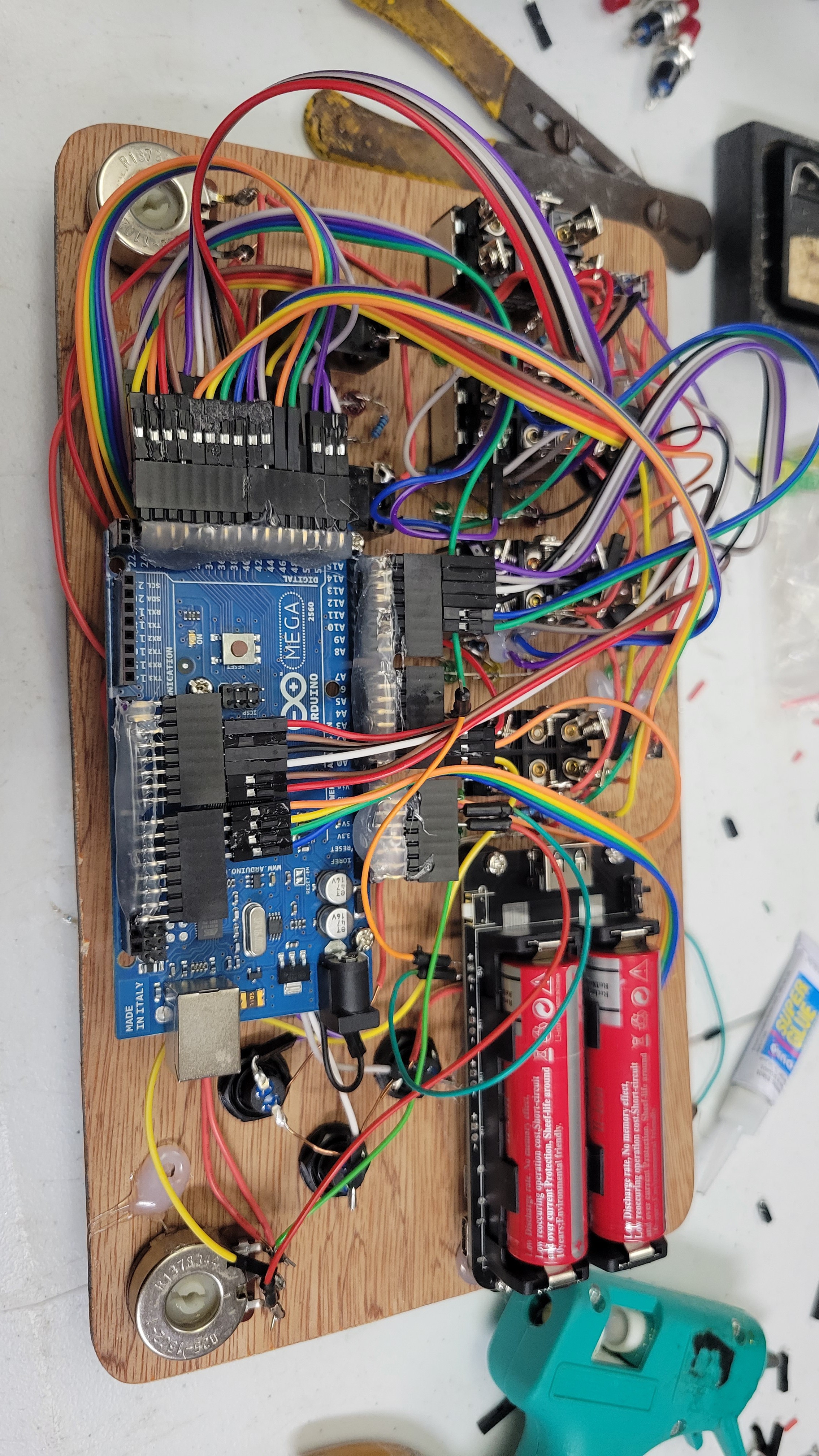
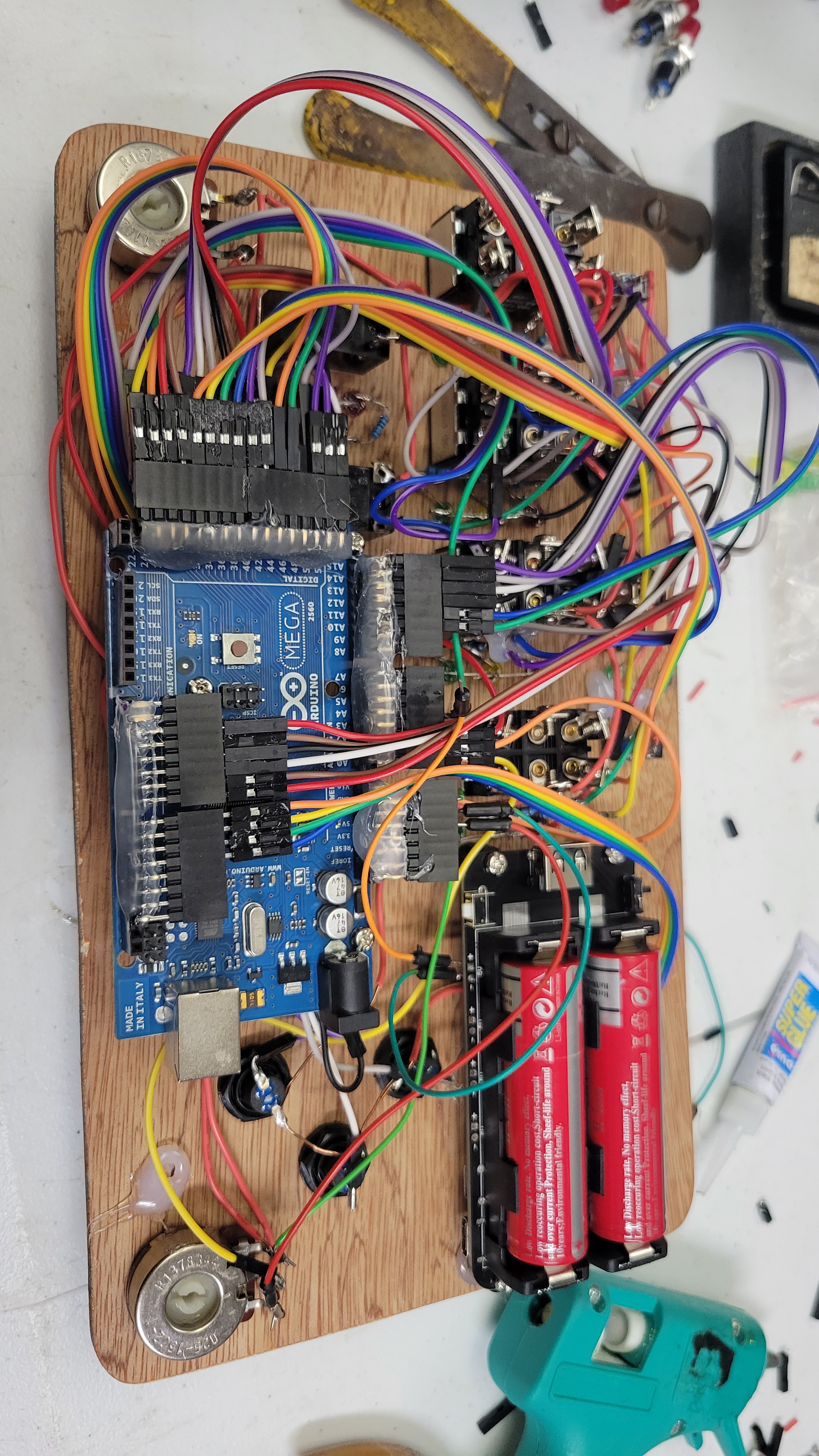
The main interactive portion is all contained in the base. It houses an Arduino Mega 2560, as well as a power supply that holds 2x 18650 cells in parallel, with built in charge circuit, and 3.3v and 5v boost regulated outputs. I am only using the 5v output. The power supply has a low current sleep-mode that is currently not being utilized, but even if this thing stays on, those cells will take a long time to discharge. 

Interactive and Upgradeable 

Hardware Design Basics
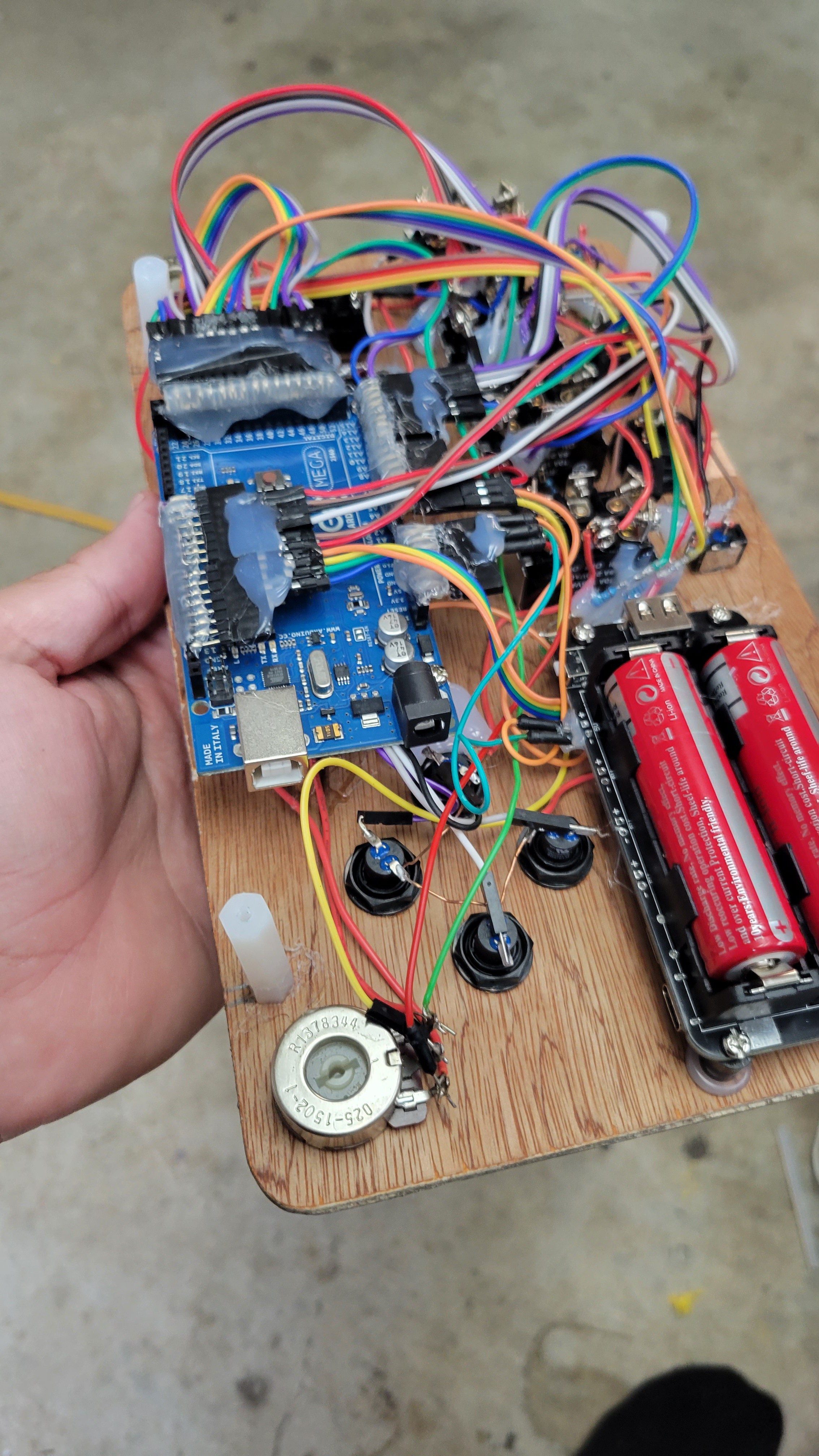
Hidden Mess
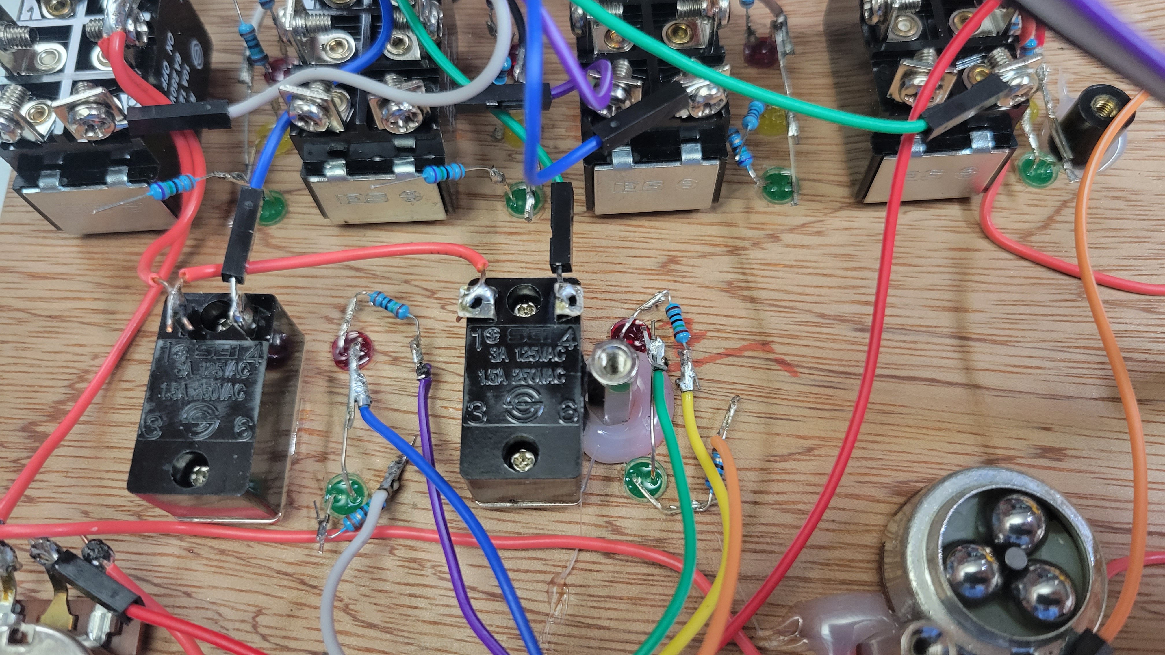
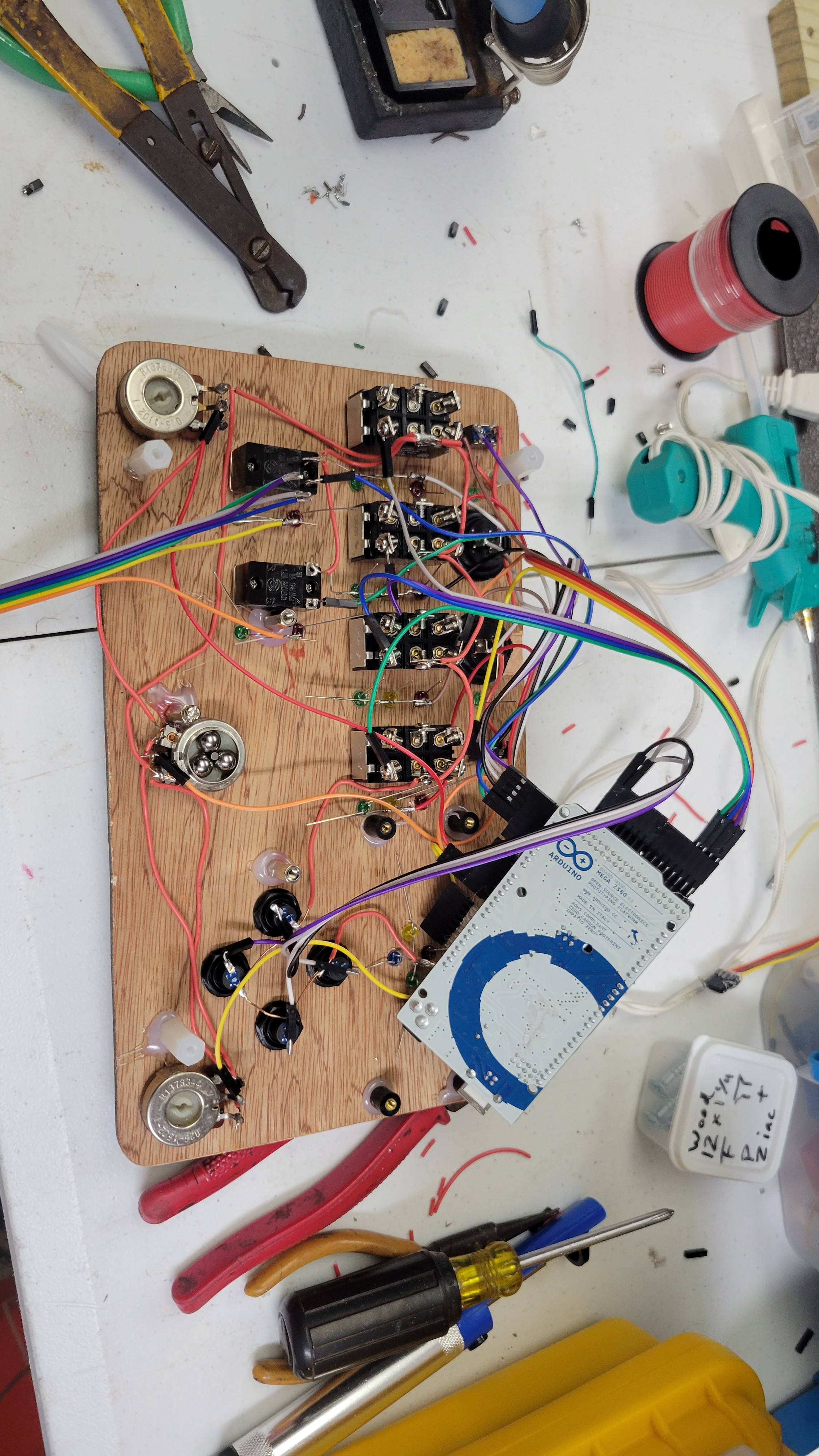
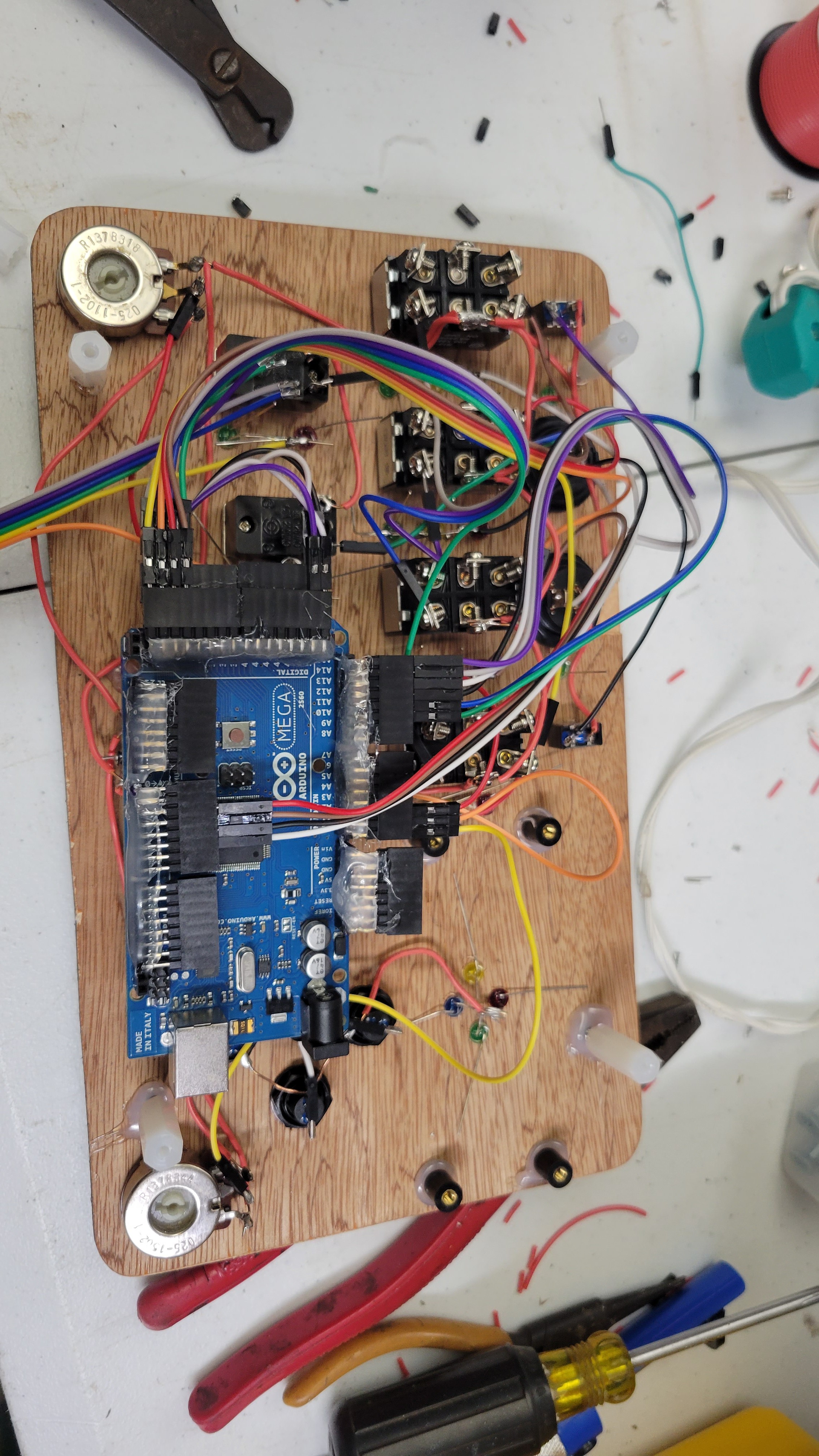
Point-to-Point wiring nightmare.

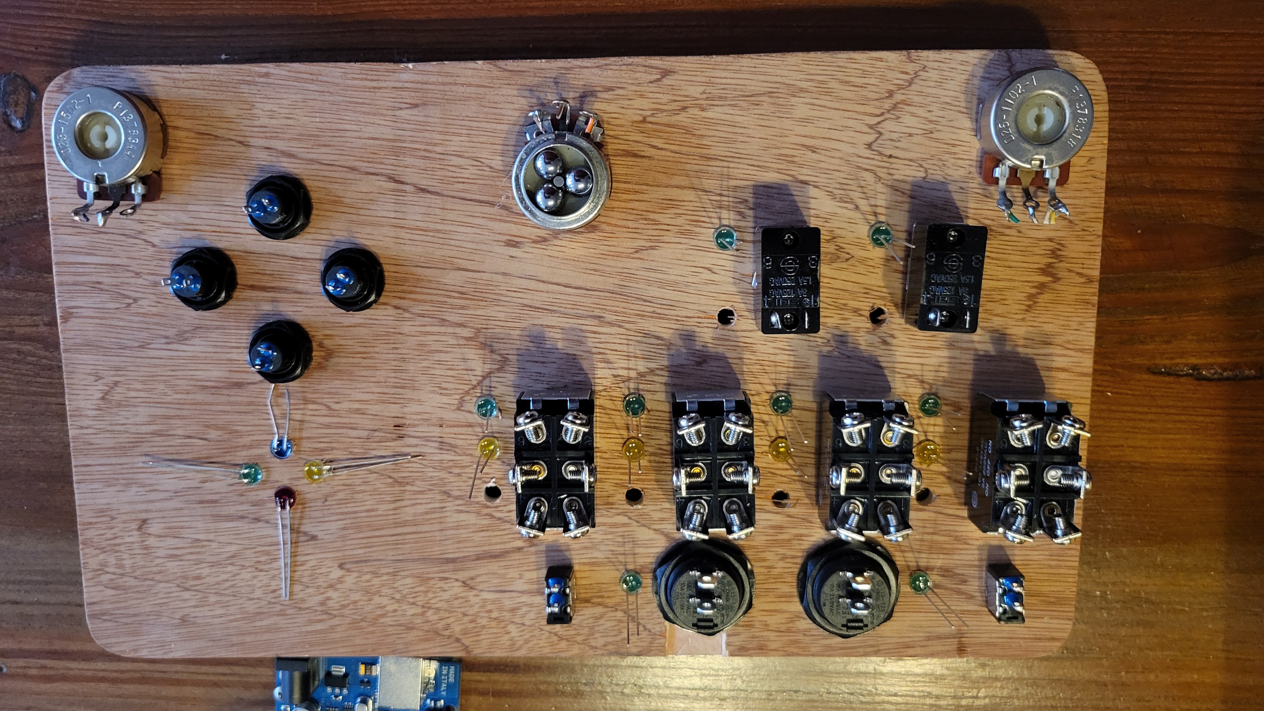
I designed the base portion to be highly flexible. Each switch has a dedicated input on the Mega, and I grouped the LEDs by switch. For the LEDs next to the switches, the Anodes are powered by an analog output for PWM control of the group, and the cathodes terminate to a Digital output through a current-limit resistor. This allows me to control dimming for each group of LEDs next to a switch as well as which LED is on, and I can turn on all or none. For the LEDs that are by themselves, they each use their own analog output (because I had plenty with the MEGA!) so I can dim them. 

Programming Basics

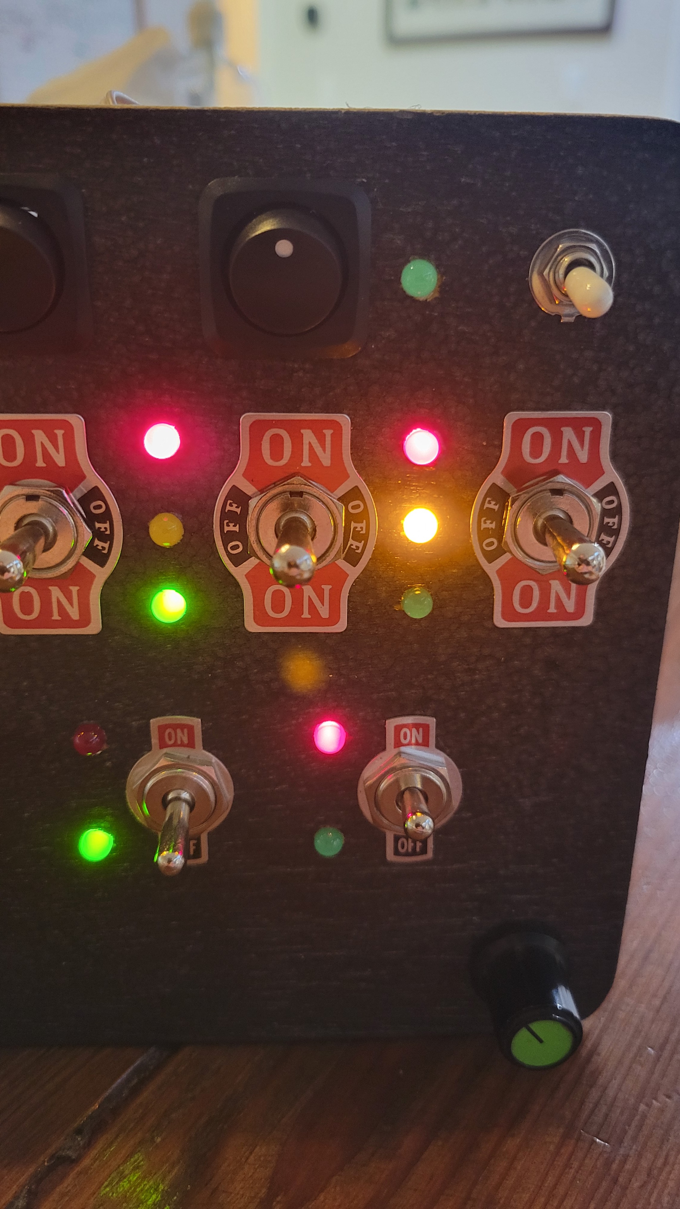
For the moment, Each LED simply displays the status of the switch next to it. This is to start by teaching simple cause-effect behavior. The "simon-says" buttons and LEDs simply light up for 1 second when the associated button is pressed. The potentiometers dim arbitrary sections of LEDs, and I have a floor at 10% so they don't turn off with the pots. Despite my desire to add more features, I made sure it just worked with the basic program. 

I utilized ChatGPT to write the majority of the code, as well as help troubleshoot when I had issues. You can find my conversation with ChatGPT HERE.

I created the schematic and simulated the code on wokwi.com prior to loading it on the arduino in the real world. You can access the simulation HERE. You can also copy it and modify it for your specific needs and switch configurations. I think this is much more useful than me posting my final code, as I have several pin assignment changes due to accidental wiring issues (fix it in software they say...). 
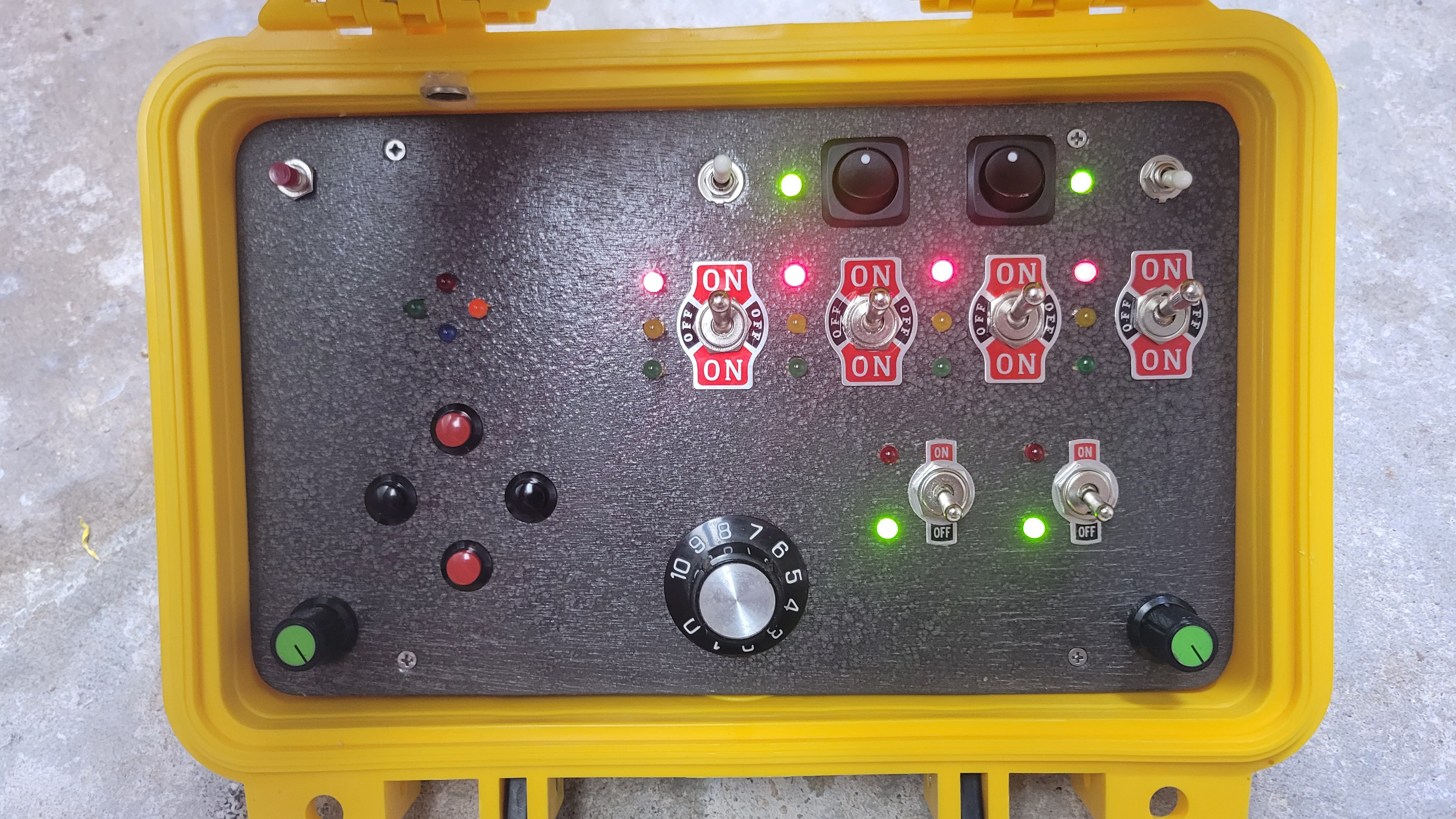
User interface
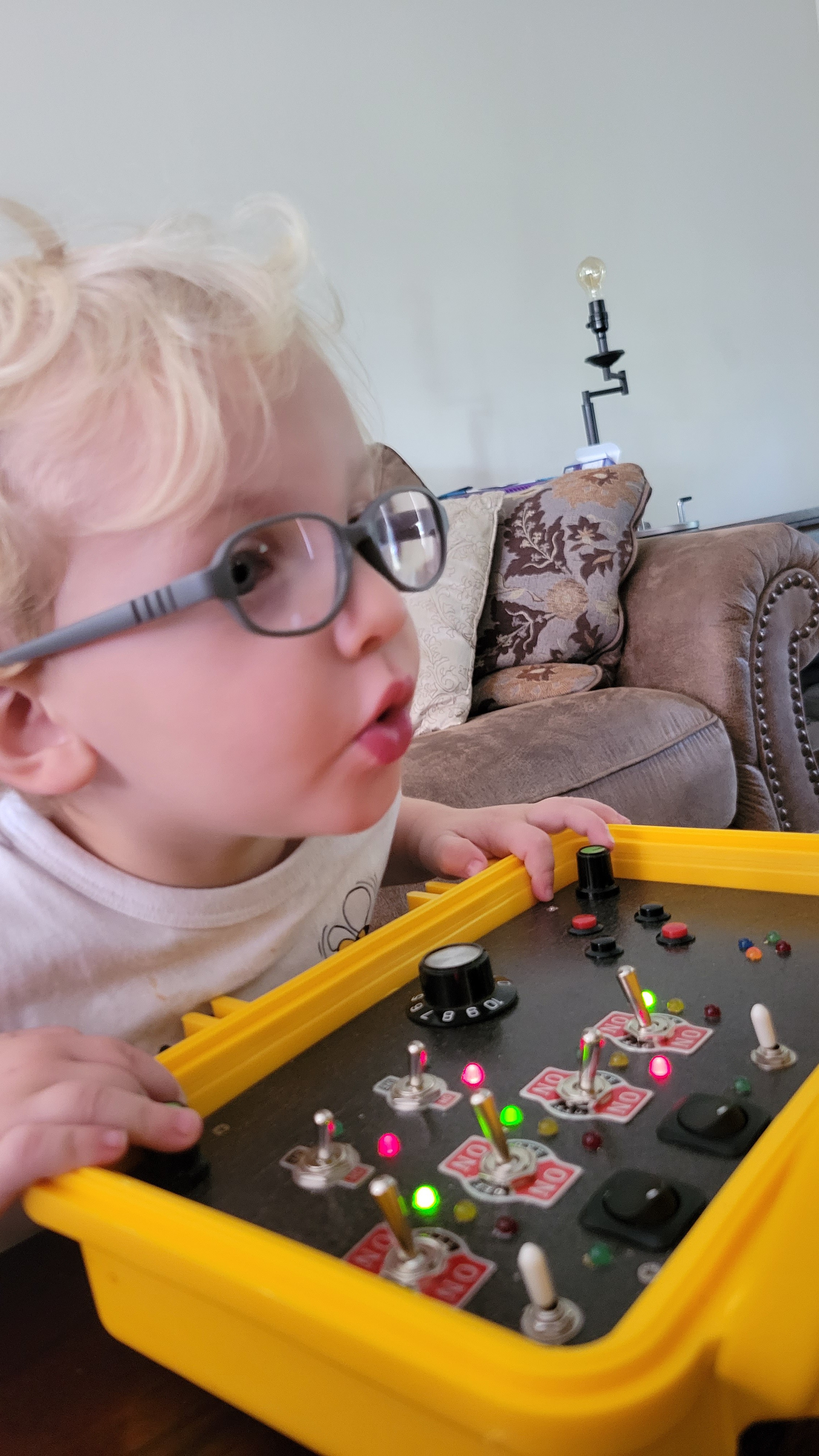
It turned out better than I hoped.

Future Upgrades

When I designed the switch layout, I had it in mind to create some simple logic puzzles for the next version. Here are my list of updates for V2 of the software, when I make it:

  1. White toggle switches will activate different modes. Top right will activate puzzle mode (up) or blinky mode (down) on the switches; top left will activate the simon-says game.
  2. Switch puzzle game: The LEDs by the switches will all turn off except for the top left switch. An LED next to that switch will flash until the switch is set to match. Each time a switch is set to the same position as the flashing LED, the next switch will activate, leading through all 6 switches. 
  3. Blinky mode: Instead of the POTs controlling random dimming, I'm going to change the LEDs to blink/pulse. The middle pot will control...
Read more »

Toddler_Cyberdeck_v2.ino

Adds low power and auto-power off. Requires the Low-Power library by Rocket Scream Electronics

ino - 15.72 kB - 08/19/2024 at 00:05

Download

Switch layout options.pptx

I used powerpoint to plan the switch layout. Faster than a CAD system since accuracy was not required.

presentation - 75.65 kB - 08/15/2023 at 04:03

Download

Toddler_Cyberdeck_v1.ino

This is the final V1 code, as loaded into the project. This has some specific changes to fix hardware errors, so you should use the wokwi.com project as the basis for your own.

ino - 10.88 kB - 08/15/2023 at 03:45

Download

  • 1 × Waterproof case IP 67 Hard case 11.65 ”x8.35”x3.78”(Yellow)
  • 1 × Arduino Mega
  • 4 × Large DP3T Lever Toggle Switch R12-8 is written on the side. Only using one side of each. Came from a Radio Shack switch assortment pack.
  • 2 × Med SPST Lever Toggle Switch SGI, no part number. Came from a Radio Shack switch assortment pack.
  • 2 × Small SPST Lever Toggle Switch "55" on side. Came from a Radio Shack switch assortment pack.

View all 23 components

  • Implementing power saving

    Josh08/19/2024 at 00:03 0 comments

    One of the issues with the v0.1 code was that the LEDs never shut off. Even thought the 18650s are pretty high capacity, they would die in a few days. The power supply will turn off if the power draw is below a threshold for a time delay, so I'm going to take advantage of this and the fact that I don't have a means of directly controlling the power supply from the arduino by putting the arduino into a low power state after a period of inactivity.

    I added 3 different features:

    • Auto dimming - Dim all the LEDs to a low brightness after a time delay of inactivity
    • Auto off - turn off all LEDs and place the MEGA in a low power mode
    • Interrupts - if a switch is flipped between the time the MEGA enters low power mode and the power supply shuts itself off, the MEGA will wake up.

    The auto dimming doesn't work very well, probably because I don't have a good dim level set, but maybe I'm also not handling it right in the code. I don't really care for the moment because it shuts off and I'll save time between charging. I'll leave the dimming issue for "future me".

    Code V0.2 can be found on the simulator at WOKWI.com:

    https://wokwi.com/projects/370628580593956865

  • Final Countdown

    Josh08/15/2023 at 03:51 0 comments

    Yesterday I finished the build, with mounting standoffs drilled through the case. I also mounted the magnet for the LCD activation into the base using some woodworking tools to recess it to prevent it from being pried off. You can see the Sensor glued on to the lid on the left, and to the right of the sensor I have hot-glued the USB connector for the screen so I can charge it and load new videos.

    Here are the pictures of the final project!

    Also some of my son trying it out for the first time!

  • Software! By ChatGPT!

    Josh08/13/2023 at 18:49 1 comment

    Once I finish the wiring, it was time to load the code that I had written using ChatGPT and simulated on wokwi.com.  After realizing I didn't have the proper drivers installed, I loaded the code and proceeded to find something wrong.... Actually only five things wrong:

    1. Two of the 3-way switches had more than one LED illuminated.
    2. Two of the 3-way switches activated LEDs next to a different switch.
    3. One of the toggle switches had LEDs illuminated inverse of the other.
    4. The working 3-way switches had LEDs illuminating inverse to the switch.
    5. On the switches with more than one LED illuminated, turning the potentiometer for dimming made one LED brighter and the other dimmer.

    Solutions:

    1. Turns out I accidentally reversed two red LEDs when I installed them. Resoldered to fix.
    2. This one was one of my switch connectors being reversed. The top of all the switches go to a single four-pin connector, same with the bottom. One of these connectors was backwards.
    3. This one was more complicated because when I super glued the pin connectors together to make a single connector I accidentally cross the wires for 2 LEDs. This one I fixed by swapping their pin assignments in code.
    4. Similar to solution (2), but I had each connector plugged into the wrong set of pins. The code thought the switches were up instead of down, and vice versa.
    5. This is the same as solution (1) but worth mentioning separate because I was using the digital outputs as high for off, but since the LED was backwards it was conducting back into the analog output when the PWM signal was LOW. Since the time period for low and high on PWM are inverted, when I dimmed the properly connected LED, the improperly connected LED got brighter accordingly. Cool effect but not what I was looking for...

    Amazingly, after fixing all of these things which were hardware issues, the code worked exactly as I designed it! The only thing I did to the code was add some serial output in order to troubleshoot the issue with the reversed LED which actually took a little while to figure out.

    I will post the code separately.

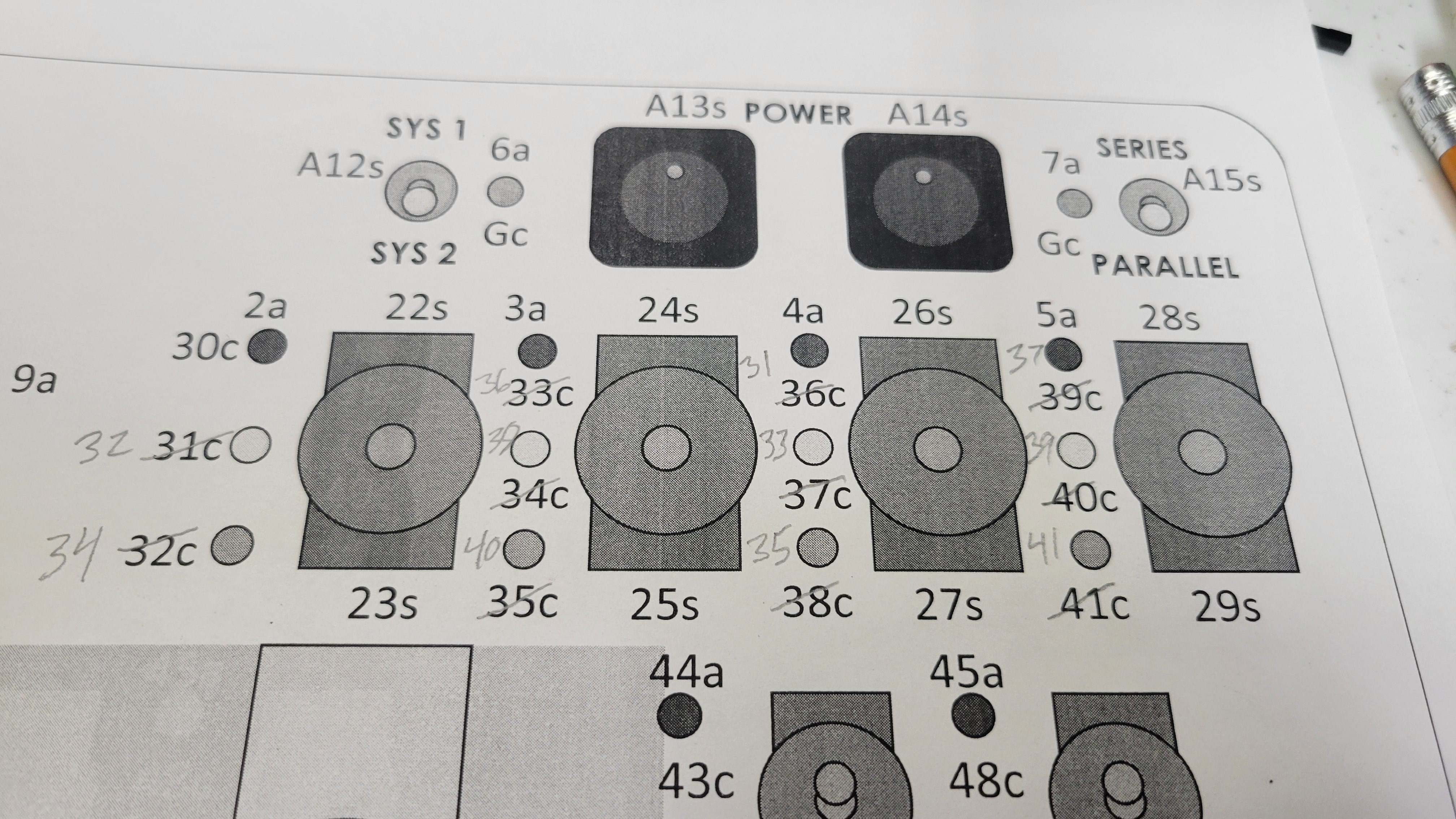
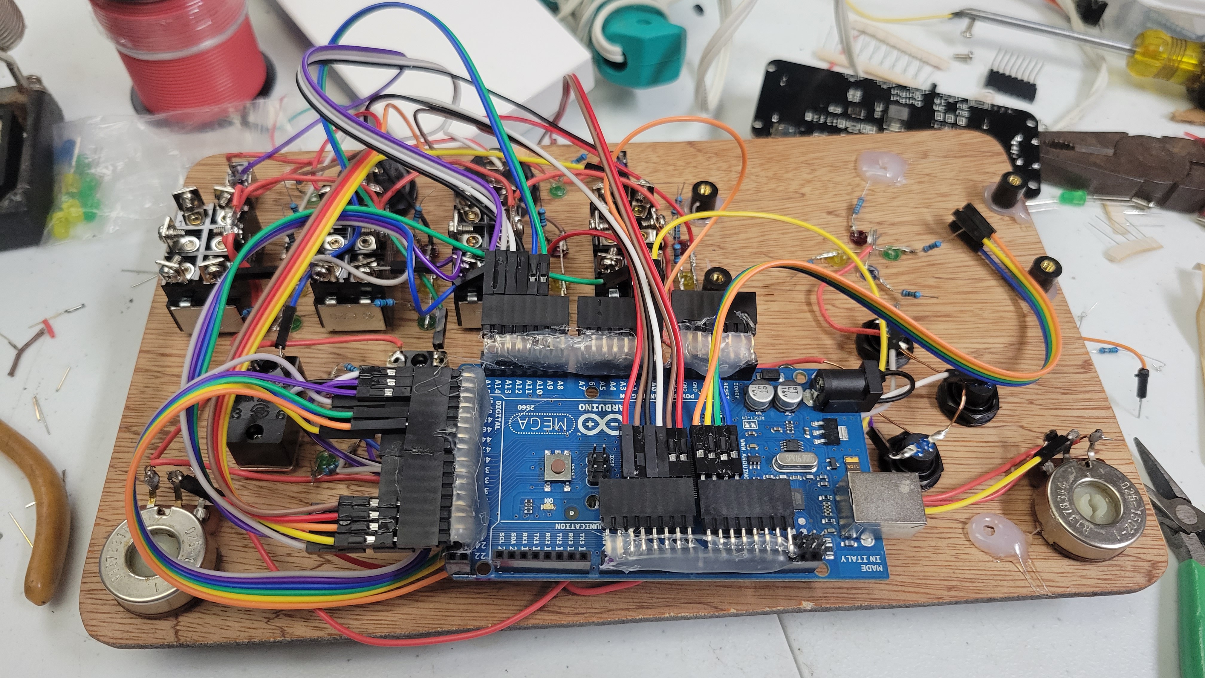
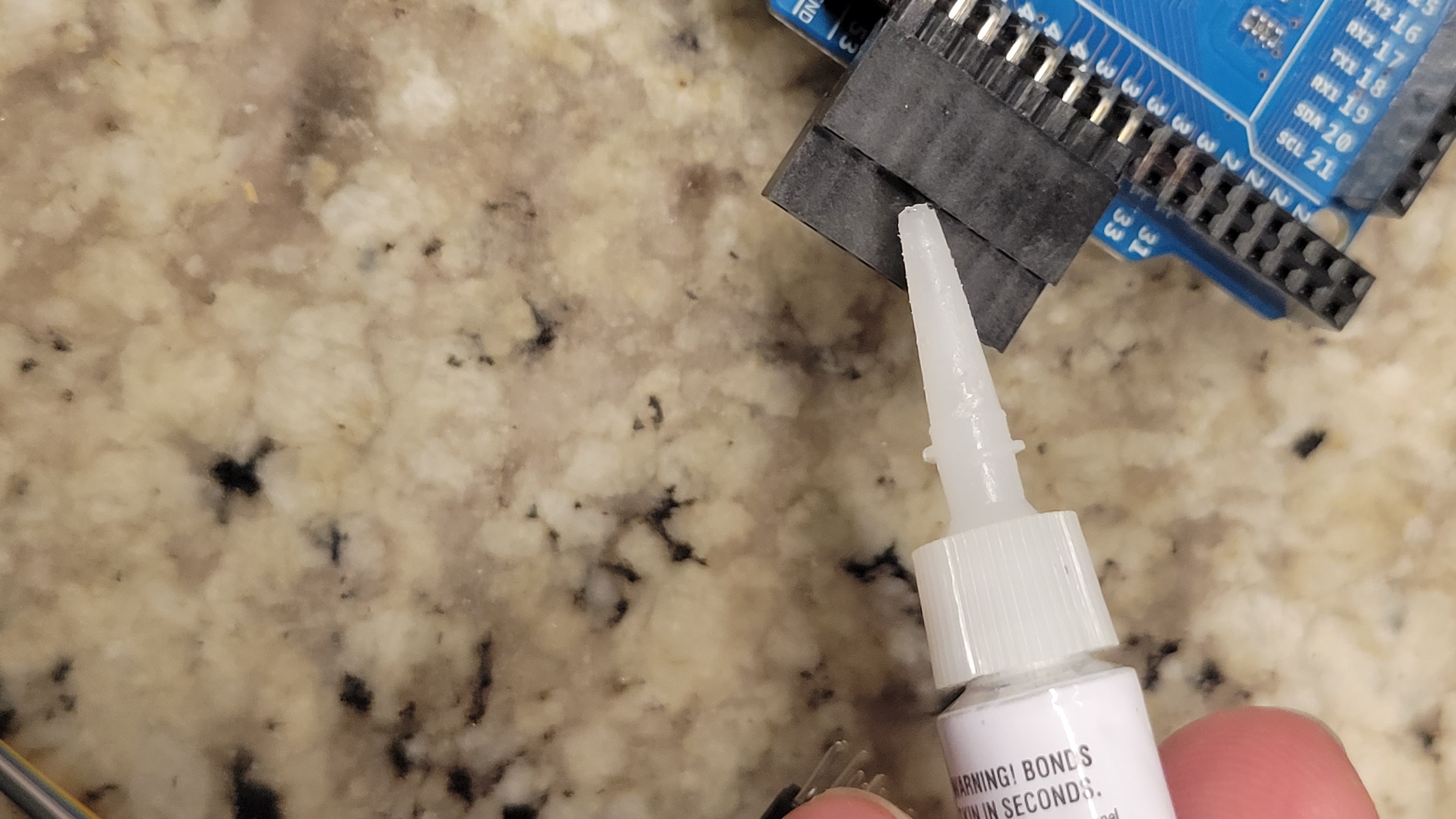
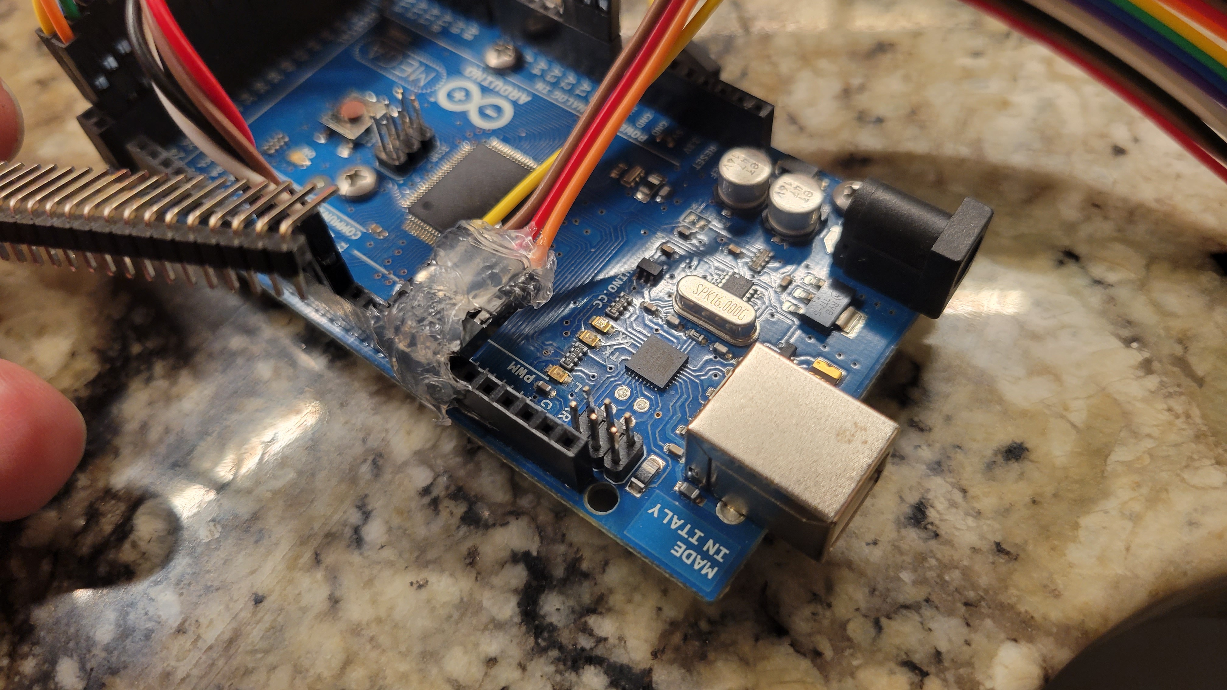
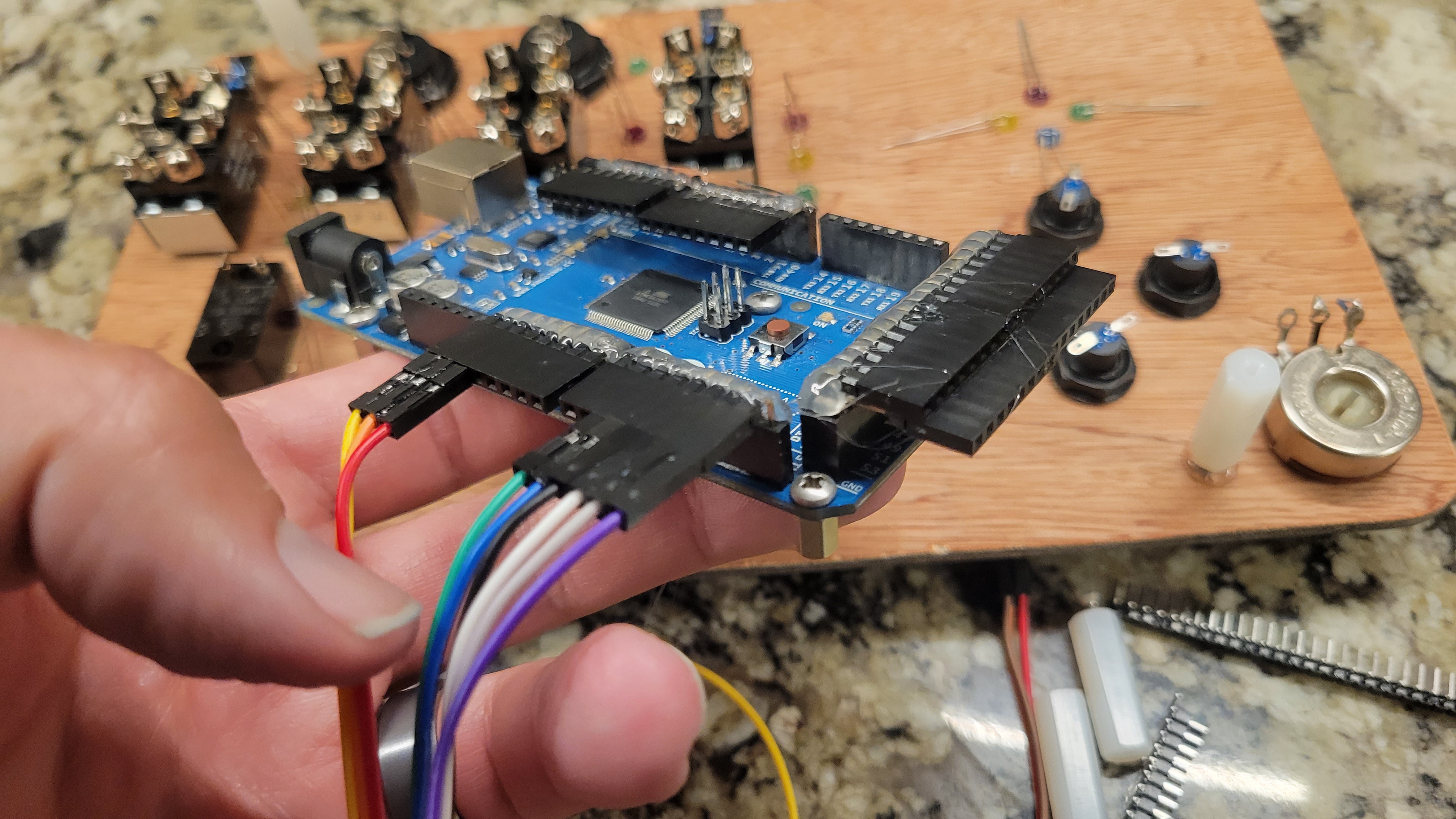
    While I was putting everything together, I had a diagram that I printed out with all of the pin destinations on to help me hook it up properly. When I determined I had the wrong pin locations, I manually updated this sheet. The biggest update was actually rearranging the first six three-way switch LEDs to be on even pins and the second six to be on odd pins. Just let me plug them in to the Arduino in groups of six on my 90° makeshift pinheaders. The ribbon cables come with individual pins but I used super glue to make them into multiple-pin connectors.

    Other items to note: I have been using ample amounts of hot glue in order to secure everything against the inevitable shocks and vibrations of a 2-year-old's playing.

    Here are some pictures:

  • Race to the finish!

    Josh08/13/2023 at 05:04 0 comments

    I've been busy and it has been difficult to find time to work on this, and even more difficult talking the time to log progress.

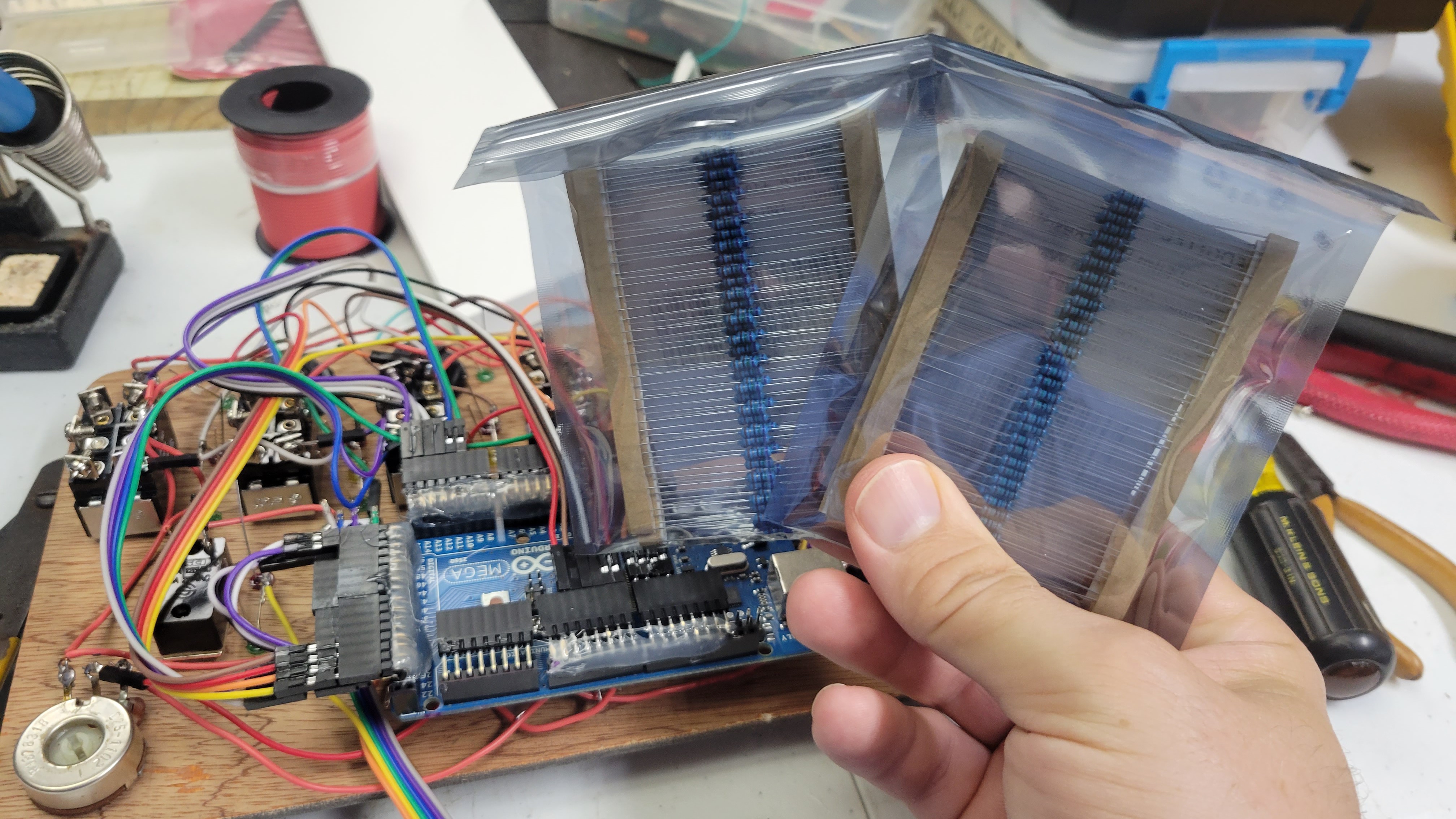
    The majority of work was all in the wiring. I got delayed a little when I realized I didn't have enough... or any... resistors properly sized for the LEDs.  After a few calculations I settled on 75ohm for the blue and green(I thought) LEDs and 150 ohm for the red and yellow. (Hindsight as I'm writing this... I could have checked the forward voltage of the LEDs with my cheap multimeter which has a diode test function... Oh well). I ordered some online and got them a few days later.

    After trying both of the resistors on each LED, I ended up using the 150ohm on all but the one blue led. 

    I had a difficult time deciding how to handle the power supply I bought. Unfortunately it has a push button switch to make it turn on with one press and off with two presses. I wanted to use a micro switch to turn it on when open and off when shut but that is not compatible with the power supply. So I simply added one more switch to the board for power, directly solder to the power supply.

    Another odd thing about this power supply is that it will shut itself off if there is low current for something like 30 sec. This will actually let me add a timeout code to the Arduino to shut off all the LEDs after a few minutes of inactivity. Hopefully that will drop the current draw below the threshold and it will shut off. Then it won't be drawing power when my son puts it down. 

    Shots below. (Again, not in any reasonable order)

  • Medusa...

    Josh07/30/2023 at 22:14 0 comments

    Never underestimate how long it takes to solder wires! 

    A few more pictures of the progress...

    This is about the time when I determined that I didn't have enough, or actually any properly sized resistors for the LEDs to run on 5 volts. Time to get some from Amazon!


  • Missed Deadlines... New Deadlines.

    Josh07/27/2023 at 14:27 0 comments

    The schedule always slips to the right... 

    The birthday party came and went and I still have a ton of wires to solder and install. In order to help, took the powerpoint file that I used for laying out the switches and added labels above, below, and beside all of the switches. The labels are the arduino mega pin corresponding to the switch or LED connection. This way I can just have a piece of paper next to the board on desk while I'm soldering and don't have to frequently look up and trace the wires in the schematic.

    New deadline is the end of the Cyberdeck Challenge. My wife pointed out that our son won't know the difference anyway. He also got a much wider range of V-Tech toys on his birthday than we had expected, so he already has a bunch of buttons and lights to distract him. When I finish this, it'll at least not have to compete for his attention with a bunch of other stuff at the same time!

  • Space: The Final Frontier

    Josh07/20/2023 at 04:07 1 comment

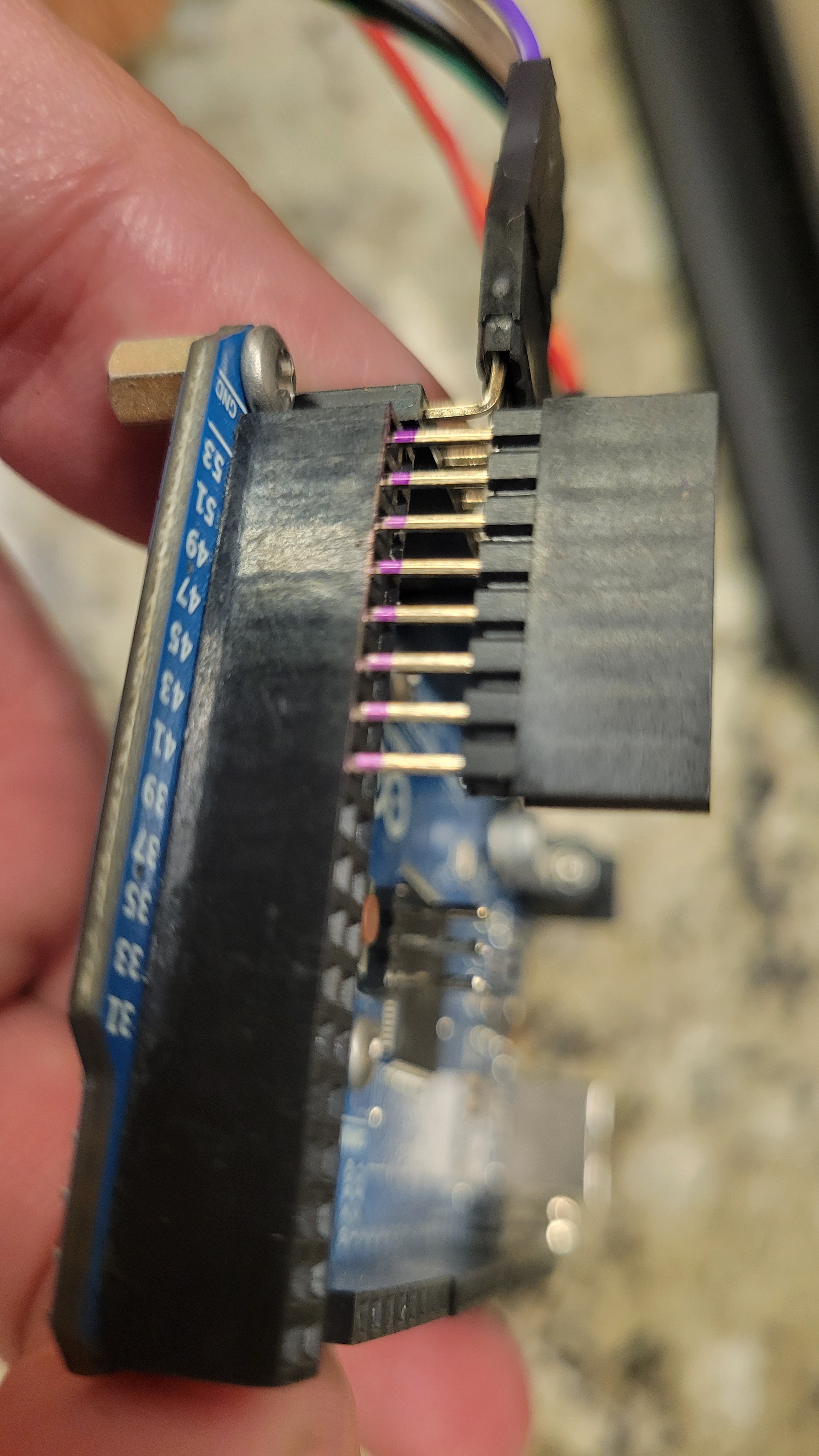
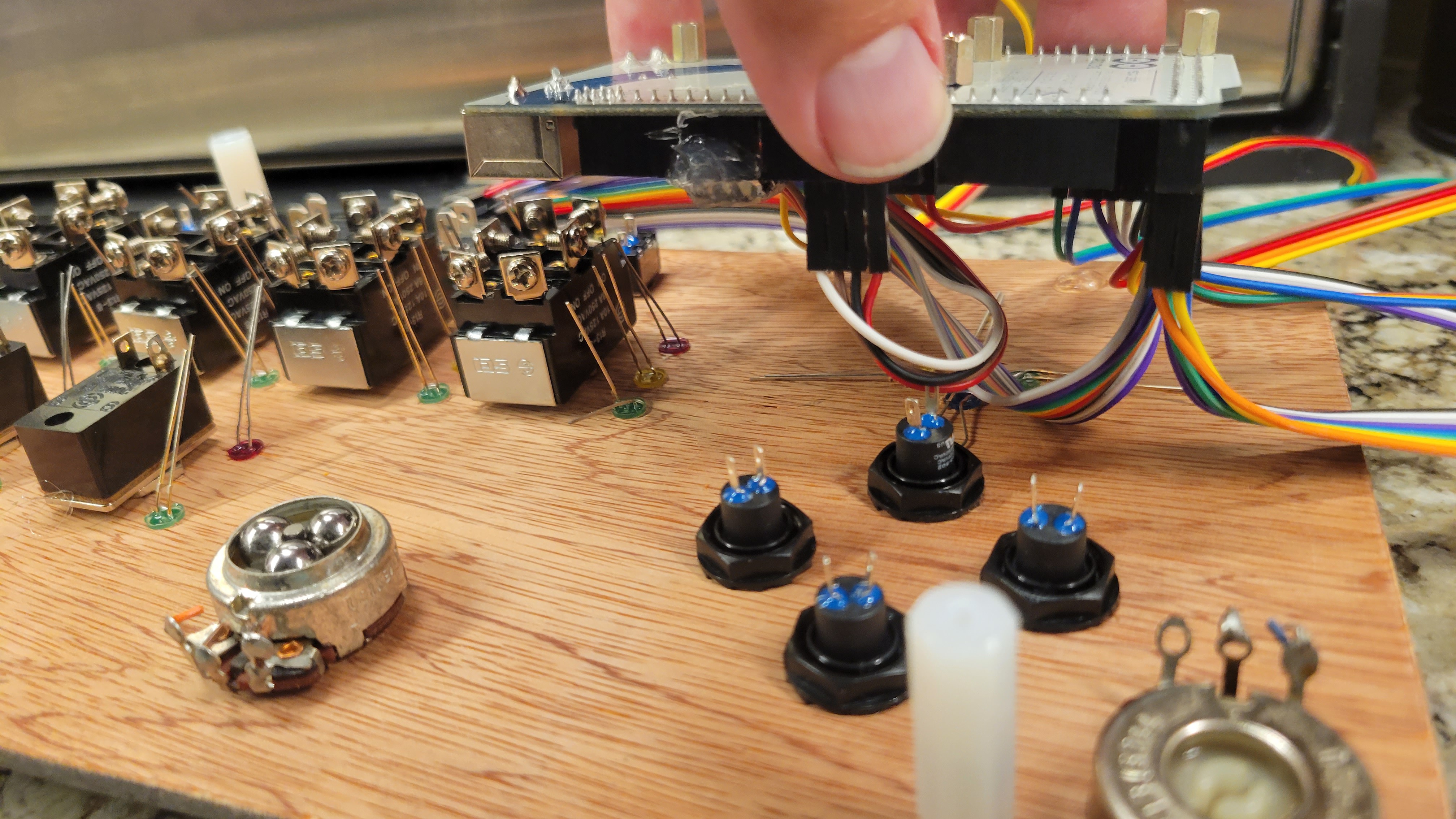
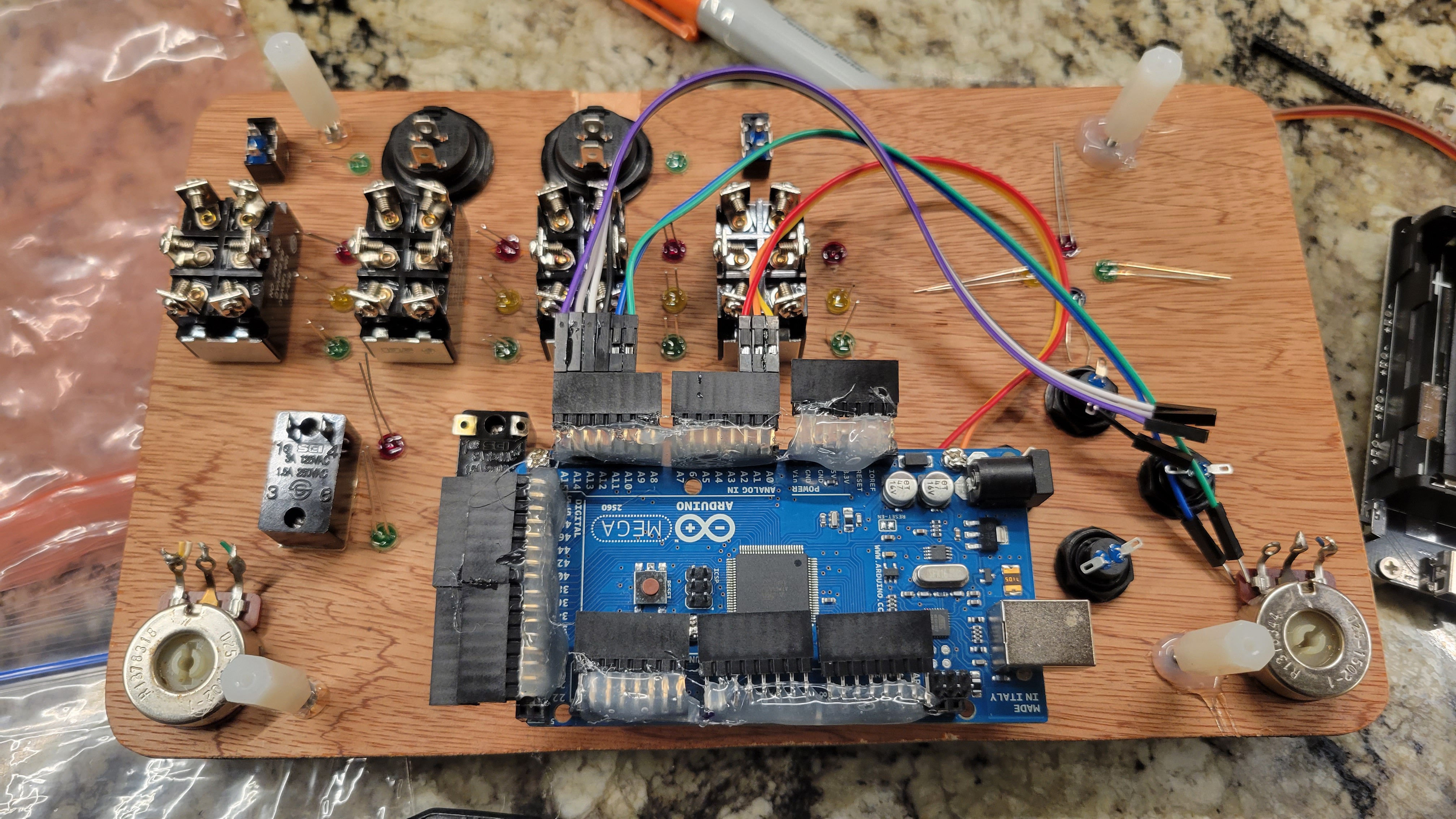
    Yeah, I totally didn't have enough space for the wires to plug in to the pin headers and still have the Arduino fit below the switchboard and not interfere with any switches, as well as have room for the battery mount. I thought I had room but I was totally wrong.

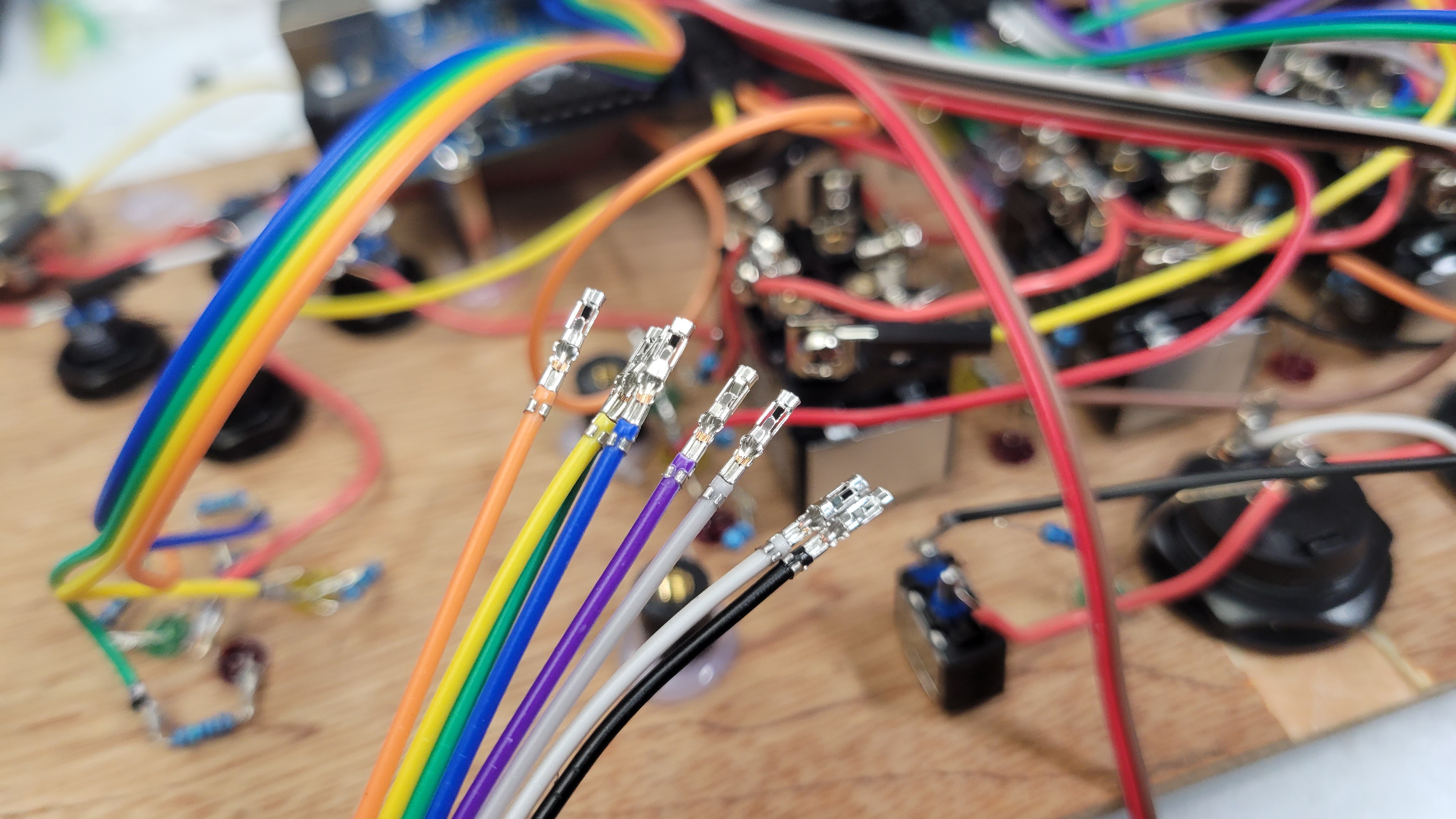
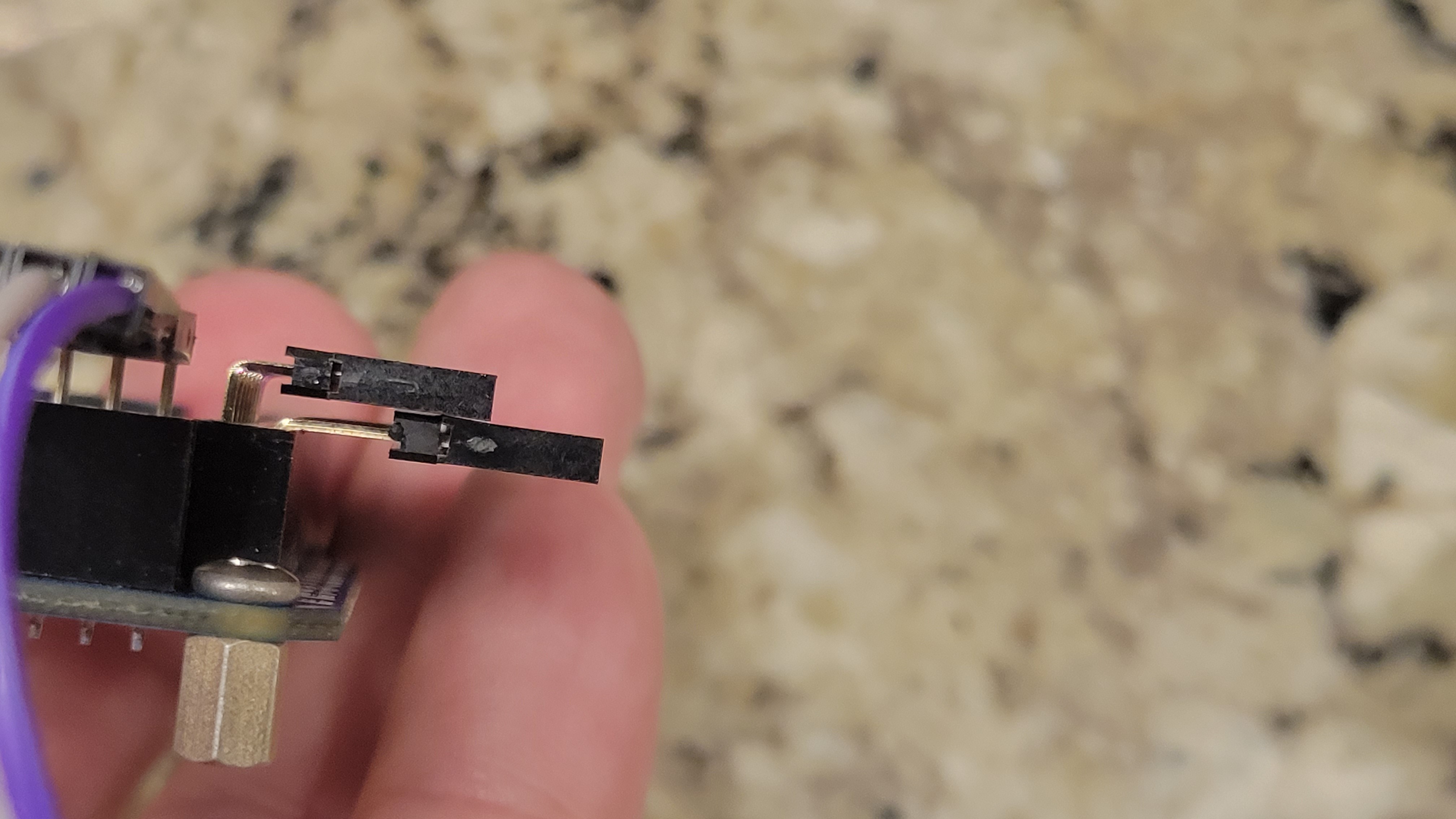
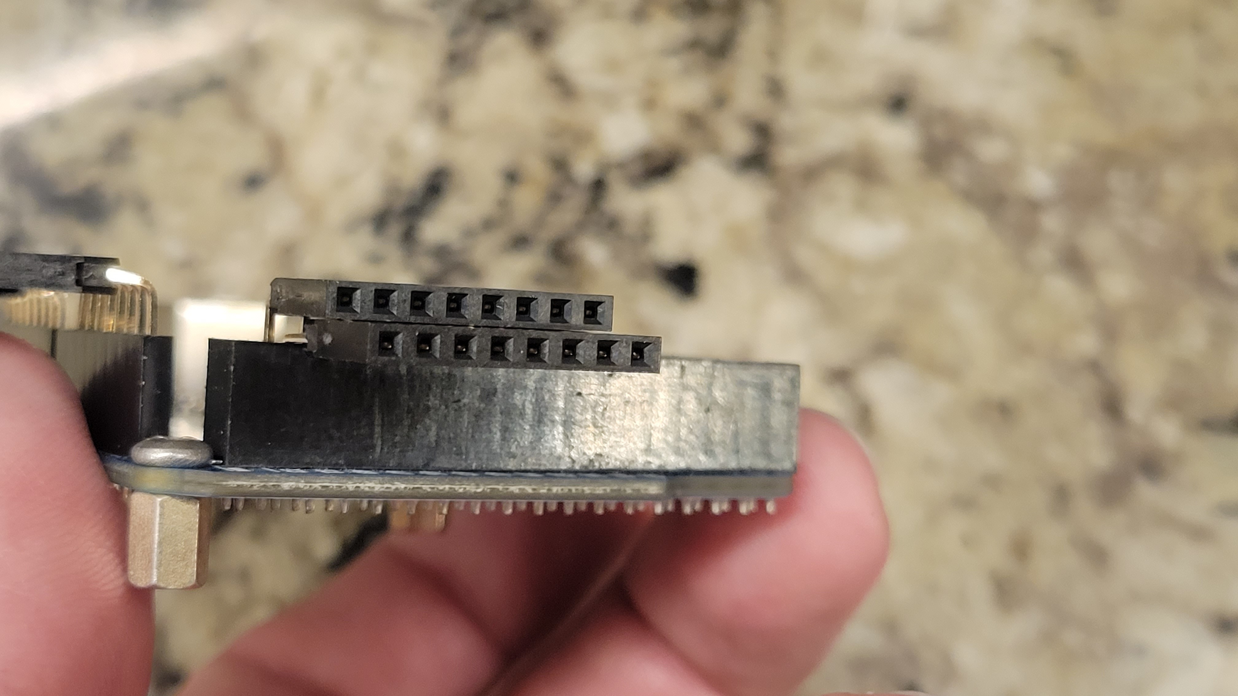
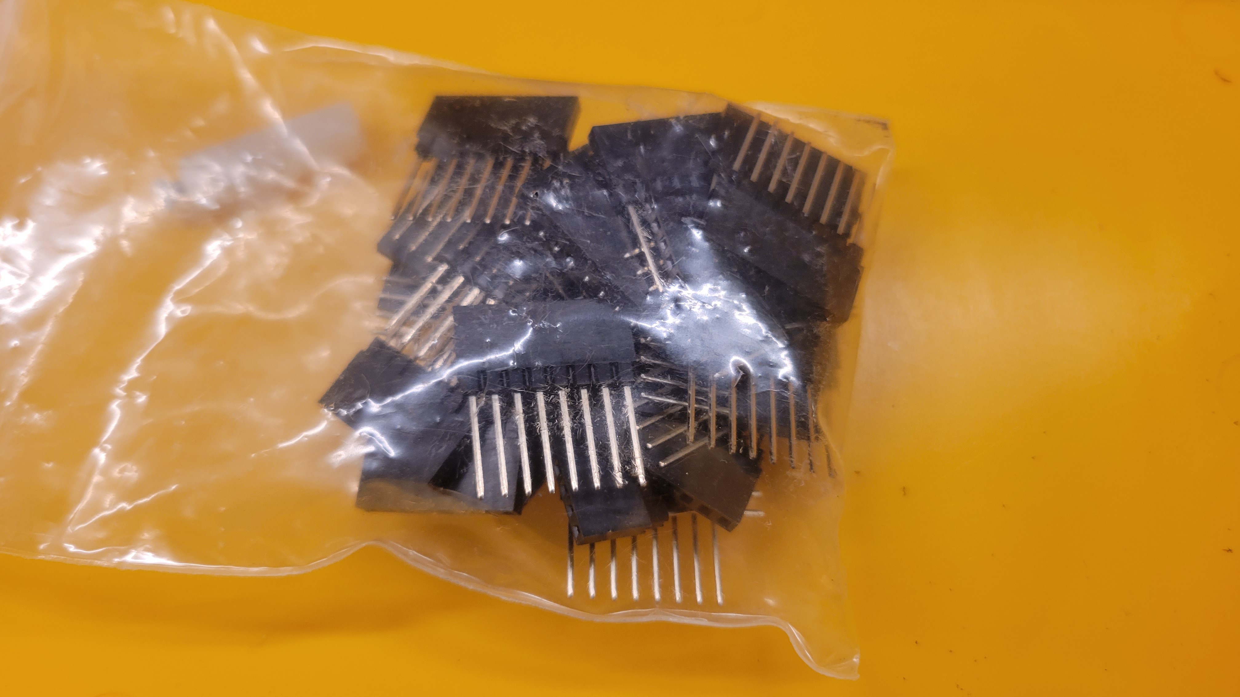
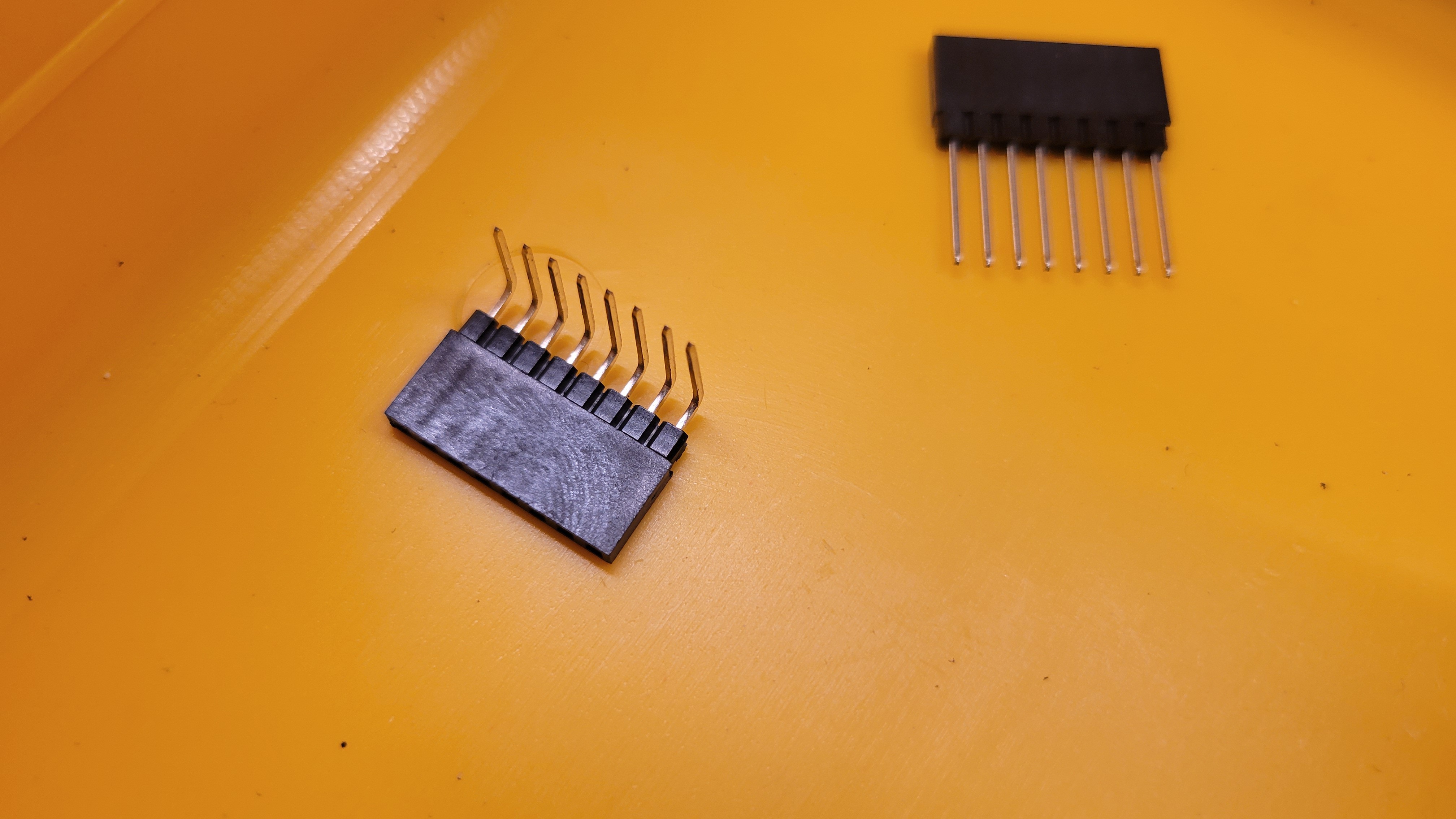
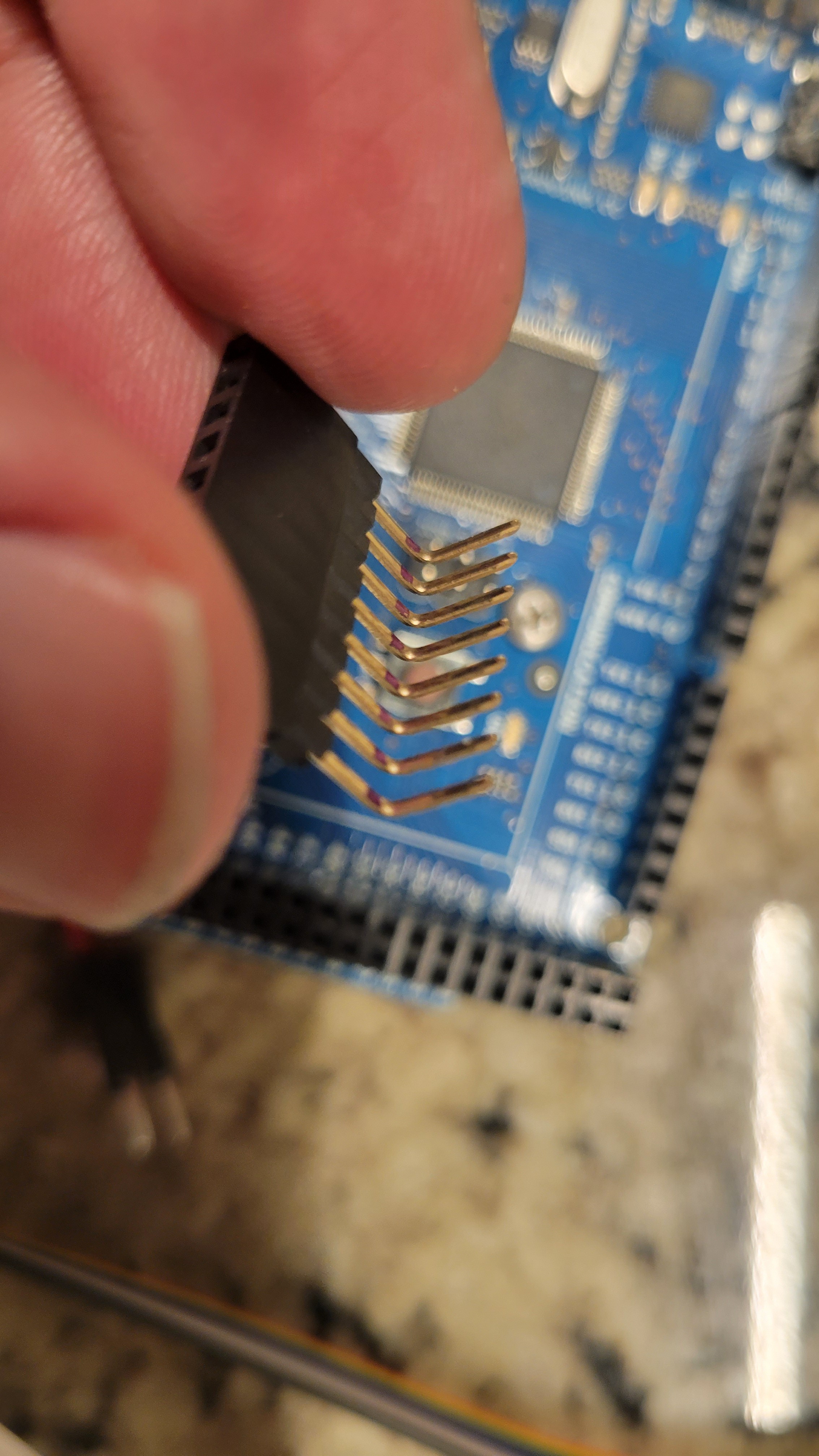
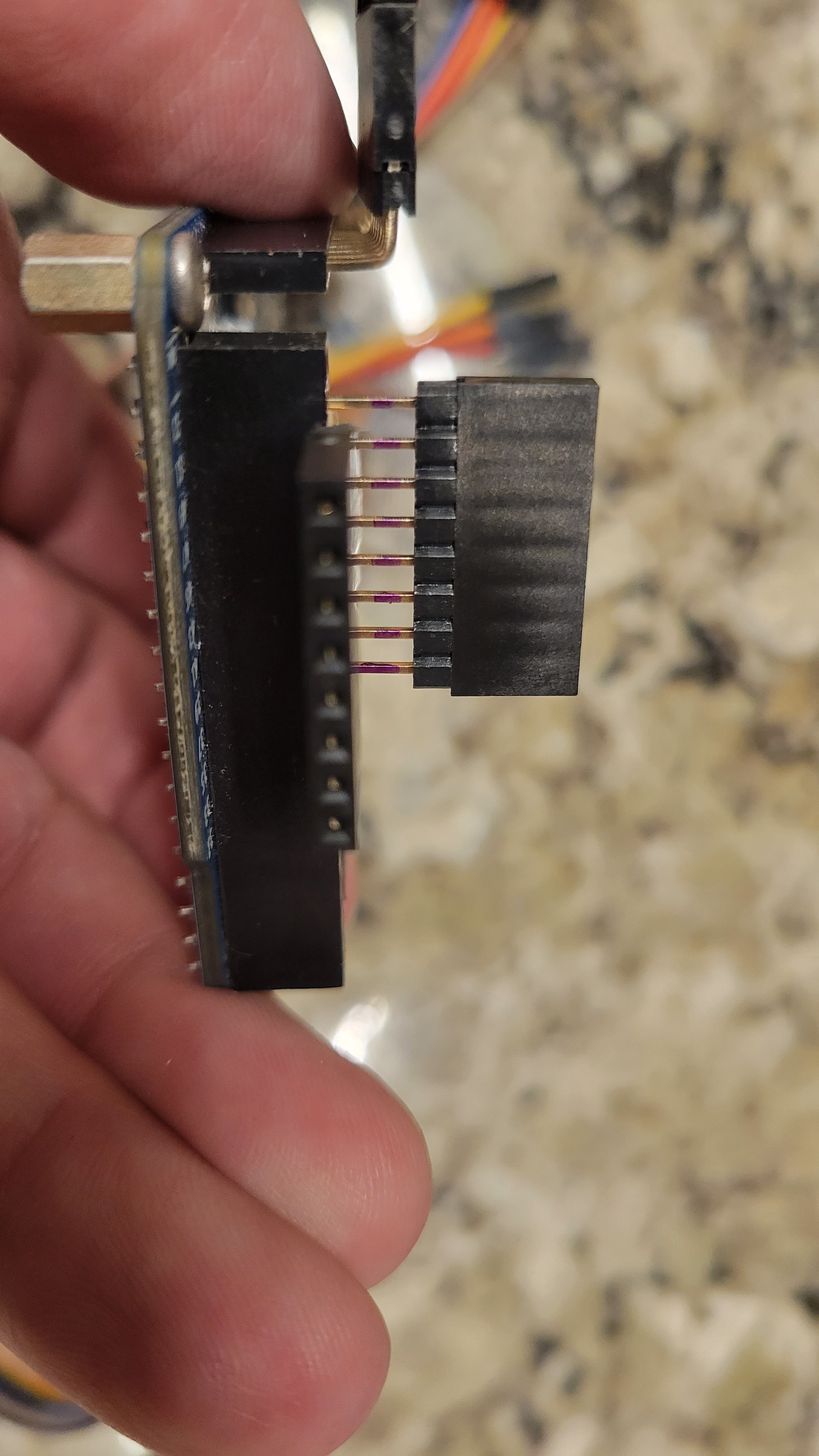
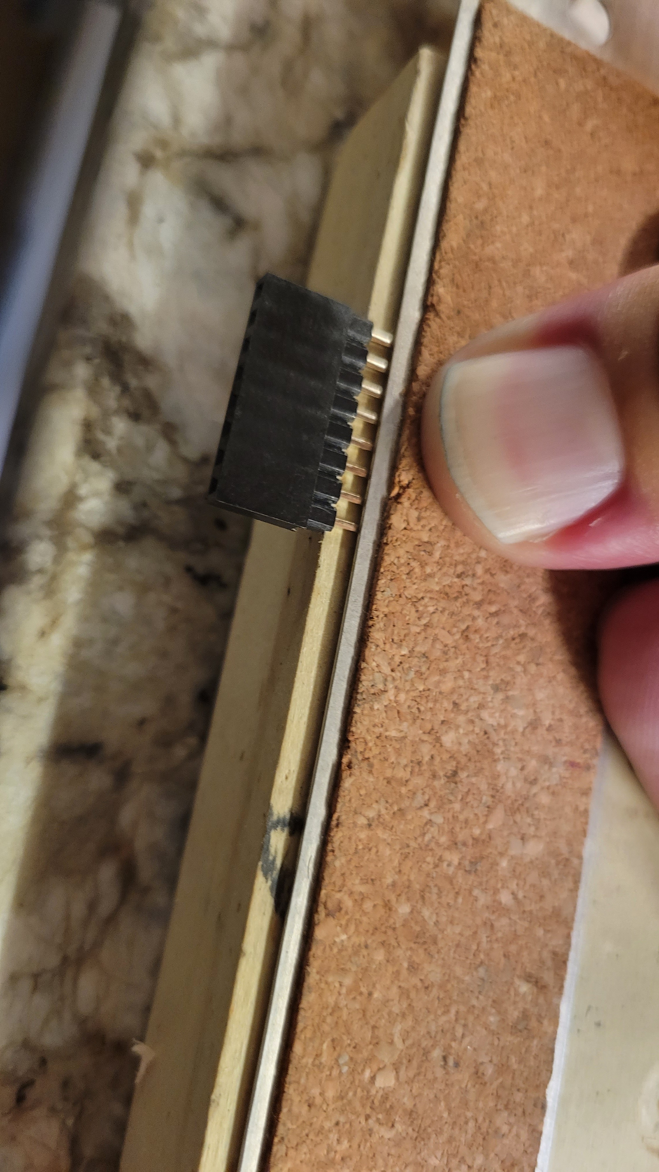
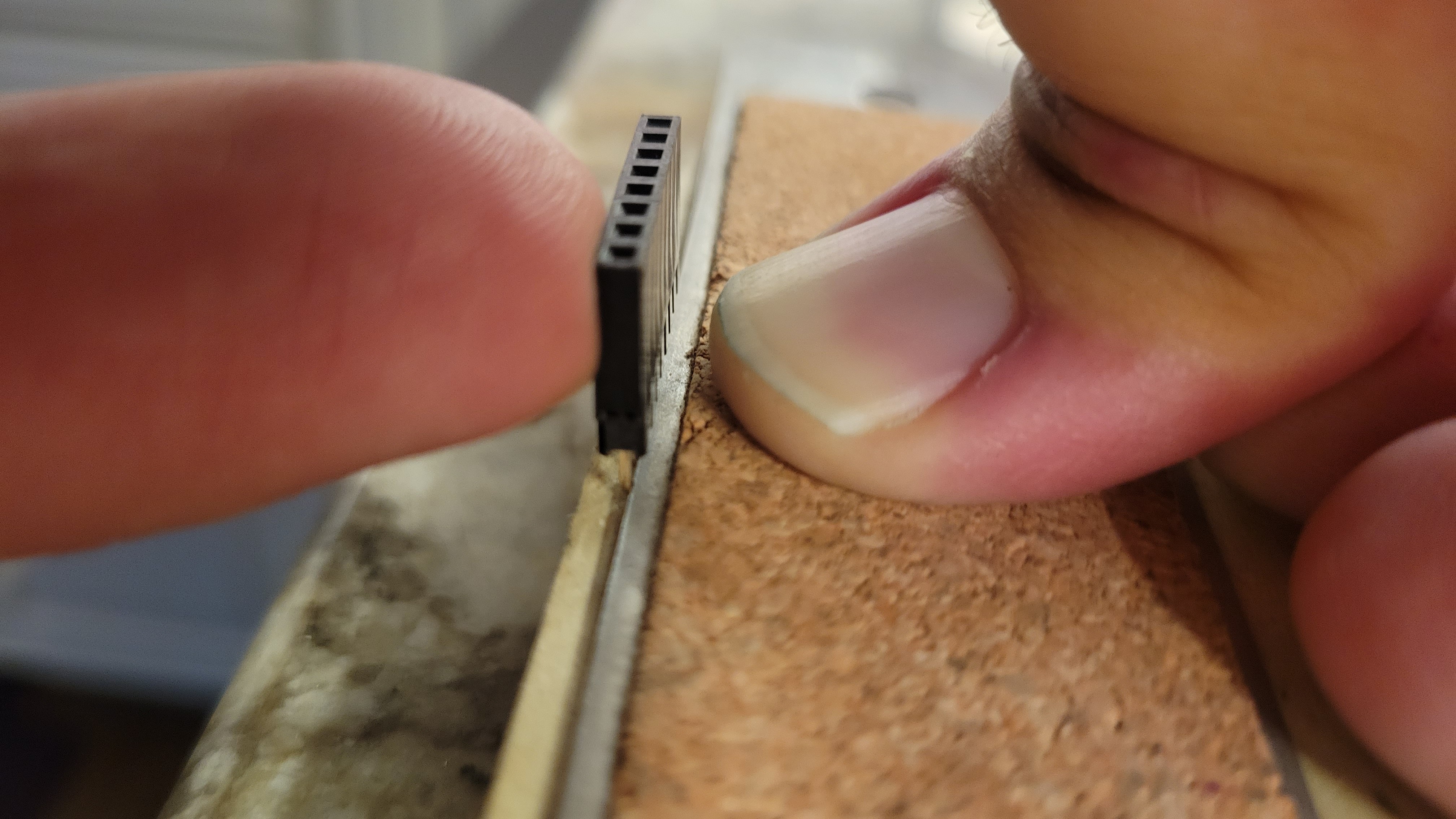
    I scrambled to find a solution to make 90° connectors for the pin headers. My first solution idea was to take 90° pin headers and glue them into the sockets on the ribbon cables, which I would have to recut because I use the ribbon cables with pins first. It was going to be tedious and I wasn't really liking the way it was turning out. Then I remembered I had straight, extended length pin and socket headers made for stacking CCAs. I was able to mark these with a sharpie and then bend the pins 90° and create my own 90° adapters to use the same cables I made up a few days ago. 

    Once I made all of the 90° adapters and plugged them in, I had plenty of room to fit it underneath the switch board. I also added lots of hot glue to hold it all together. 

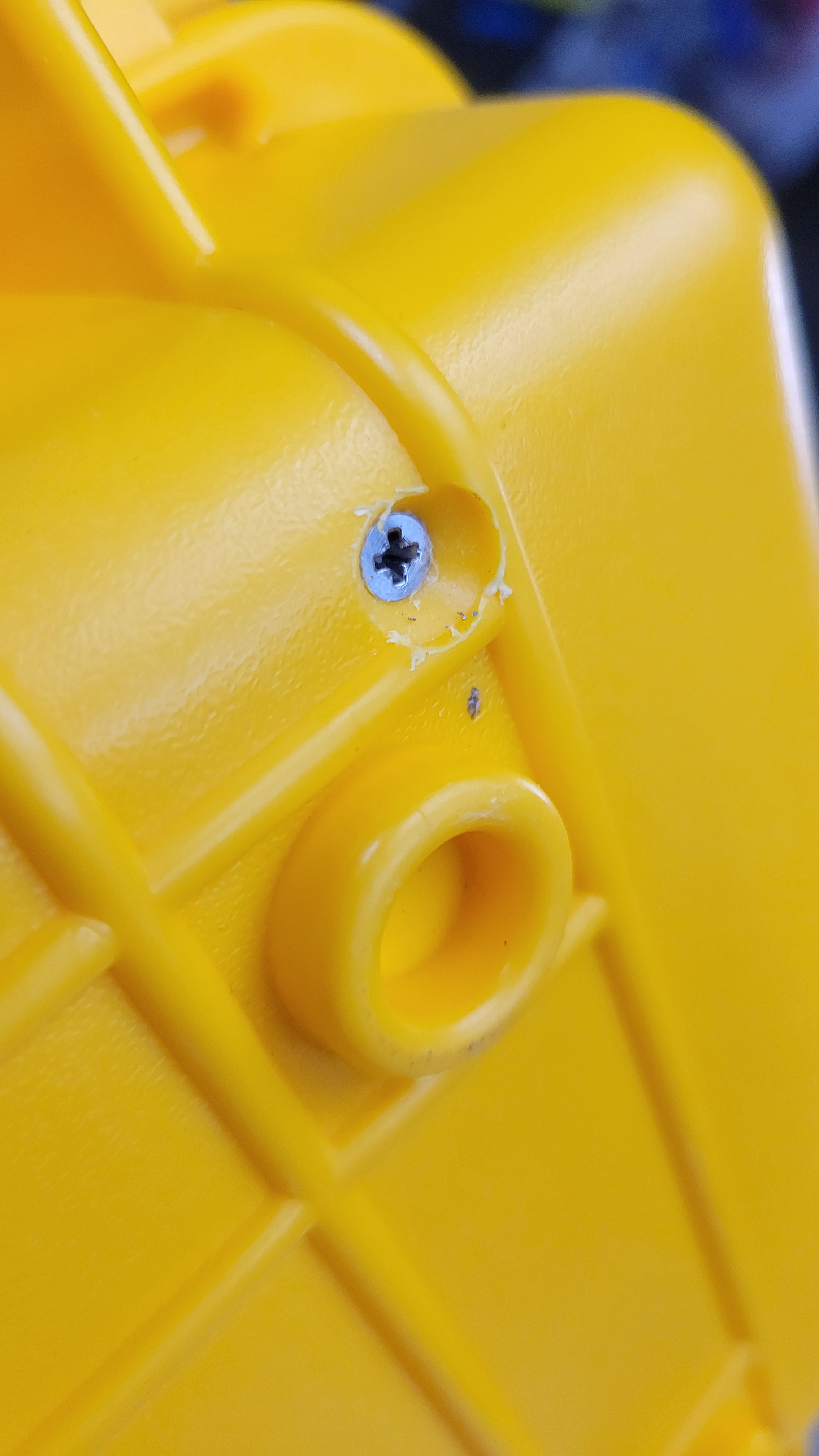
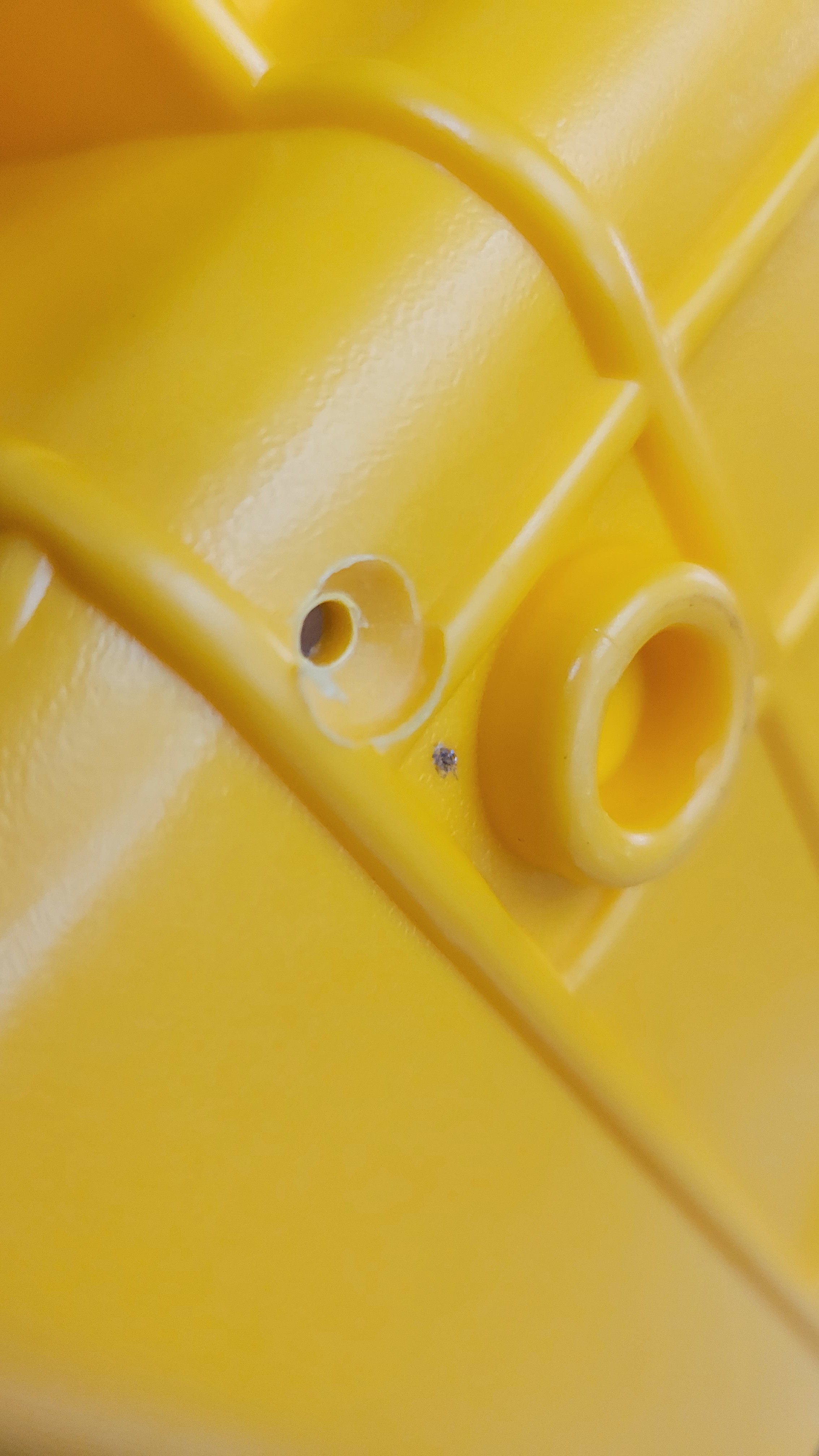
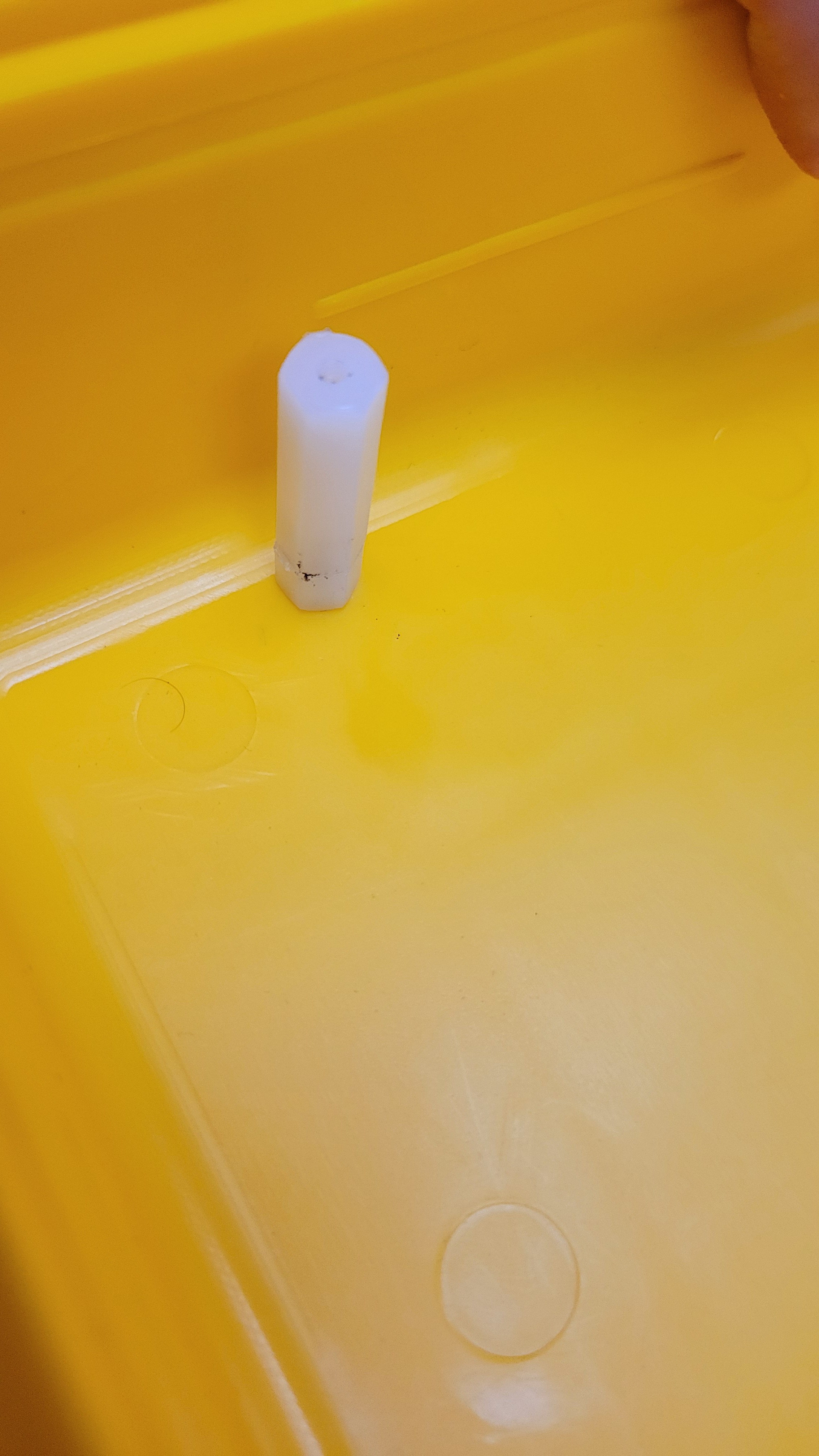
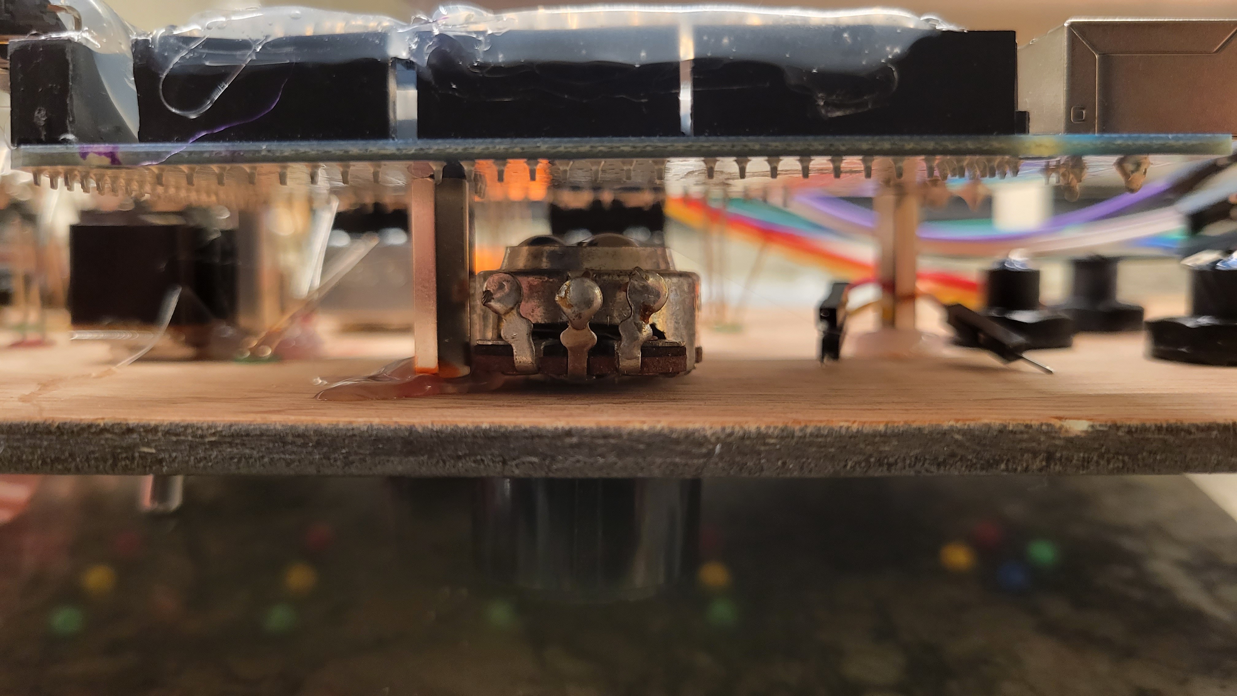
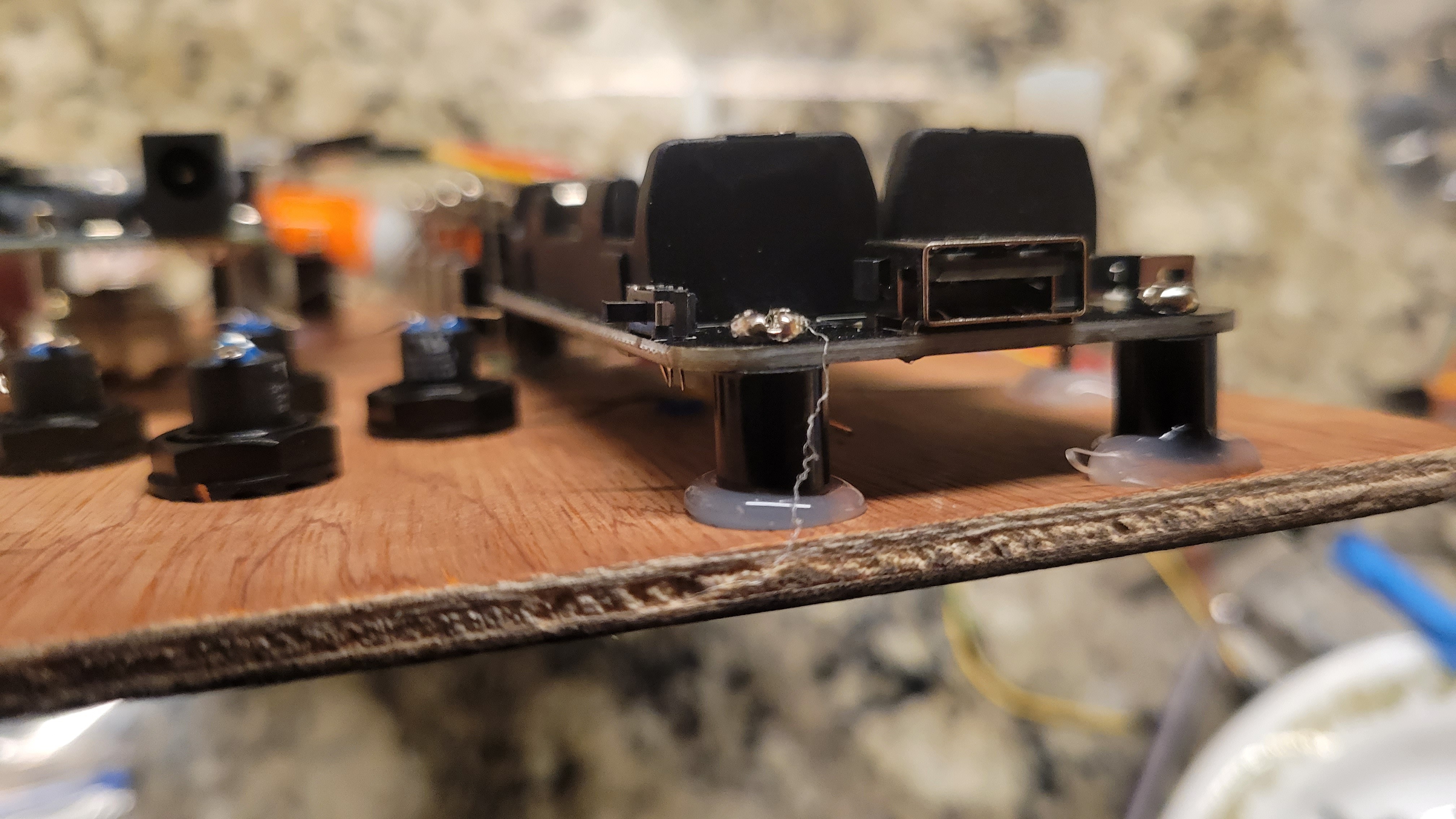
    To figure out the standoff length, I hot glued screws onto the back of the board and threaded the standoffs on to the screws. I then unscrewed the standoffs to adjust their length. 

    I adjusted them down enough to fit the Arduino under the center potentiometer and I had standoffs just the right length so I hot glued them on as well. I also hot glued on standoffs for the battery holder and everything fits well inside the box now!

    Here are some pictures from tonight's fun! The upload order sometimes scrambles and I don't have time to re-sort the images, so wysiwyg. 

  • LEDs Mounted

    Josh07/19/2023 at 04:19 0 comments

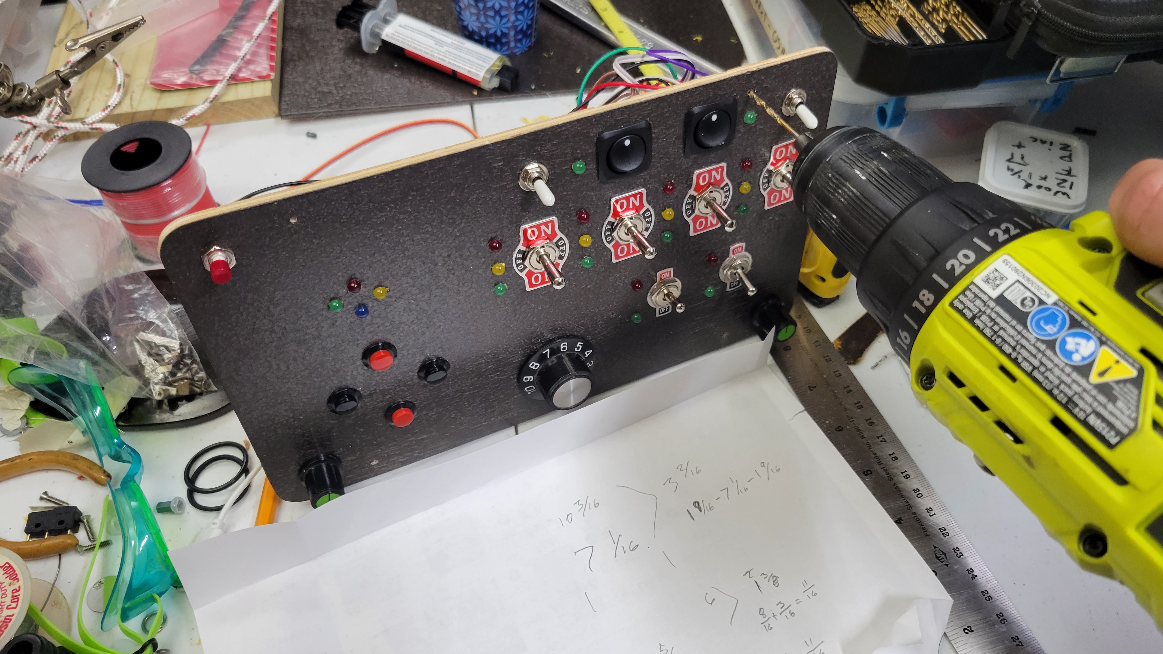
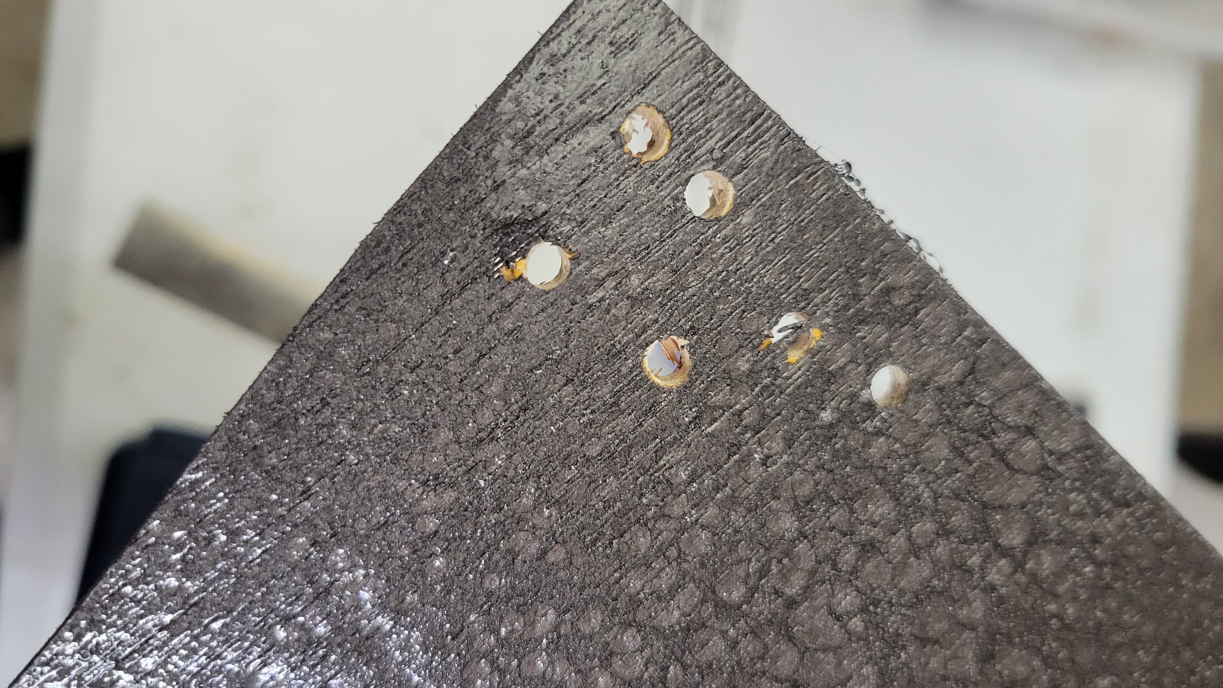
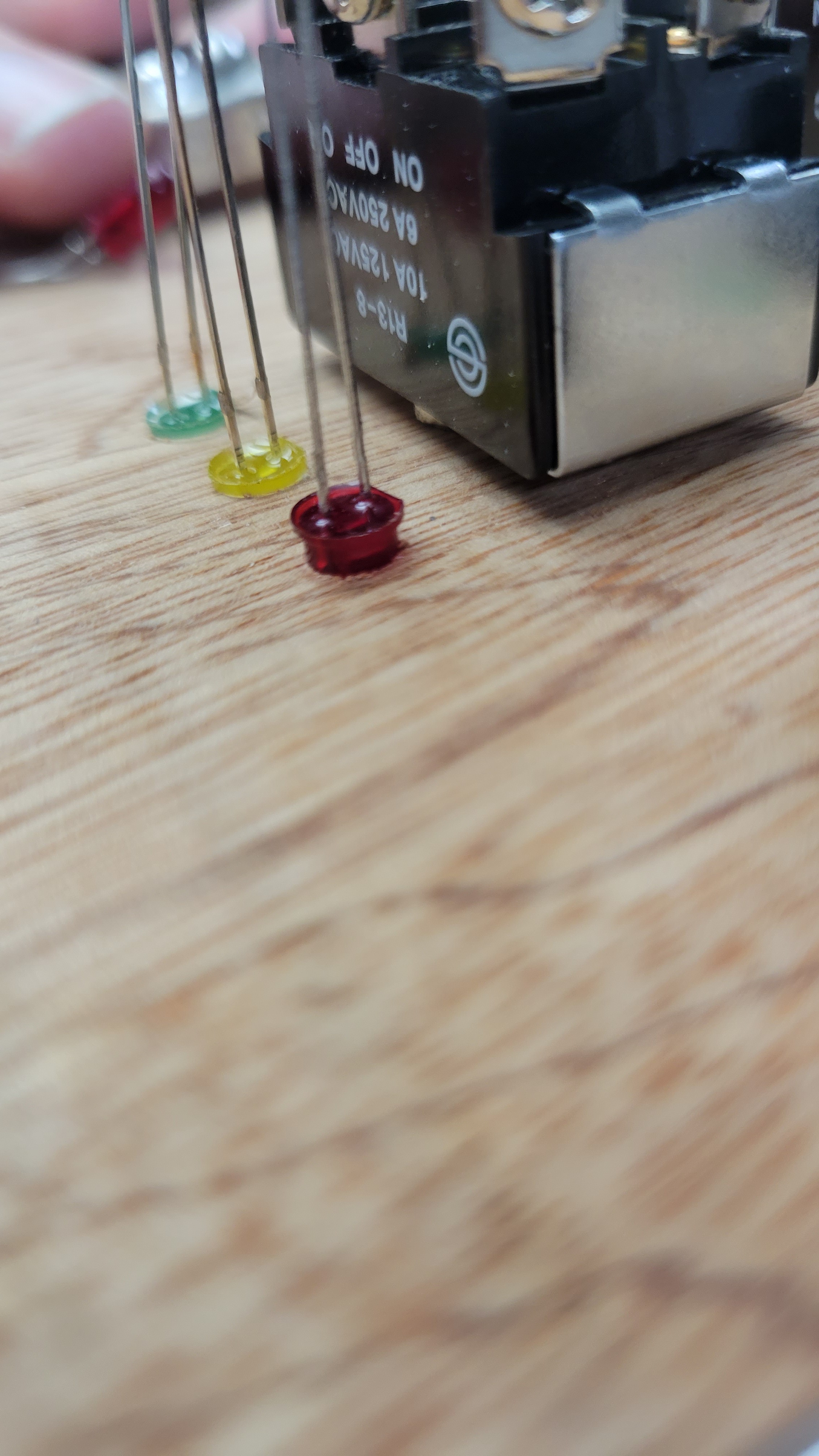
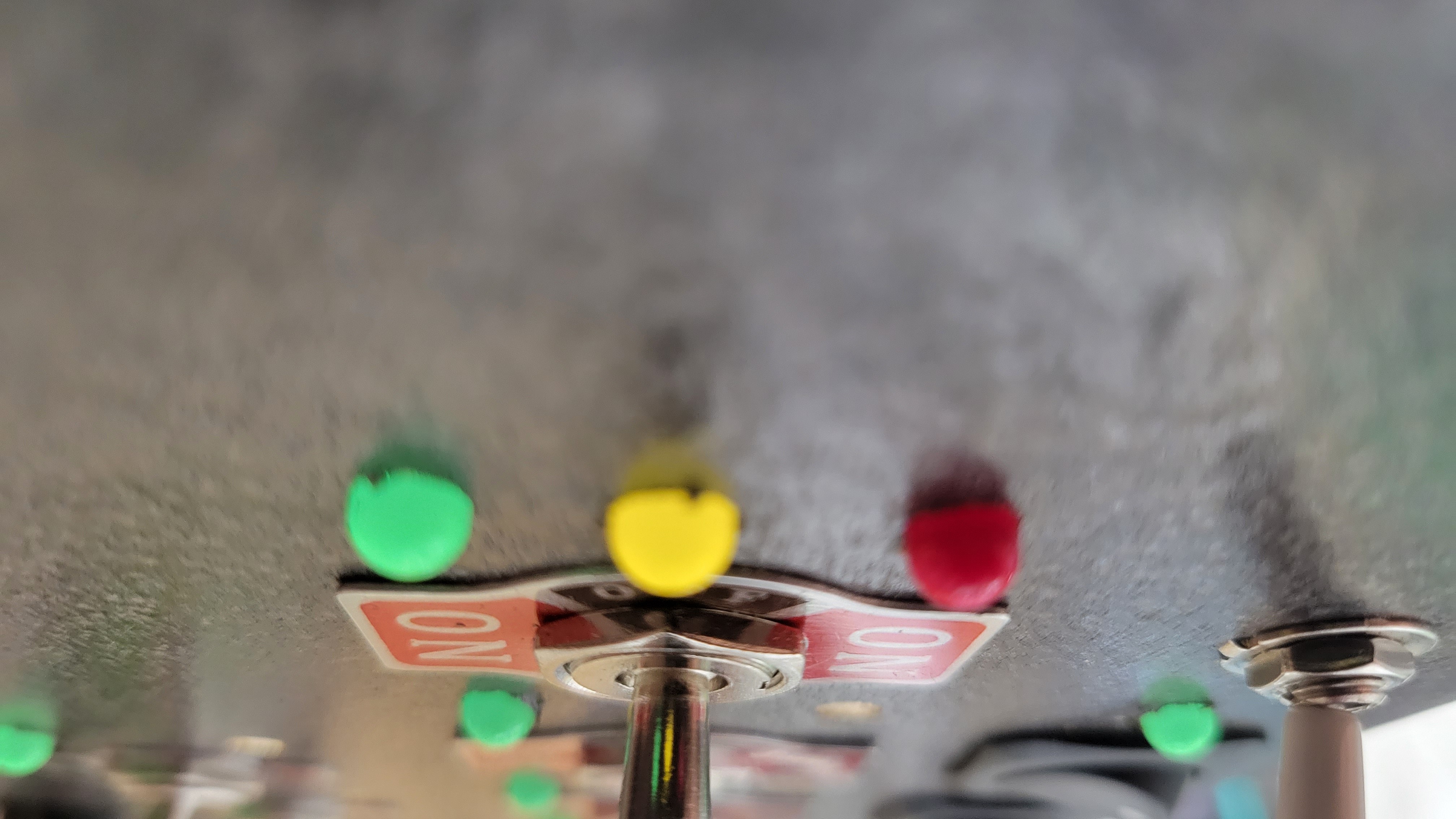
    To install the LEDs I tried simply drilling a hole slightly smaller than the LED and press fitting it. This didn't work because it actually pushed up the top laminations of the wood. So I used a slightly bigger bit that was the same size as the LED. This worked very well since the LED is actually have a very slight taper that I hadn't considered. 

    I also found that if I drilled from the top, the drill would cause some delamination. So I tried from the bottom instead and if I went slow it actually created a fairly clean hole on the top. In order to locate the LEDs, I actually simply eyeballed the placement and used a spring-loaded center punch to start a hole on top. Then I drilled through with a small pilot drill, flipped over the board and finished each hole slowly with the full-size drill.

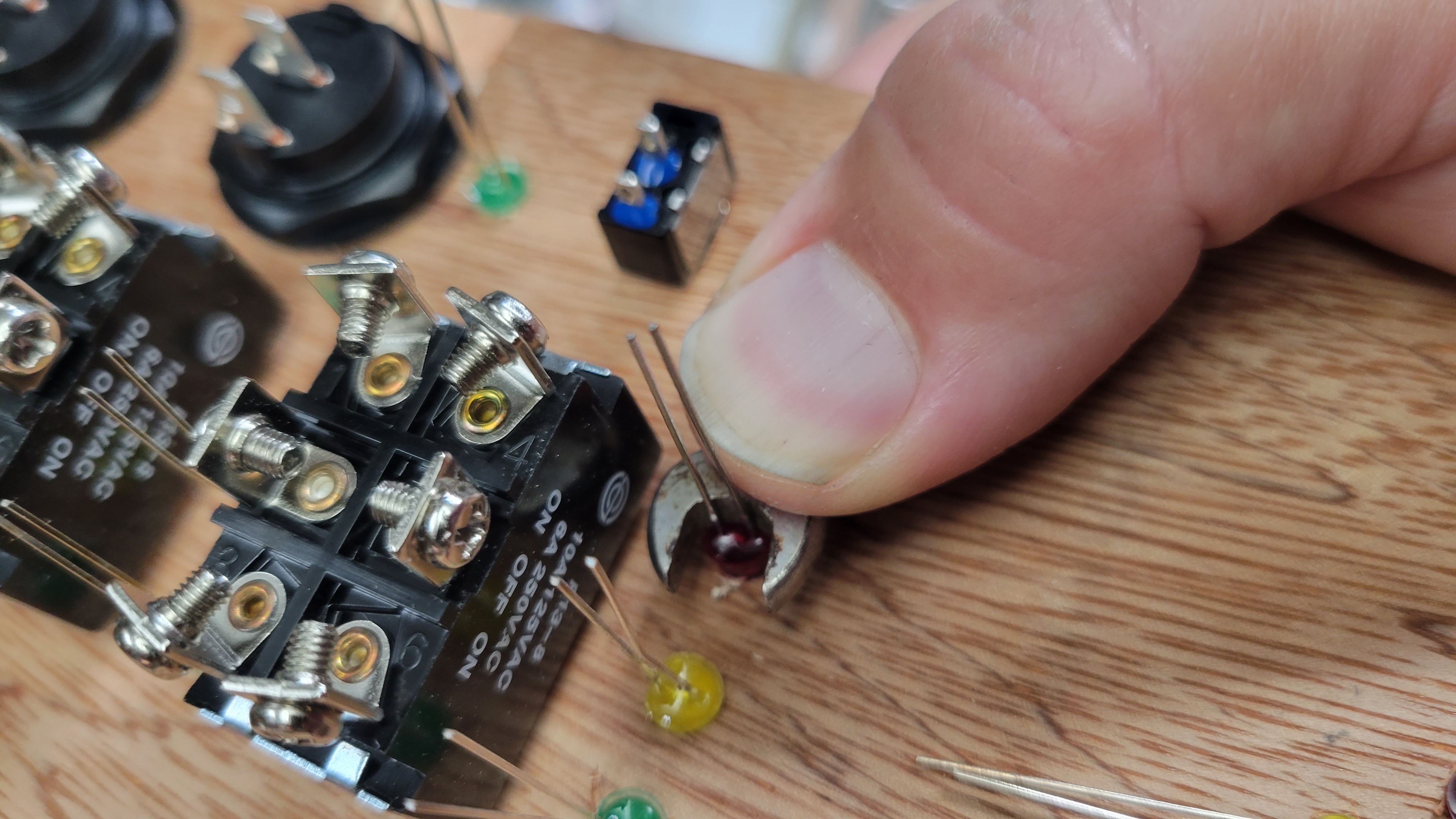
    I used to very small wrench in order to get enough leverage to push them in. I don't think they will be falling out even without any glue, however I am giving this to a toddler and I could be very wrong if he decides to start whacking it with a hammer (which is not out of the question for him!)

    Next I need to prototype all of the mounting by putting things in place with hot glue. If it all fits well then I can start wiring which may take me the rest of the week! There's a lot of wires in this thing...

    Pics:

    Test holes. Hole on the left delaminated.

  • Firmware V0.1 Complete

    Josh07/18/2023 at 22:12 0 comments

    Just over a week of chatting with ChatGPT-4 and I have working code! At least it works on wokwi.com... I still need to load it to the real hardware. 

    It works, but there are a few things I don't like:

    1. The array of "all leds" doesn't include the simon says leds.
    2. The dimming is a little funny because I wanted the pots to do something but I'm leaving the addition of .96" OLED screens for a later upgrade. 
    3. It doesn't have any "cool" things like patterns or dimming when it is turned on.
    4. It was written by a LLM and I have not tried any optimization at all.

    But since it works, I need to STOP coding and work on other stuff... like building the physical hardware. I have 4 days left.

    Here it is in all its glory, or shame...

    // -----------------------------Include libraries -------------------
    #include <Arduino.h>
    
    // -----------------------------Define variables----------------------
    int debounceDelay = 50;
    int minLEDdim = 10; // minimum LED dim level (never let the pots turn the LEDs off completely)
    
    // -----------------------------Define structures---------------------
    struct Switch {
      String name;
      int pin1;
      //  int pin2;  // for SP3T, 0 for SPST (pin 2 is always gnd - no definition req'd)
      int pin3;  // for SP3T, 0 for SPST
      int state1; // the states match the LED structure for easy matching
      int state2; // this will be set to high if state 1 and 3 are low 
      int state3; // this should initialize at low and stay low for SPST switches (which don't have a third state)
    };
    
    struct LEDSet {
      String name;
      int dimPin; // for sets of leds that only have one, only the dim pin and dim level is used
      int pin1; // Used for 2 or 3 LEDs, 0 if 1 LED
      int pin2; // Used for 2 or 3 LEDs, 0 if 1 LED
      int pin3;  // Used for 3 LEDs, 0 otherwise
      int state1;
      int state2; 
      int state3;
      int dimLevel;
    };
    
    struct Button {
      String name;
      int pin;
      int state;
      int lastState;
      unsigned long lastDebounceTime;  // add debounce time
      //int debounceDelay;  // the debounce time; increase if the output flickers
    };
    
    struct Potentiometer {
      String name;
      int pin;
      int state; //this will utilize the analog in values from 0-1024
    };
    
    struct SimonLED {
      String name;
      int dimPin;
      int dimLevel;
      unsigned long turnOffTime;
    };
    
    // ----------------------instances of structures----------------------------
    // Switch instances (set here is teh set of data for one switch)
    // struct: name, pin 1, pin 3, State 1, State 2, State 3)
    Switch SWset1 = {"PowerSwitch1", A13, 0, LOW, LOW, LOW};
    Switch SWset2 = {"PowerSwitch2", A14, 0, LOW, LOW, LOW};
    Switch SWset3 = {"SelectionSwitch1", A12, 0, LOW, LOW, LOW};
    Switch SWset4 = {"SelectionSwitch2", A15, 0, LOW, LOW, LOW};
    Switch SWset5 = {"SP3T1", 22, 23, LOW, LOW, LOW};
    Switch SWset6 = {"SP3T2", 24, 25, LOW, LOW, LOW};
    Switch SWset7 = {"SP3T3", 26, 27, LOW, LOW, LOW};
    Switch SWset8 = {"SP3T4", 28, 29, LOW, LOW, LOW};
    Switch SWset9 = {"SPST1", A10, 0, LOW, LOW, LOW};
    Switch SWset10 = {"SPST2", A11, 0, LOW, LOW, LOW};
    
    // LED instances (set here is up to 3 LEDs and associated with the same switch number)
    // struct: name, dim pin, pin 1, pin 2, pin 3, State 1, State 2, State 3, dimlevel)
    LEDSet LEDset1 = {"PowerLED1", 6, 0, 0, 0, HIGH, HIGH, HIGH, 128};
    LEDSet LEDset2 = {"PowerLED2", 7, 0, 0, 0, HIGH, HIGH, HIGH, 128};
    LEDSet LEDset3 = {"null", 0, 0, 0, 0, HIGH, HIGH, HIGH, 0};
    LEDSet LEDset4 = {"null", 0, 0, 0, 0, HIGH, HIGH, HIGH, 0};
    LEDSet LEDset5 = {"SP3TSetLED1", 2, 30, 31, 32, HIGH, HIGH, HIGH, 128};
    LEDSet LEDset6 = {"SP3TSetLED2", 3, 33, 34, 35, HIGH, HIGH, HIGH, 128};
    LEDSet LEDset7 = {"SP3TSetLED3", 4, 36, 37, 38, HIGH, HIGH, HIGH, 128};
    LEDSet LEDset8 = {"SP3TSetLED4", 5, 39, 40, 41, HIGH, HIGH, HIGH, 128};
    LEDSet LEDset9 = {"SPSTSetLED1", 44, 43, 42, 0, HIGH, HIGH, HIGH, 128};
    LEDSet LEDset10 = {"SPSTSetLED2", 45, 49, 48, 0, HIGH, HIGH, HIGH, 128};
    
    // Potentiometer instances
    Potentiometer Pot1 = {"Potentiometer1", A0, 0};
    Potentiometer Pot2 = {"Potentiometer2", A1, 0};
    Potentiometer Pot3 = {"Potentiometer3", A2, 0};
    
    // Create instances...
    Read more »

  • Wires Everywhere

    Josh07/17/2023 at 17:28 0 comments

    Yesterday I got a set of breadboard hook up wires. I like to use these because they're already in ribbons and include the pins I can plug directly into the Arduino. A simple lunch task was pulling the ribbons apart in groups according to the switch and LED groups unplugging them into the proper place on the Arduino. 

    After work today I will get out the hot glue gun and start fixing them in place. Hot glue is great because it holds pretty well and I can peel it off later if needed. I'm tempted to super glue the groups together to make plugs but we'll see if I need to do that; they're wedged in pretty tight right now.

View all 14 project logs

Enjoy this project?

Share

Discussions

diesalott wrote 08/18/2023 at 12:44 point

I heart this soo much! Soo many ideas?

  Are you sure? yes | no

thekanester wrote 08/18/2023 at 11:55 point

The engagement on the little man's face is priceless. He'll remember this.

  Are you sure? yes | no

mkdxdx wrote 08/18/2023 at 09:28 point

Briliant idea and execution!

But aren't you afraid your kid might one day blame you for his fall into DIY/hacking/tinkering rabbithole? :D

  Are you sure? yes | no

Weinbergersonburnan wrote 07/20/2023 at 10:57 point

That's an awesome project for your son! A box of switches sounds like a lot of fun for him. And turning it into a cyberdeck with lights and switches is even more exciting! Your hacker dad skills will surely  impress him, and documenting it for the cyberdeck challenge is a fantastic idea. Have a blast building it, and I'm sure your son will love it for more visit https://cryptopostage.info/tracking

  Are you sure? yes | no

Josh wrote 07/27/2023 at 14:20 point
Thanks!

  Are you sure? yes | no

Josh wrote 07/11/2023 at 22:41 point
Found a link to the uC on the video display.

http://www.zxfelec.com/mainchip-v100.html

  Are you sure? yes | no

Similar Projects

Does this project spark your interest?

Become a member to follow this project and never miss any updates