-
1WARNING:
ANY PROJECT THAT USES LITHIUM BATTERIES MAY RESULT IN FIRE OR OTHER BAD THINGS. USE THESE INSTRUCTIONS AT YOUR OWN RISK.
-
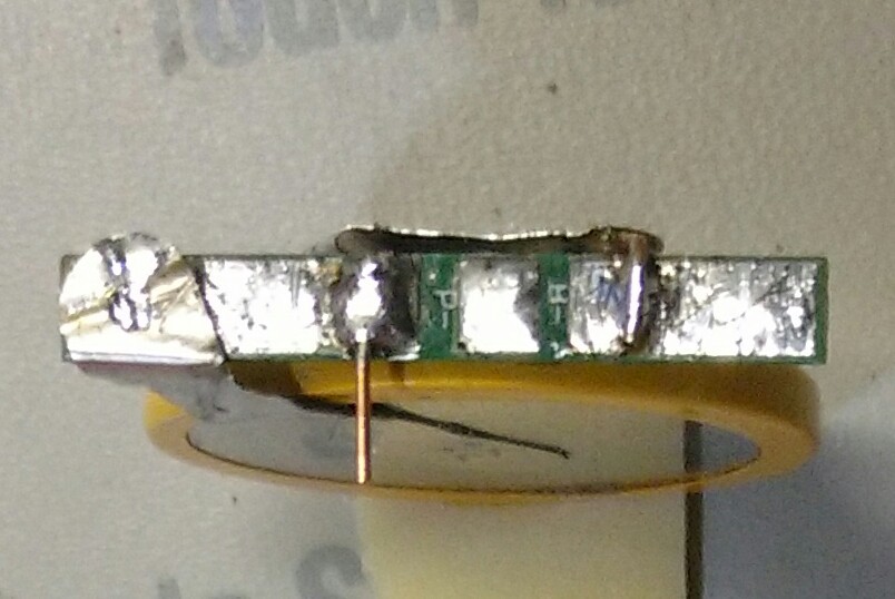
2INSTALL THE POWER SWITCH AND CHARGING JACK
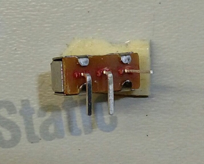
Bend the leads on the switch as shown below:
![]()
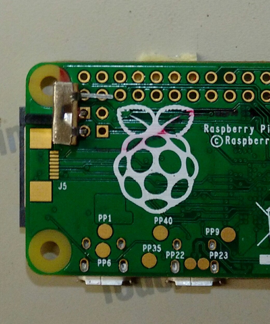
Solder to the Zero as shown below. Do not solder the unbent lead:
![]()
Below the switch attach the female header plug with foam tape, but don't connect the wires to anything yet.
-
3PREPARE THE BATTERY TABS
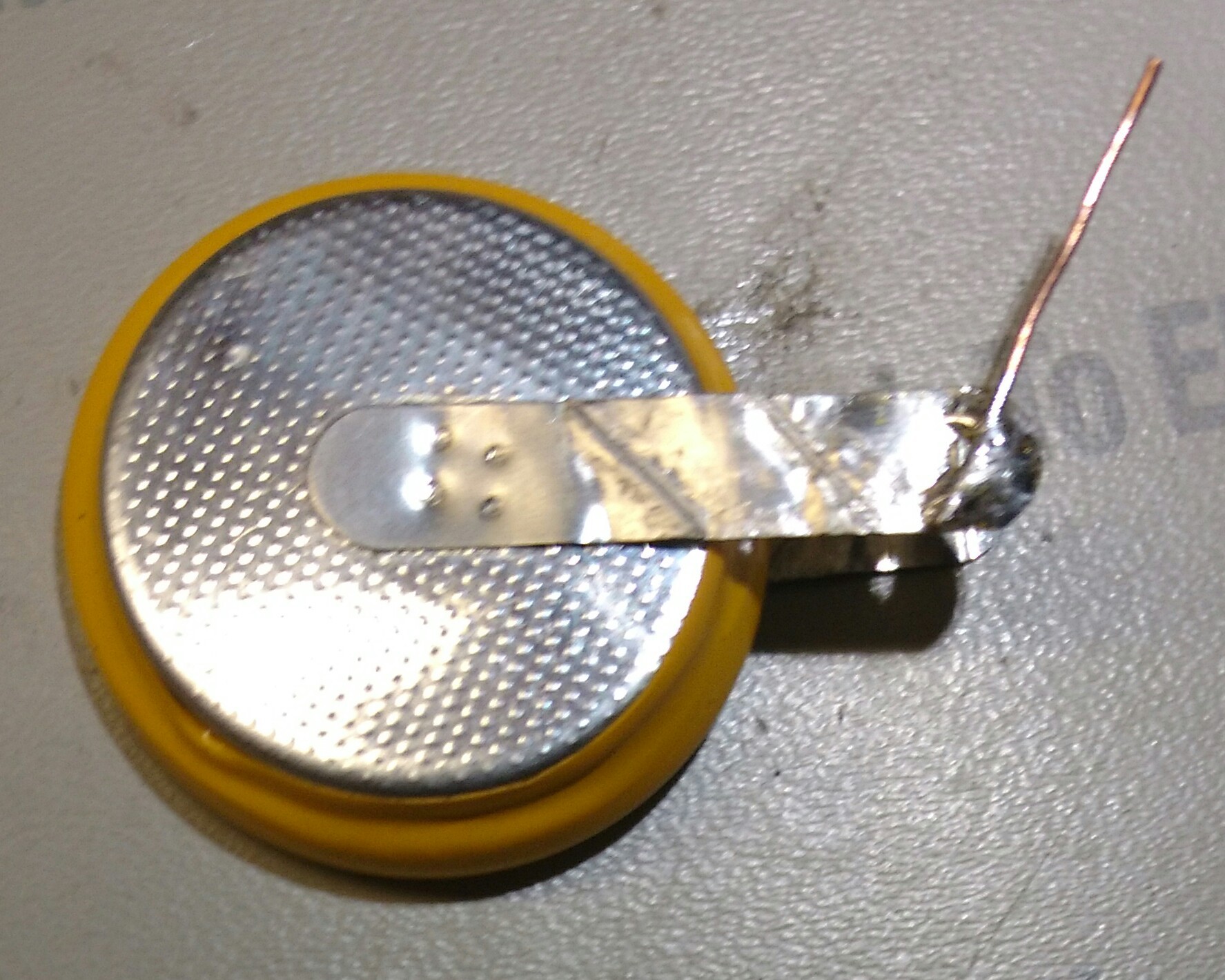
Solder a short wire to the negative battery tab as shown below:
![]()
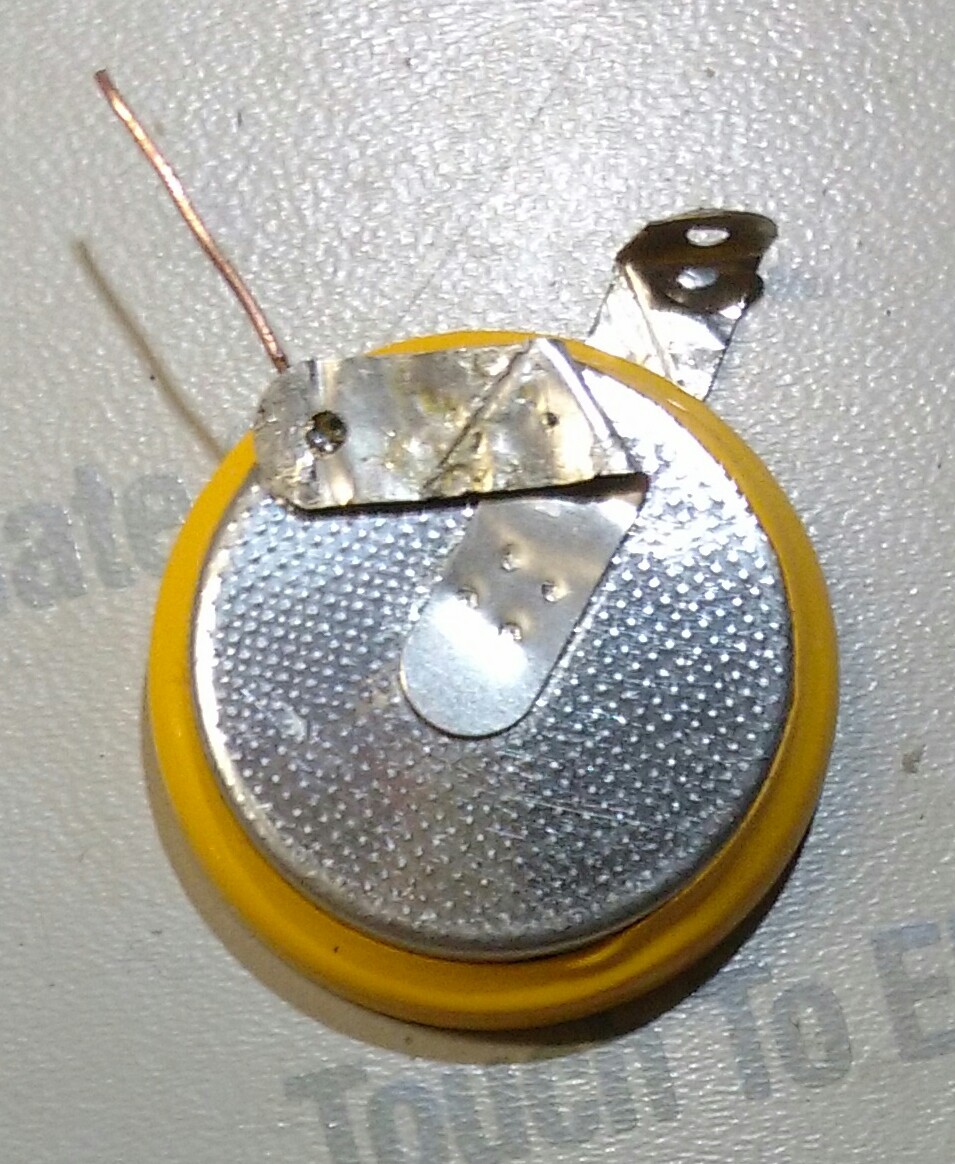
Bend the battery tabs like this:
![]()
-
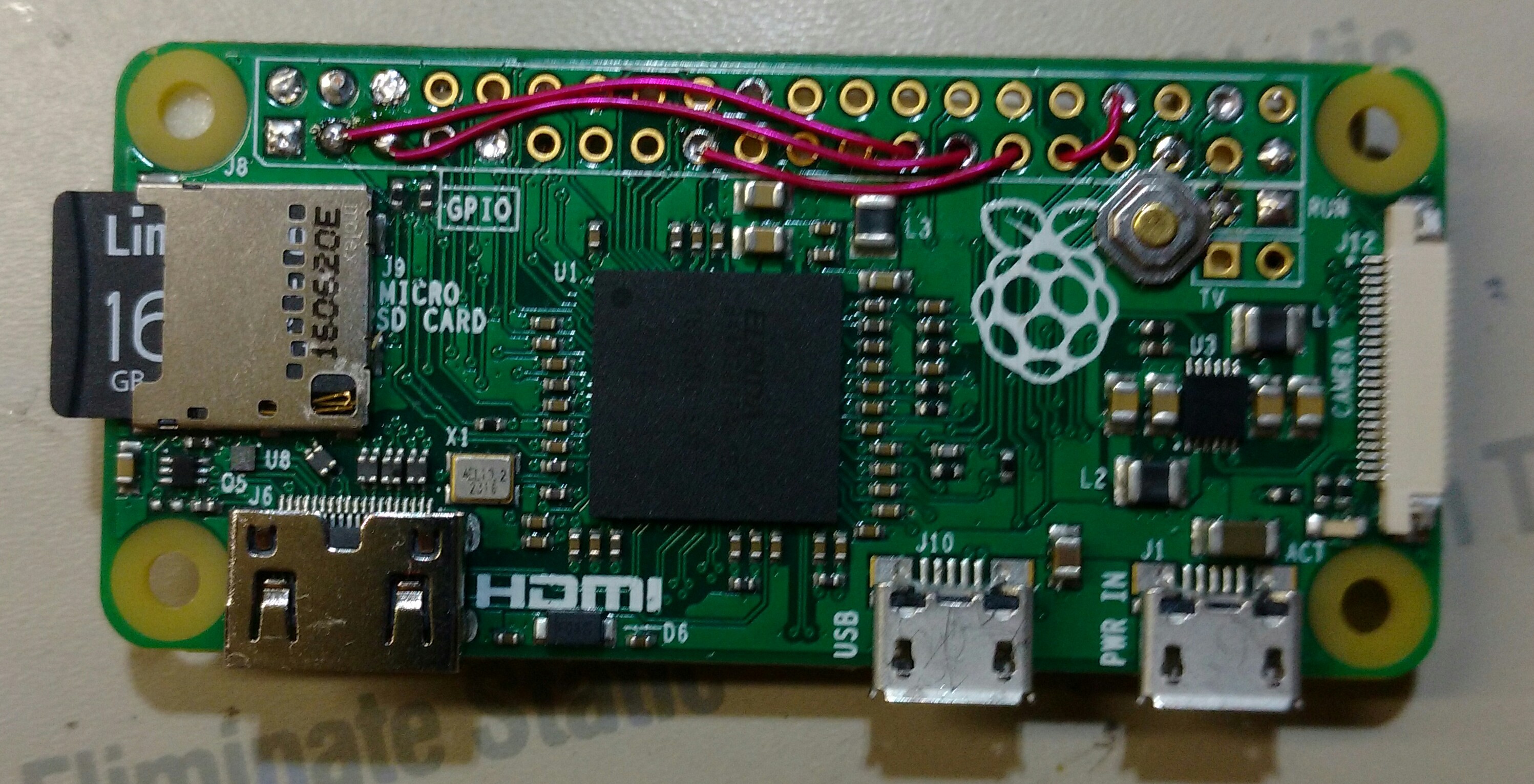
4INSTALL THE DISPLAY
Remove the pins from the display. Solder 2 inch wires to the 4 holes the pins were soldered to. Make sure the insulation is right next to the board.
Apply foam tape to the back of the display. You'll have to use 4 small pieces since there are components on the back. Guide the wires through holes in the Pi as shown below and stick it down:
![]()
Strip and solder the wires to the appropriate pins: GND to Pi GND, VDD to Pi 3.3V, SCK to Pi I2C clock, SDA to Pi I2C data. The 4 GPIO holes below the display are being used as feed-throughs: make sure the wires are well insulated and don`t make electrical contact as they pass through.
-
5WIRE THE CHARGING JACK
Cut off the wire on the jack nearest the edge of the Pi. We won't need it. Strip and solder the middle wire to the P+ terminal on the protection board.
Strip and solder the remaining wire to the unbent pin of the switch. Be careful the previously soldered wire doesn't come loose.
-
6CONNECT THE BATTERY
Solder the lower tab (the one with the bent up end) to B+ on the protection board.
Make sure there isn't any unwanted electrical contact from the tab to the protection board. If so, insulate with tape or paper.
Solder the wire from the top tab to B- on the protection board.
Solder a short piece of wire to P+, pointing down. It will go through one of the Pi's 5V holes, so position it accordingly.
It should look like this when you're done:
![]()
Apply double sided foam tape to the battery, and while guiding the wire through the appropriate hole, attach the battery to the Pi. Make sure you use enough foam tape to cover all of the battery, including the lower tab. It will insulate the battery from the Pi. Solder the wire to the Pi.
Turn the power switch off (slide it toward the charging connector). Strip and solder a wire from P- to the un-bent terminal on the power switch.
If your protection board isn't labeled you can figure out the connections easily. The B terminals are usually on the ends. If you removed the board from a cell, they're the terminals that the battery leads attached to. The P terminals are the other two. B+ is directly connected to P+. You can check with a meter or look at the copper traces on the board. P- connects to one side of the MOSFET, and B- connects to the other side. Sometimes there are two MOSFETs, either in series or parallel.
-
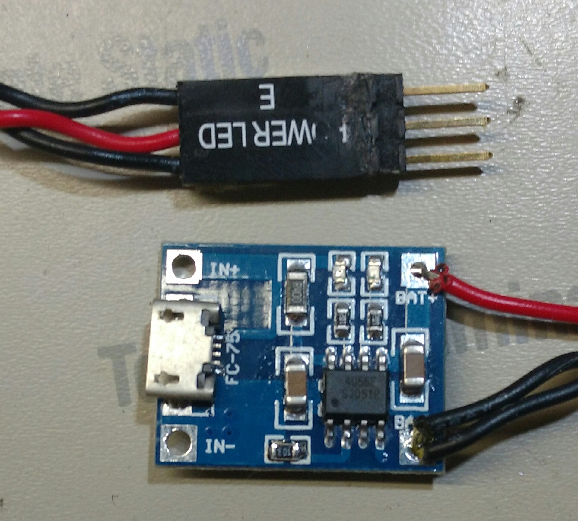
7WIRE THE CHARGING BOARD
Replace the charging current set resistor on the charging board with the 12K one. It connects from pin 2 of the IC to IN-, and is 1200 ohms as shipped from the factory. It's the resistor at bottom center in the photo below. Your board may differ:
![]()
Strip and solder the 3 pin male plug to the output terminals, center wire to BAT+ and both outside wires to BAT-.
-
8USAGE INSTRUCTIONS
IMPORTANT: Make sure the Pi is switched off when charging!
Add the following to /boot/config.txt:
dtparam=i2c_arm=on,i2c_baudrate=400000
To turn off HDMI output and increase battery life, add the following to /etc/rc.local:
/usr/bin/tvservice -o
I used the OLED96 library to write to the display, located here.
Discussions
Become a Hackaday.io Member
Create an account to leave a comment. Already have an account? Log In.