-
Application Ideas
01/06/2018 at 01:27 • 0 commentsThis basic circuit can be the building block for other system designs. Some of the ideas we came up with are the following:
1. Wireless Data Transmitter Sensor Nodes: The system can be collecting data any sensor and transmit it wirelesslly. The system will implement the low power modes of the MAX32625 to extend the battery life. The best wireless solution to incorporate are low power transceiver devices, like a BLE or LoRa.
2. Smart Data Logger: The MAX32625PICO can monitor events in low power mode from any senor via the PMU (Periferal Management Unit). A key event will triggering the logging of valuable data or the reprogram of the mission. The characteristics measured can be altitude, humidity, motion, and/or time.
3. iButton data logger Setup, Backup and Smart battery management: The MAX32625PICO can be programmed to deploy an iButton mission, which is essentially the programming required for the iButton to collect data at a determined interval. The microcontoller can maximize the battery of the iButton, by enabling and disabling the internal RTC clock of the iButton and only enable when the collection is required. This design can be enhanced by a wireless interface as mentioned above.
-
Prototype!
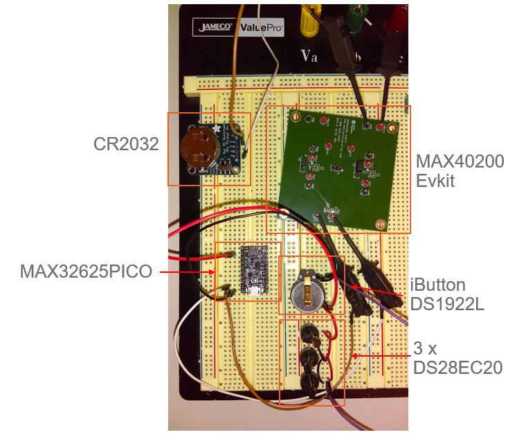
01/06/2018 at 00:55 • 0 commentsHere's a prototype of our data logger system! Look how small the PICO board is compared to the battery! The size of the end system can be a lot smaller than this. MAX40200 is available in WLP and SOT23 package, and DS28EC20 is available in TSOC and TDFN packages on top of the TO92 package being used for prototyping.
-
System Diagram
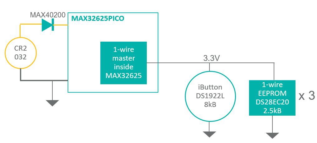
01/06/2018 at 00:09 • 0 commentsThe block diagram above illustrates a data logger backup system using the MAX32625PICO and three DS28EC20's, which are 2.5kB 1-wire EEPROMs.
The data logger of interest is DS1922L, which is a temperature logger with 8kB Data-Log Memory. The DS1922L is a rugged stand-alone temperature logger capable of storing temperature data for long periods of time (years!), making it suitable to be deployed in the fields. However, once the battery internally is depleted, all the data stored previously would be lost. The backup system powered by a single coin cell battery ensures that measurements logged by the iButton remain intact even if the battery of the iButton dies.
1. MAX32625 has a hardware 1-wire master that can be used to communicate with any 1-wire slave devices except EPROMs since the PICO is not equipped with a 12V programming pulse circuitry. 1-wire is useful as it only requires one wire for power and communication, and another for ground. Each 1-wire device is equipped with unique 64-bit ROM IDs so unlike I2C, multiple 1-wire slaves with the same part number can be placed on the same bus without needing to worry about address collision.
2. Three DS28EC20s, which can store 2.5kB each, are required to back up 8kB data.
3. The PICO board will fetch temperature measurements from the iButton periodically, and save them to the EEPROM. Firmware will need to be implemented. The OneWire library is available on mbed and will be used as the API to communicate with the data logger and the memories. https://os.mbed.com/teams/Maxim-Integrated/code/OneWire/
Note: Even though iButton was the data logger of interest, the data backup system can extend to any other sensors and data loggers with compatible interfaces to the PICO board (SPI, I2C, 1-wire). More 1-wire EEPROMs can be added on the 1-wire bus if more memory is required. Alternatively, there are also flash memories with SPI interface available.
For more information on 1-wire, please refer to https://www.maximintegrated.com/en/app-notes/index.mvp/id/1796
Datasheets can be found below:
MAX32625PICO: https://datasheets.maximintegrated.com/en/ds/MAX32625PICO.pdf
DS1922L: https://www.maximintegrated.com/en/products/digital/data-loggers/DS1922L.html
DS28EC20: https://datasheets.maximintegrated.com/en/ds/DS28EC20.pdf
MAX40200: https://datasheets.maximintegrated.com/en/ds/MAX40200.pdf
-
Test circuit for battery implementation and protection
01/05/2018 at 23:49 • 0 comments
Coin Cell Operated Pico Board
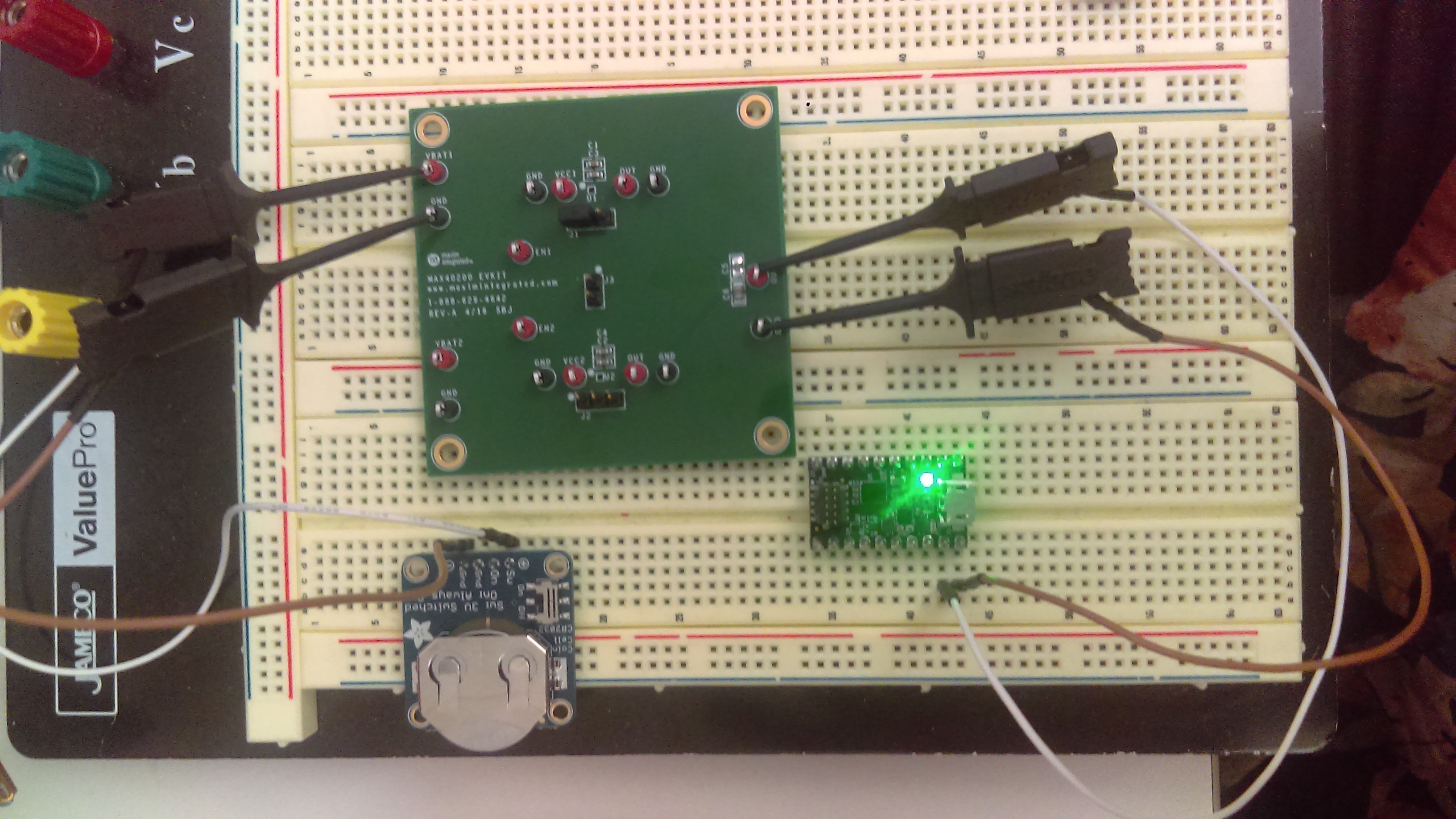
MAX32625PICO can be operated by a coin cell battery, opening up a variety of applications.


