Rue Mohr
-
Images of current sensor board
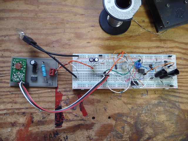
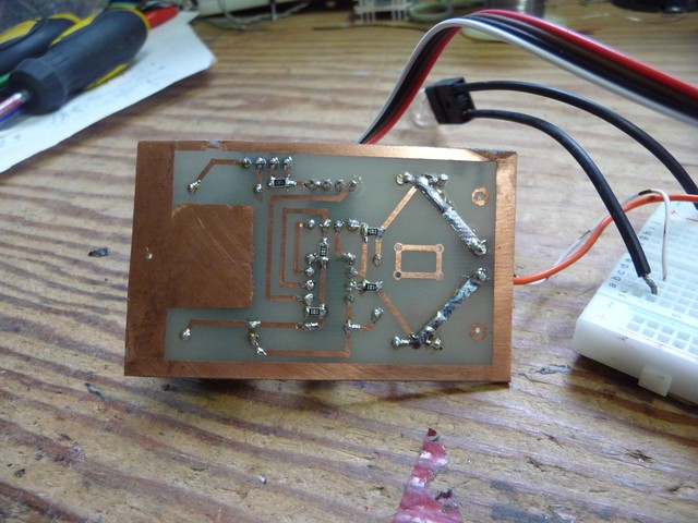
01/22/2015 at 01:29 • 0 commentsLacking anything that can be considered real progress, I'm posting images of progress made since last log.
![]()
![]()
![]()
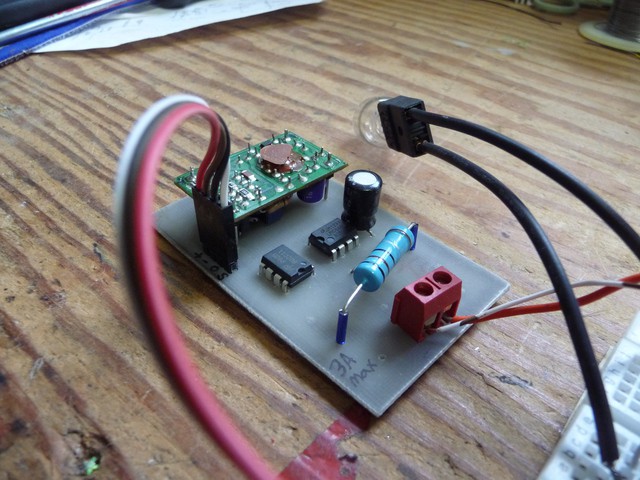
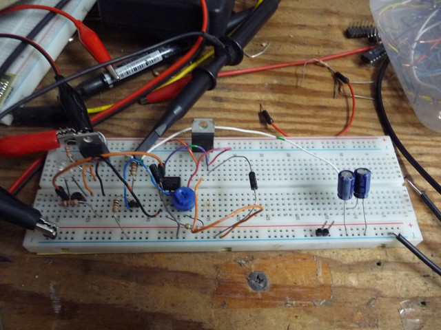
This is it wired up to my linear regulator test. Didn't entirely behave, its like its a science of soemthing :-) the piggyback board is a dc-dc isolator from thinnet ethernet cards (how many people are gonna have to look up that one!) it takes 5V in and outputs 9V, which means that the sensor can go on a power line anywhere from 0 volts up and still provide a 5V sense signal from ground.
And it works great. There are no compensation resistors because its basically a current transformer, 0-5A in causes 0-5mA out, you use a 1k shunt resistor, which you can tweek if you want to play with the output scale.
Latley I use surface mount components where its convienient, if I need to jump .4" while I go thru a resistor, I use a through hole resistor.
+, - is the power in
0,S is the zero ref and signal out
-
I'm not dead yet...
01/13/2015 at 06:27 • 0 commentsgee whiz I need to make you all some more progress on this one. There are some new 3d printed knobs, but they aren't quite right, the printer broke so I'm in a bit of a dependency problem there. The temporary linear regulator was giving me issues, but I was making progress. I also have to make up some side top and bottom plates.
Please stand by.
... oh putz, I didn't post the finished (working!) current sensor board....
-
Current monitor working
11/14/2014 at 03:19 • 0 commentsI have to admit, every time a new person starts following this project I do or post some more progress. :) so thankyou. (your driving this project)
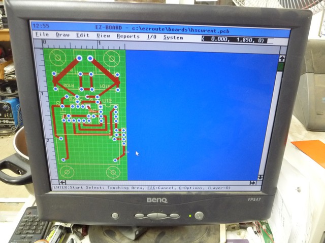
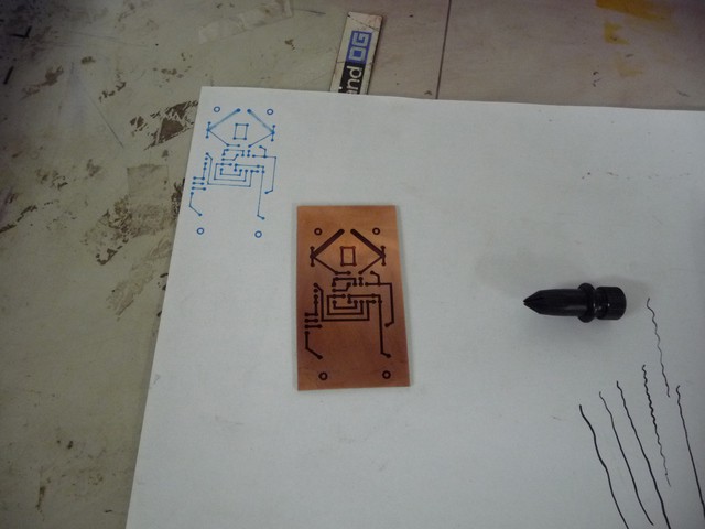
ok, last weekend, I re-tested the current sensor and made some changes to work with the new amplifiers I got (LMC6....LMC6482), because these are rail-to-rail amps, I dont need a bunch of the fuff I did trying to use an LM324.
I have designed and started the print of a PCB for it.
![]()
![]()
![]()
To get the power supply up and going, I'm going to make the power stage of the system a module, which will be linear for now, and I'll change it out for a switching one later.
![]()
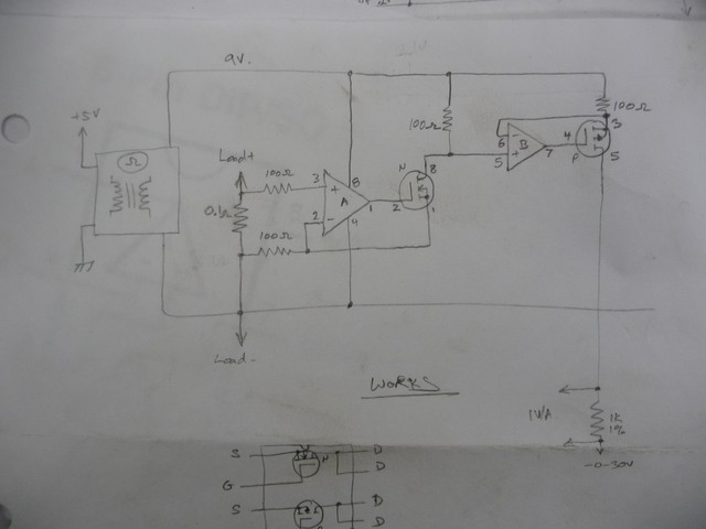
It took a lot of work, but I have managed to get a stable, P channel fet, linear regualtor put togethor. Because of the DAC's I'm using the regulator needs a gain of 12, ( the DACs output a 2.5V range) to its reference signal, not much I can do about that (I'd like it to be a ratio of about 6 or 3, 2 would be ok with me).
I'd also like to thank the HaD crew for fixing the .io site to work properly with my browser!
-
PWM regulator
08/10/2014 at 23:25 • 0 commentshad.io firefox things still not fixed...
So, I been working on getting the pwm regulator thing worked out. over the past few days I been looking at the MC34063, UC3842, and TL494. The 34063 is trickey to get to drive an external fet, the UC3842, without tricks is limited to a miniumum voltage of 2.5V. The TL494 is not a great design fit either. So, right now I have a LM339 based pwm genorator running on the bench, at 100kHz, which seems to be a fine freq (not too low, not too high).
The bulk supply I have in it can output up to 36V, my peak design output is 30V, so the converter needs a duty higher than 83% (+- losses). 5A, so, all the design specs are comming togethor. I'm expecting to use a discontinious mode converter, this should help handle the range of voltages and currents its dealing with.
Posting the avr firmware is still on my todo list!
Not much to take pictures of, my appologies.
It turns out that the 3842 has about .2V schmitt on its votlage error amp, meaning the output ripples by that much, that wont do!
After a few itterations, this is quickly moving towards a set of analog regulation amplifiers that output to a PWM power stage. Part of the trick is to find comparitors for the pwm that are fast enough for the switching. I dont think I'm gonna make 300Khz, oh well. I suppose I could implement a sloppy pwm regualtor to get the supply up and tune it later, I'm really itching to have a better supply.
-
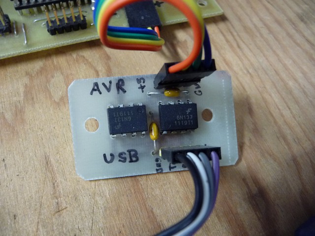
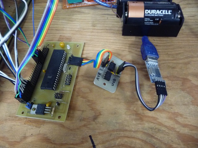
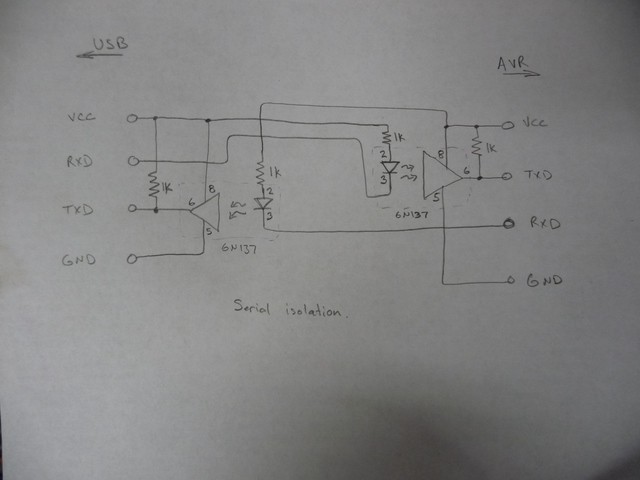
Serial Isolation working
07/25/2014 at 14:15 • 0 commentsThe 6n137 worked great for isolating the serial at a ttl level, full baud rate isn't a problem.
![]()
![]()
Cant say the same thing about hackaday.io when used with iceweasel.
I will made a point of posting the isolator schematic (its pretty straight forward if you get your pullup resistors the right way around)
![]()
I really have to make the new buck converter now, I keep putting it off... I got the P channel fets and they are great. One of them is running a solar project at the moment.
I hearby click publish trusting my text will not dissapear...
![]()
-
iceweasel test
07/25/2014 at 14:05 • 0 comments -
encoders mounted
06/17/2014 at 04:33 • 0 commentsI have finished replacing the 4 pots with encoders, I need to mount the microcontroller in the frame.
Thats all, stay tuned.
-
All input mechanisms working
06/16/2014 at 02:10 • 0 commentsToday I got the encoder control inputs working, this means that all the controls, knob and usb interface work. I settled on having the voltage knobs default to .05V steps (1V/turn) with 1V steps when pushed in. The current knobs do .01A/step with 0.5A when pushed in. I might adjust those later, for now they seem like reasonable values. No converters assembled yet :/ I'm just saving the best part for last.
I resorted to ordering some 6N137 to isolate the serial link, they look fast enough to level shift the pwm, I shall see. 22 days for those to arrive, please stand by.
Switching to encoders means my knobs dont fit anymore, The ones I like are $3 ea online, so I'm tempted to make my own (hobbyist time is free) in the meantime I'll use whatever fits.
-
After a pause, progess continues
05/04/2014 at 05:07 • 0 commentsCant add text from iceweasel, ok. Updates will be few between as I dont get to the computer with chrome on it much.
So far I have a good start on the usb control part of the firmware, I have a working DAC code sample. The DAC I chose, ( PT8211 ) has a 2.5V range centered around 2.5V, so I'v obtained some MCP6002 to expand it to a 0-5V range if I need to. The DAC DOES hold dc values, many people suspected it wouldn't. I have two tiers to progress, one is to install the avr with a usb conntection isolated on the 5V ttl level. I may post code and images on my website.
After a wait, the P channel mosfets I wanted have come in, 20mR (yay) (IRF4905) so I have set forward designing the power side of the converters. for a converter bucking 32V to the 0.3-30V range, at .1-10A range, it looks like I need a 2mH inductor, I'm not sold on that number, I'm gonn try some things out.
I bought a component tester (the mega328 based one) from ebay, it worked long enough to give me an idea how neat it would be to have one. I'm left needing to make an inductance measuring setup (my meter dosn't go low enough) which isn't hard with a fet and the scope.
Tommorow I plan on roughing togethor an open-loop buck converter and trying it out.
No, converter isn't assembled yet, but I have the new op-amps I wanted. LMC6482.
-
Controls and new converters
03/29/2014 at 09:05 • 0 commentsI'v made progress on project design, hopefully I'll make more progress writing about it soon.
Bench power supply
USB and manual control, and monitoring, 2 channel 5A 30V bench supply.