AVR
AVR-
Silicone Sealing of Fence Posts
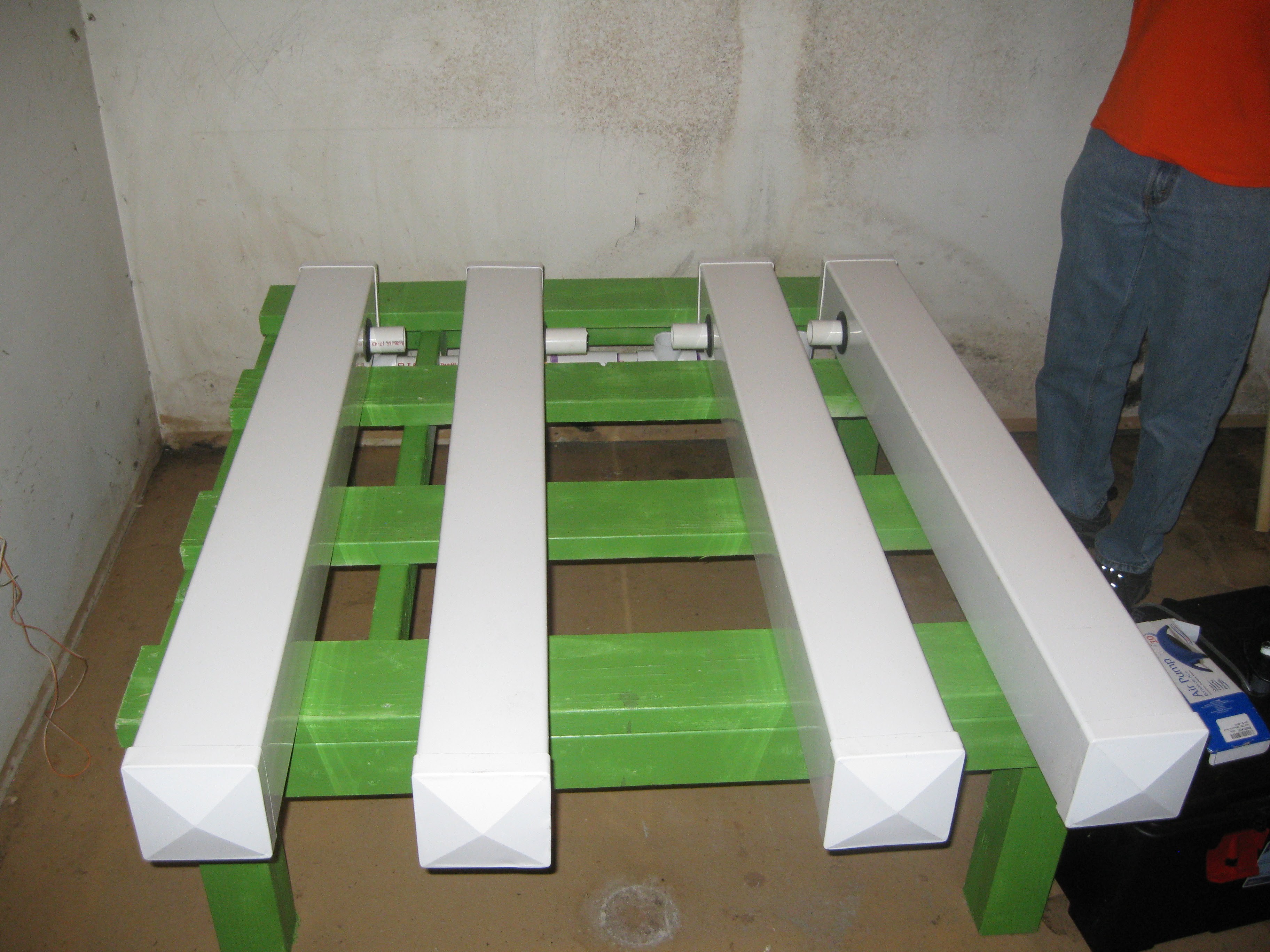
09/13/2015 at 07:45 • 0 commentsShort update. In this update the fence post endcaps that were previously glued with the white gel PVC cement were externally sealed. The end caps or tops for vinyl fence posts don't have the same snug fit that PVC pipe encaps have. One of the ways to make a tight seal is to use the fence post cement sold in the same section as the post at the hardware store, its a PVC cement that seems to have PVC dissolved in it to make it thicker. Anyways in the case that the PVC cement didn't make a perfect seal when gluing the cap/top in place the outside seem of each cap on each end was sealed with silicone. Standard silicon you can find in a hardware store is fine, we used a caulking gun to apply it and pressed it in with finger tips.
First dismantled the grow system, I really am liking my design choice in regards to the easy disassembly, I've had to pull it a part a few times and its just so easy!
![]()
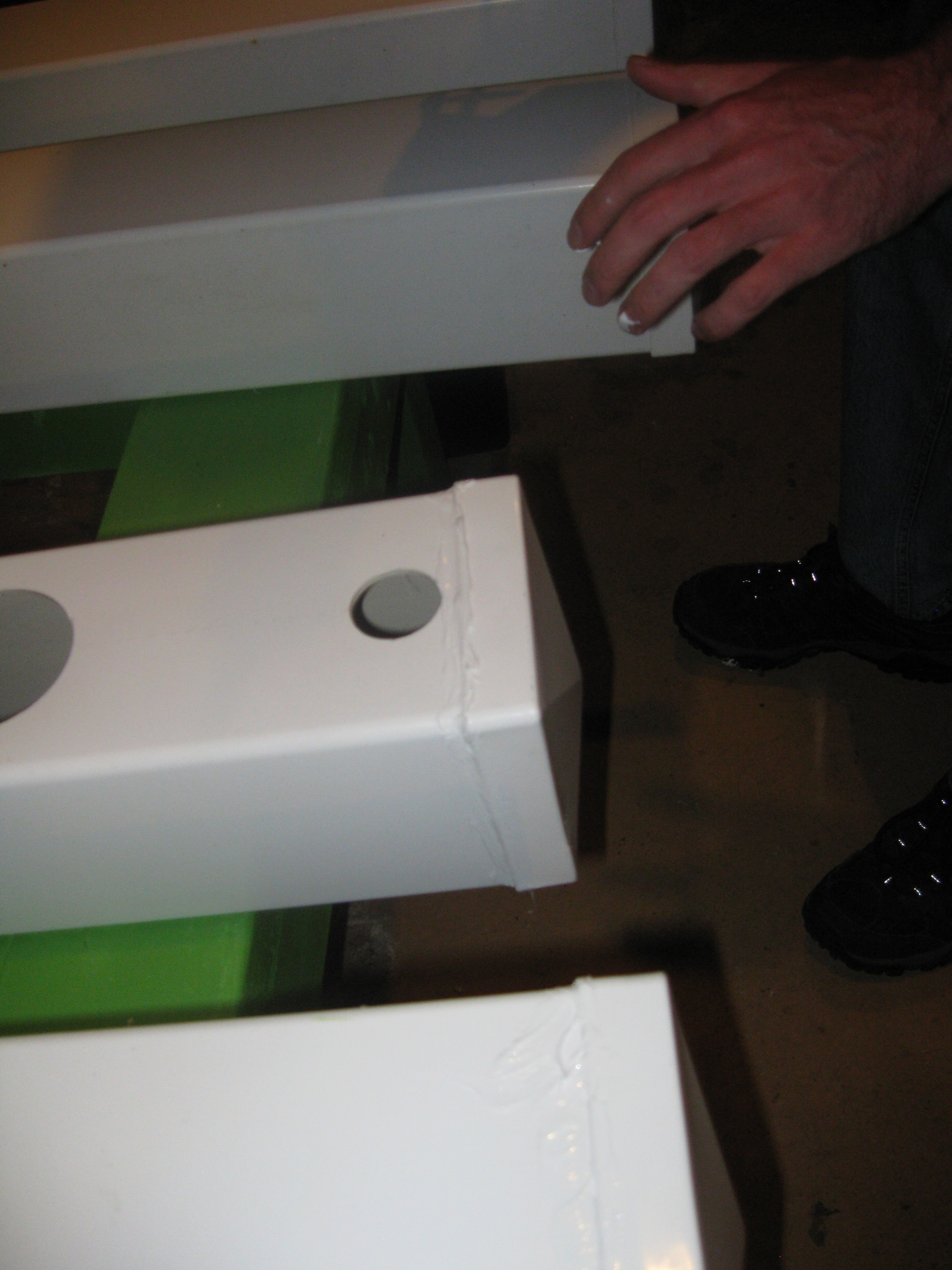
Applied to the first end of the first post, looks messy but it doesn't matter as long as the water stays in.
![]()
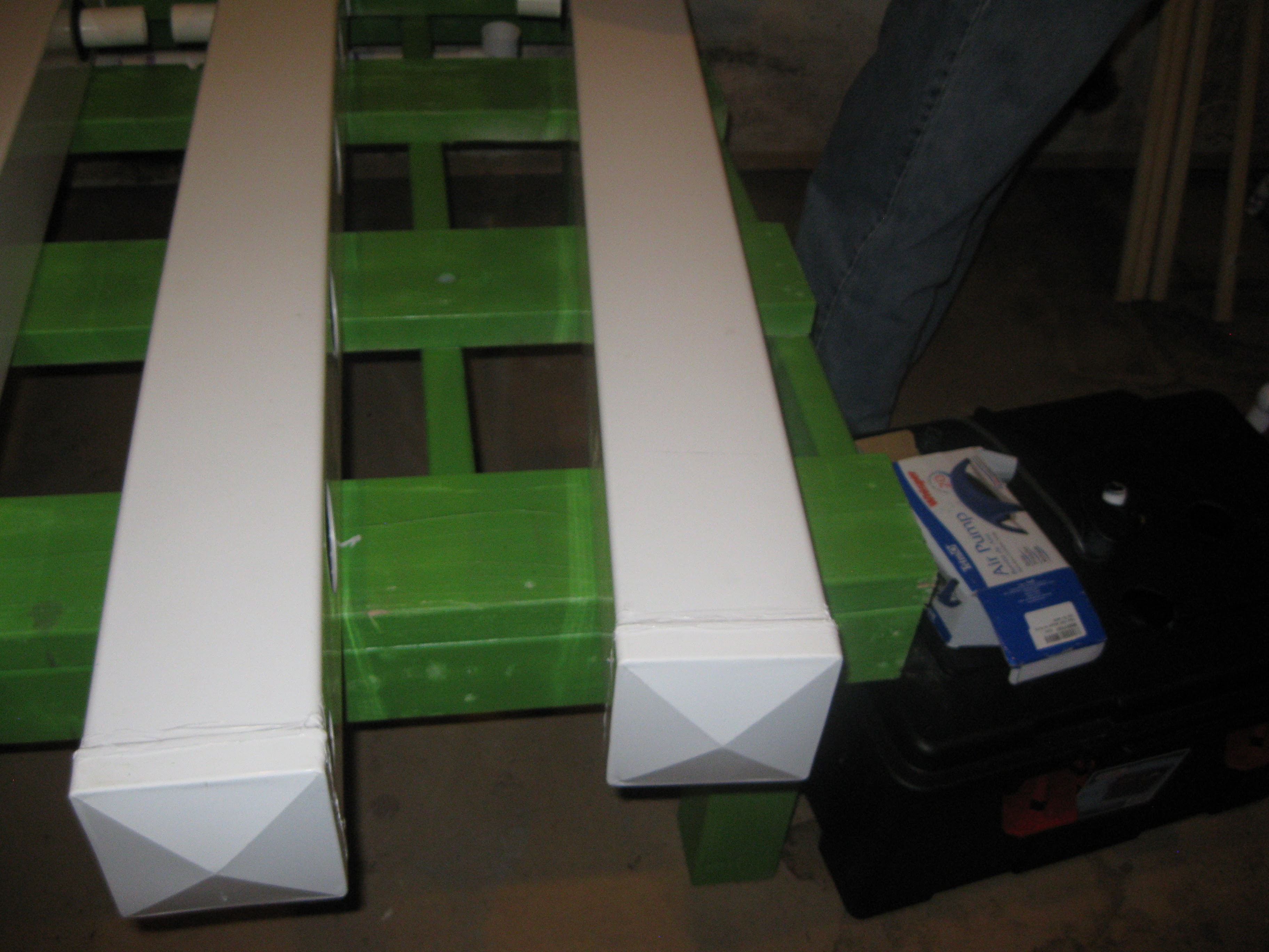
Moving along with the next post
![]()
First set of end caps sealed
![]()
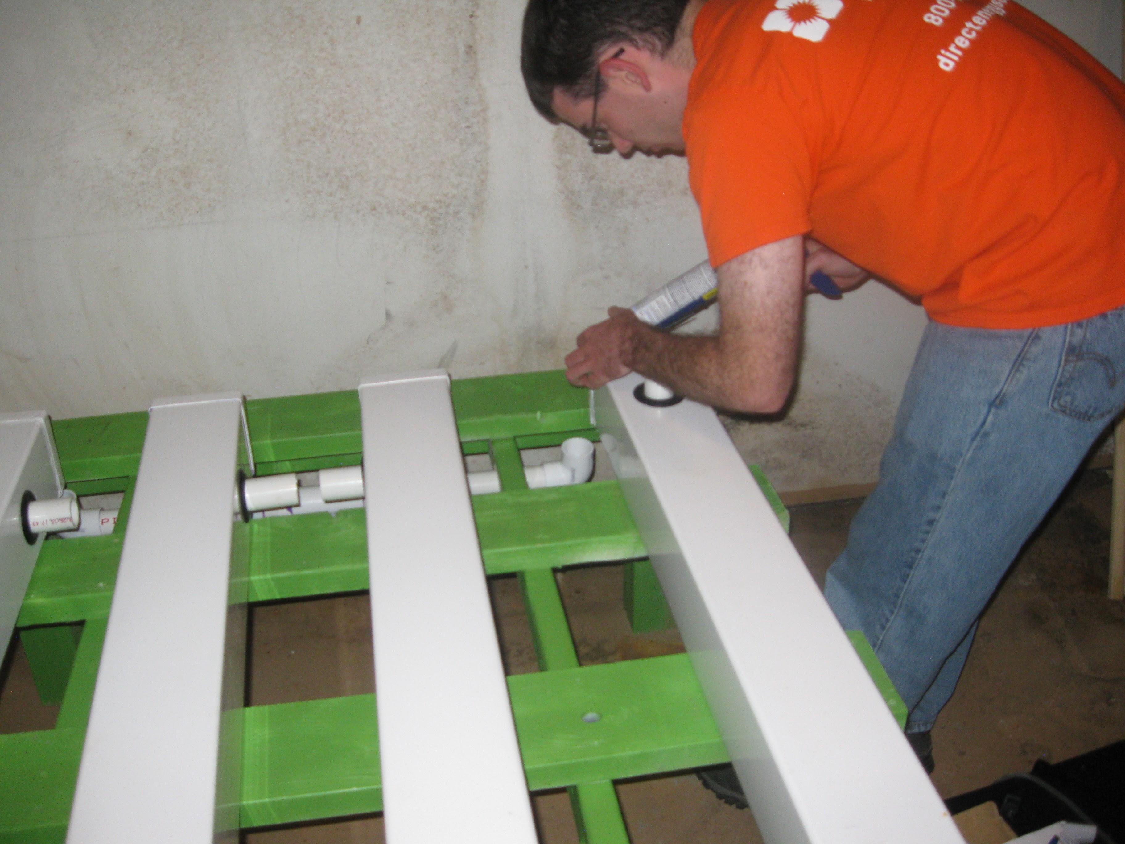
Doing the other sides
![]()
The silicone takes about 24 hours to cure, next update will be on testing water circulation and seals. I'm like to thank my friend and colleague Will Frankian for his continued support and helping hand with the assembly of this whole project!!! So stay tuned for more!!!
-
Plant Growth And Custom Grow Light Progress
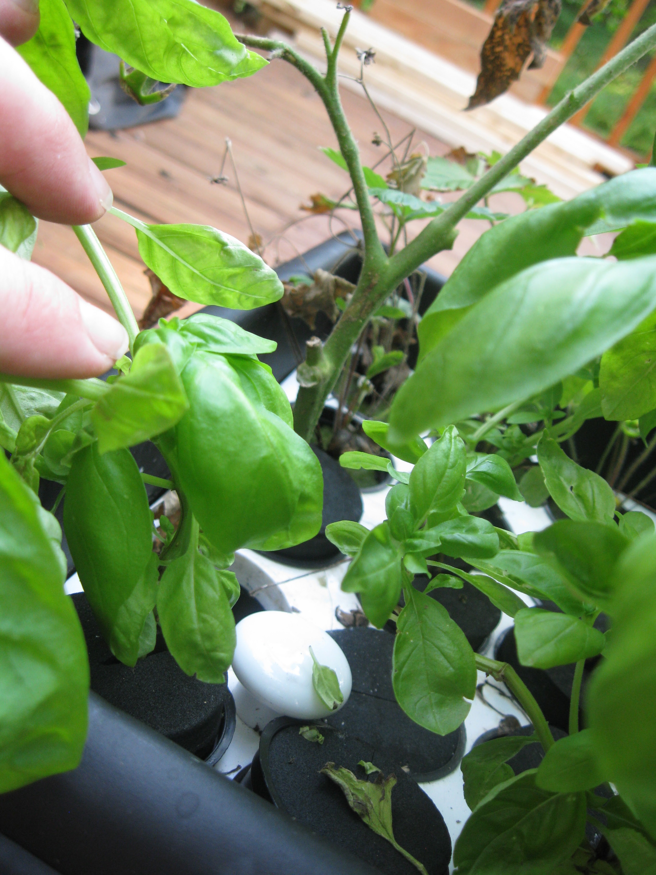
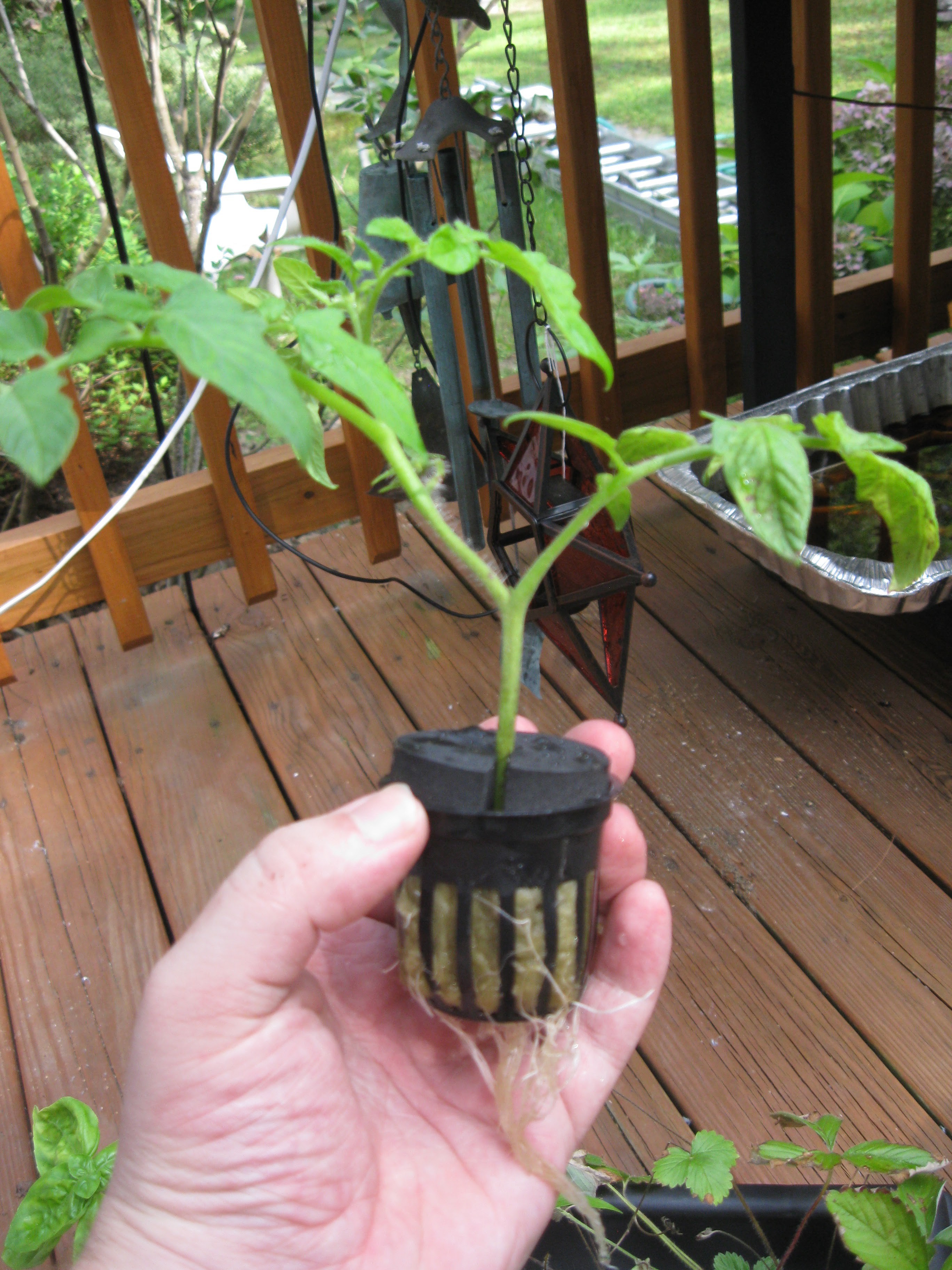
09/10/2015 at 04:22 • 0 commentsThe plants have been doing very well this past weekend. Most of the plants are ready for transplant. Today I just added more nutrients and took a look at all the plants. The strawberries are doing a lot better and now have roots!
![]()
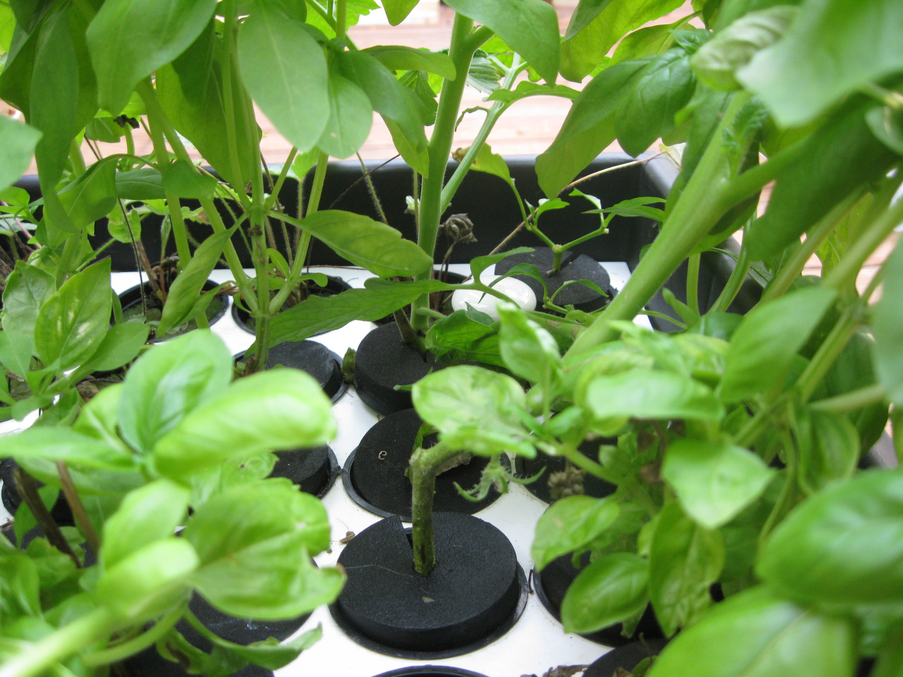
Closer look at the plants in the cloner
![]()
Another view of the plants in the cloner
![]()
![]()
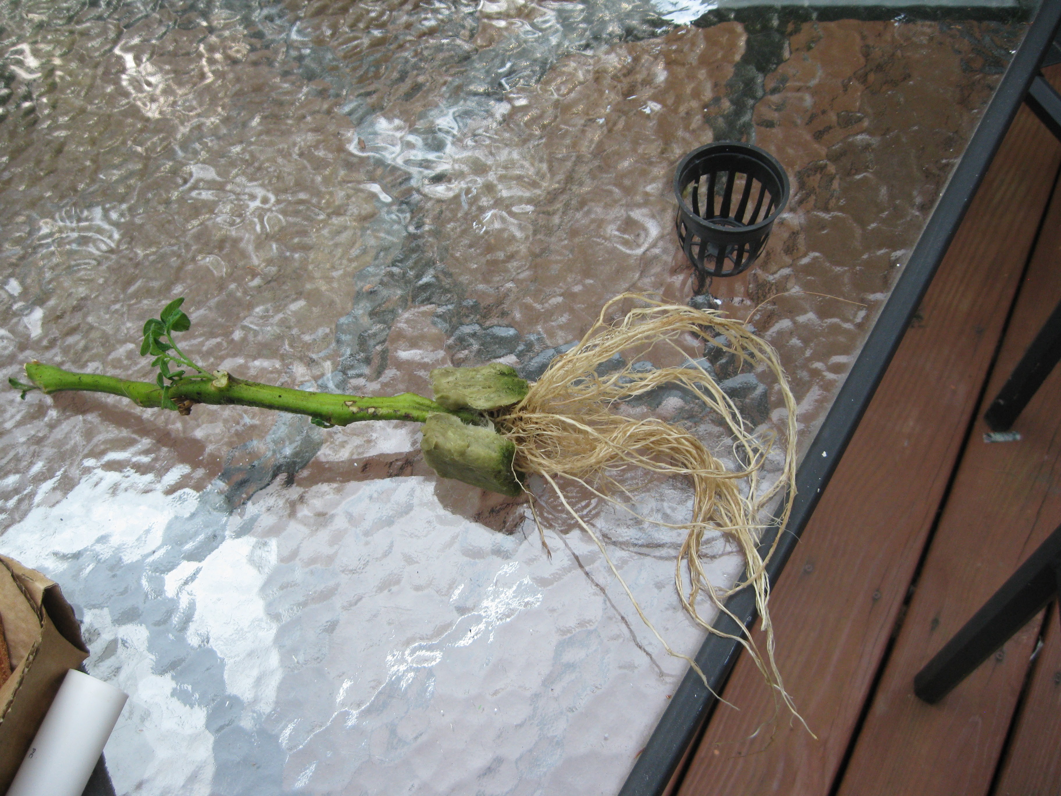
I also decided to create another tomato plant again from the same plant that I made two out of the existing three from. I thought the potted plant was dying the last time I made a cutting from it, well this week it grew new leaves so instead of watering it I took it out of the dirt and cleaned the roots. After I thoroughly cleaned the roots I put it into the cloner so it can get back to health before transplanting. So far this plant has made 3 plants, pretty good recycling of the potted plant from walmart!
![]()
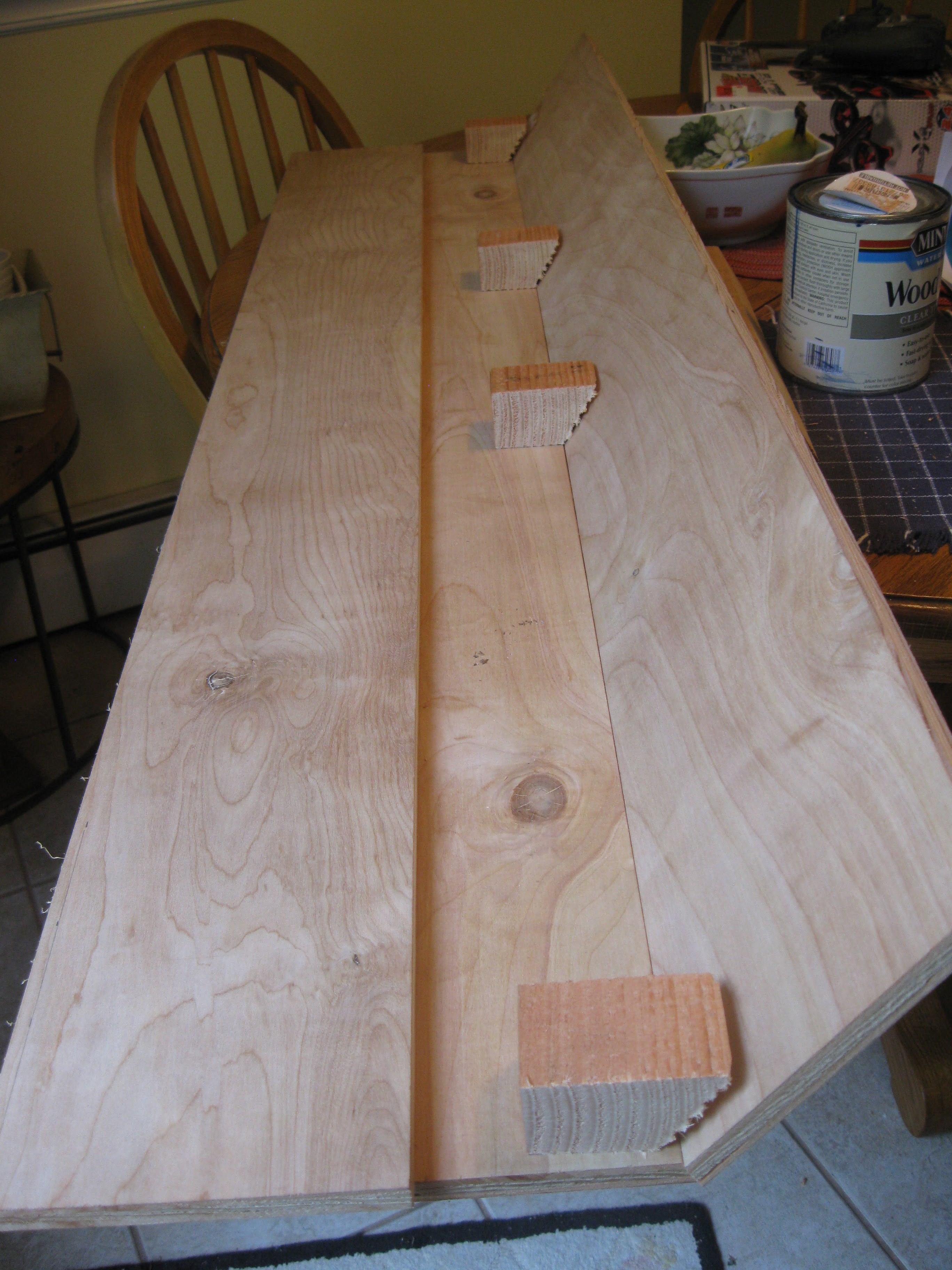
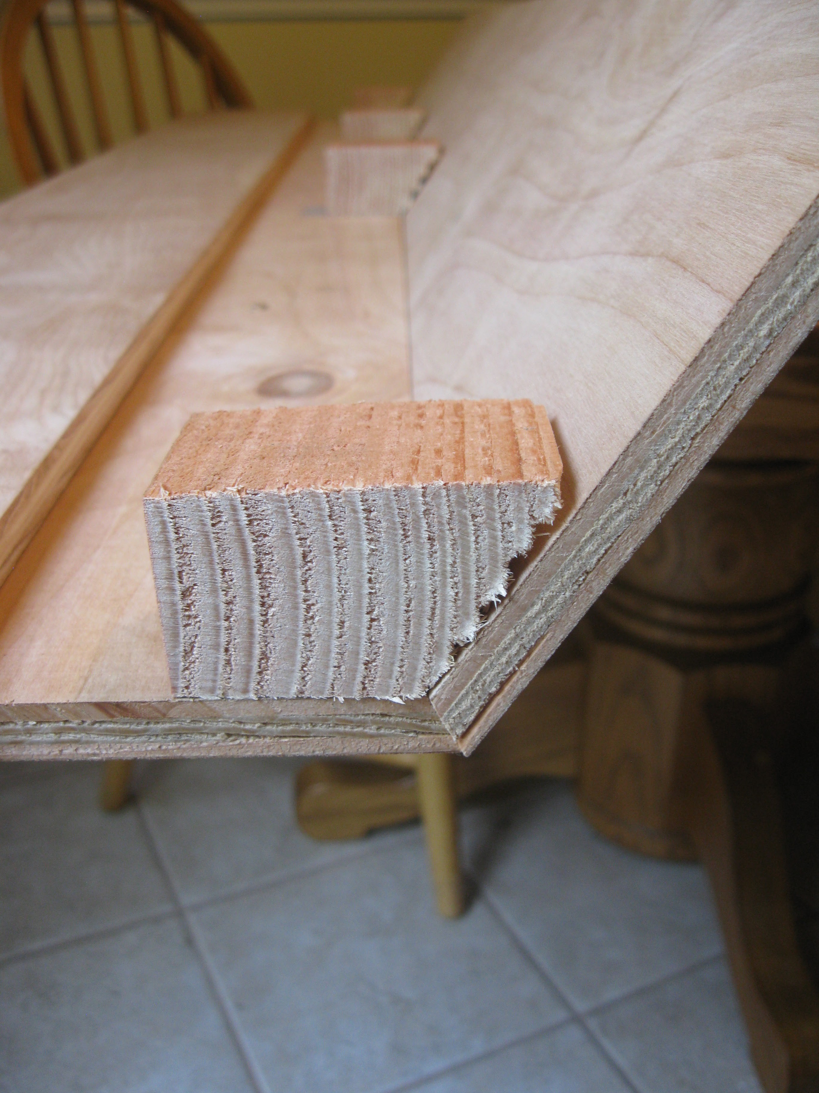
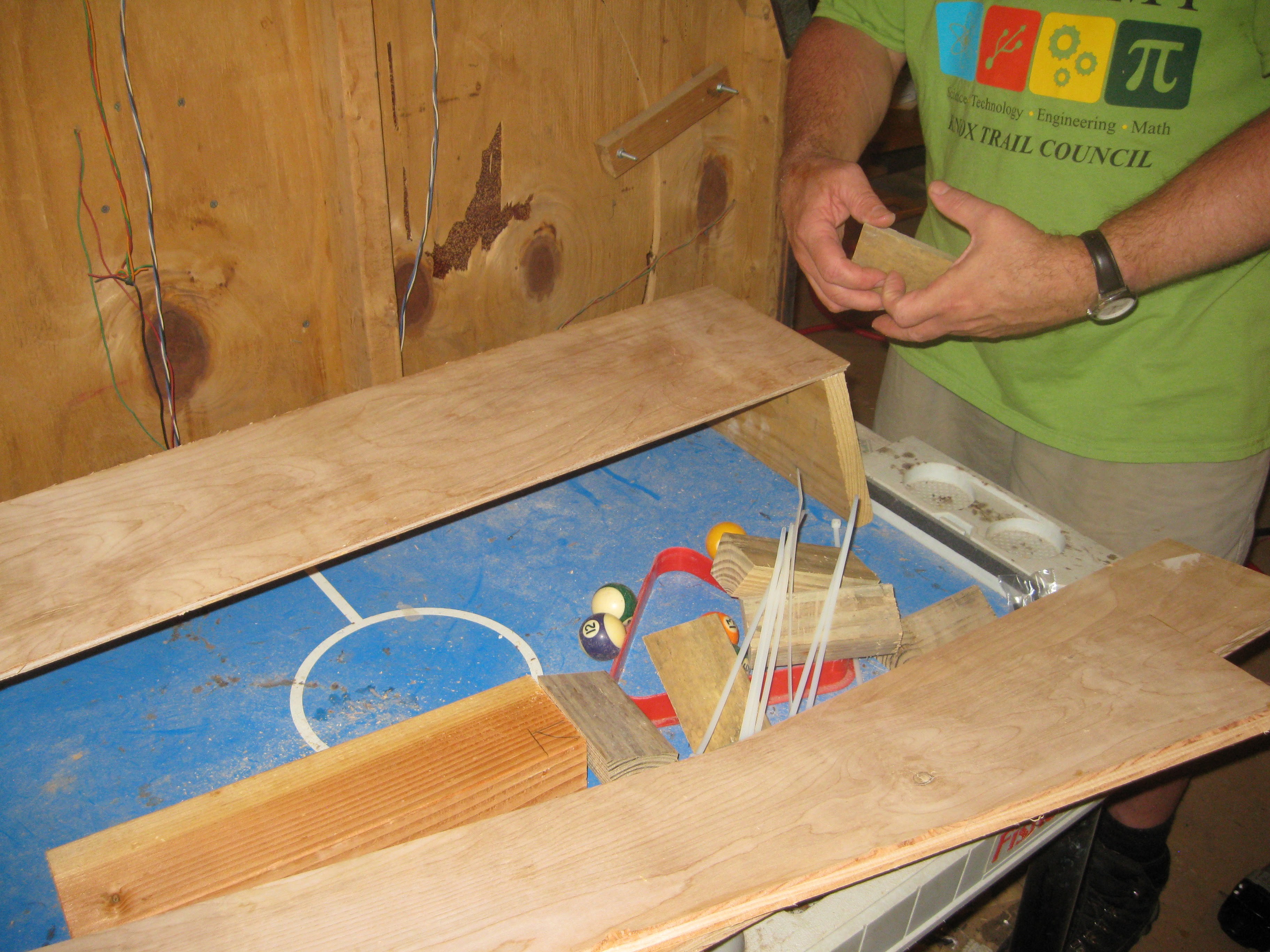
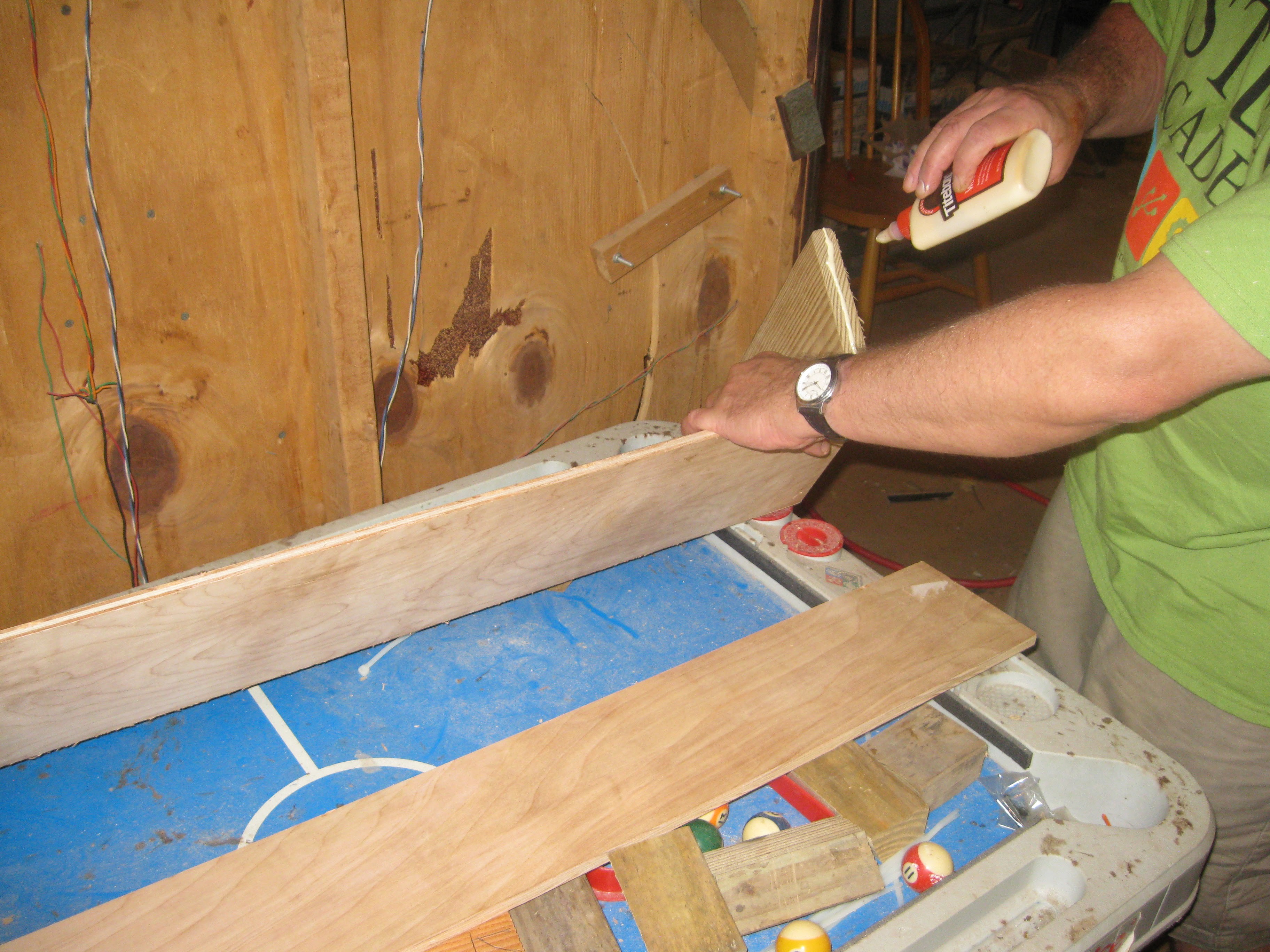
I also got a lot done on the custom grow light and will be updating its dedicated project page as well. I got the light frame finally assembled, after a few hangups. There were some issues with the accuracy of the angled bevels on the different piece of the frame. THe original idea was to create cleets and assemble the frame by gluing and nailing it along the seams while the cleets screwed in place held it together while the glue set. Due the differences in the angles on all the pieces assembling the light frame/casing this way was problematic and very difficult. At the suggest of my dad we recut all the bevels this time being more consistent with the angle and using a fresh sharp table saw blade. Instead of using cleets we fashioned ends for the frame out of decking board and using the table saw and mitre saw. In the end the piece were glued and nailed together with a nail gun, instead attaching the ends first and using them as the support instead of cleets.
original cut and beveled pieces with the cleets
![]()
Another view
![]()
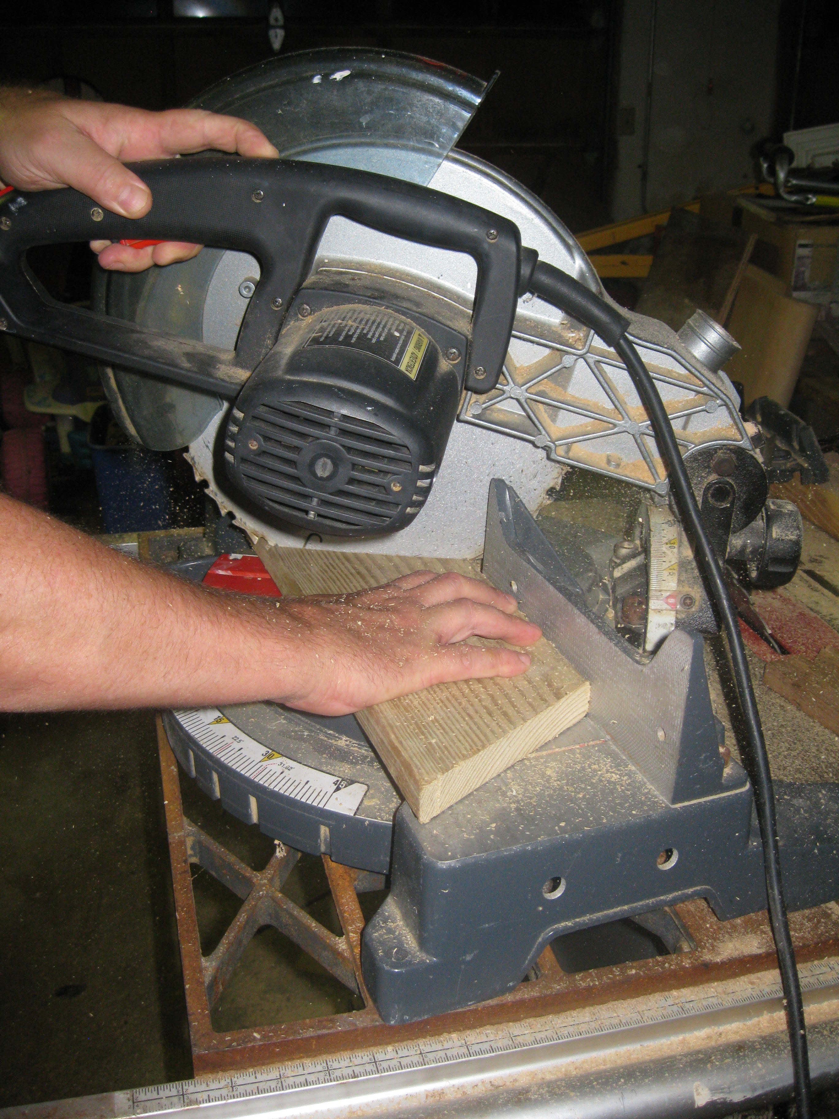
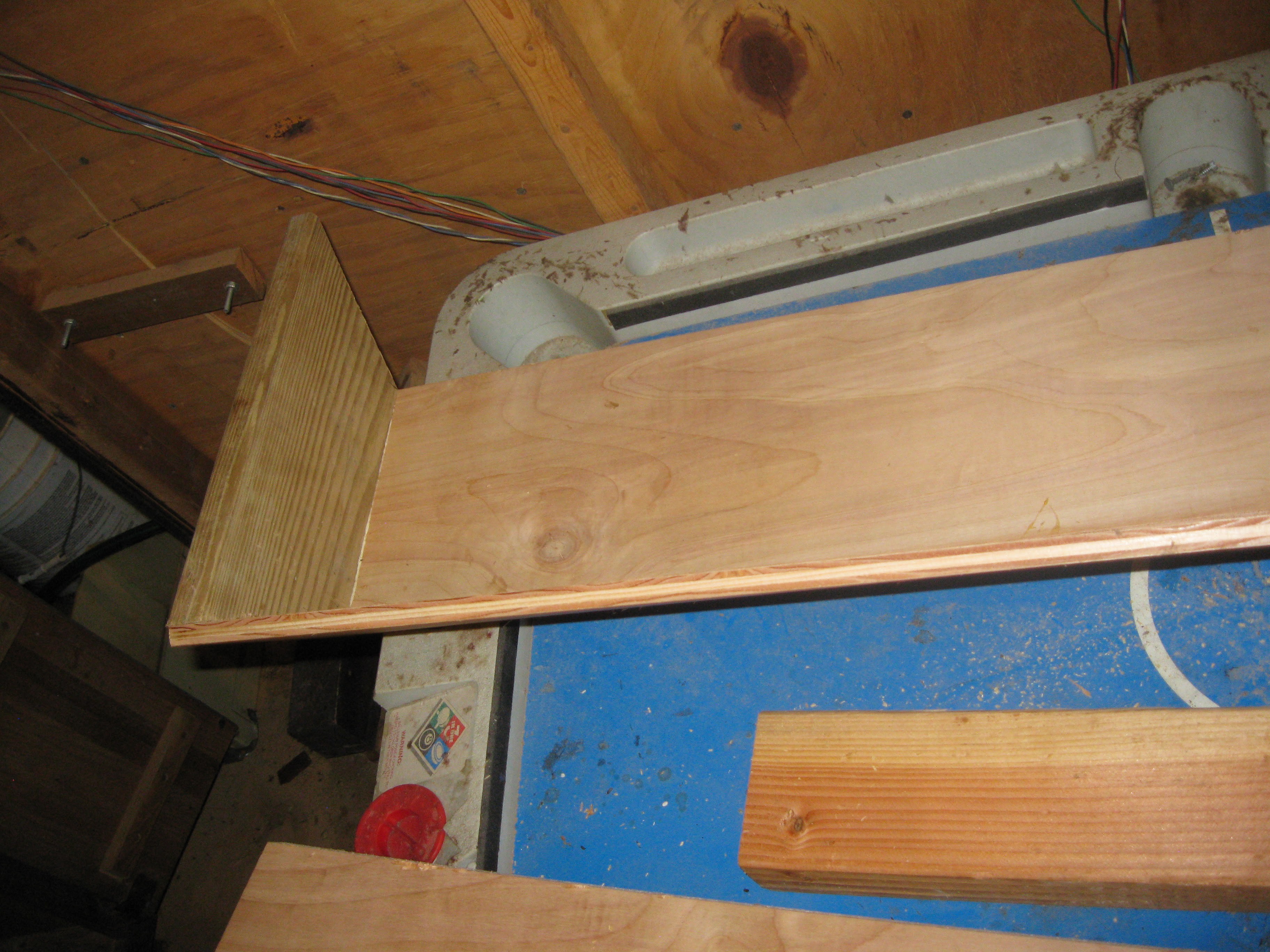
Beginnings of an end for the light made of deck board.
![]()
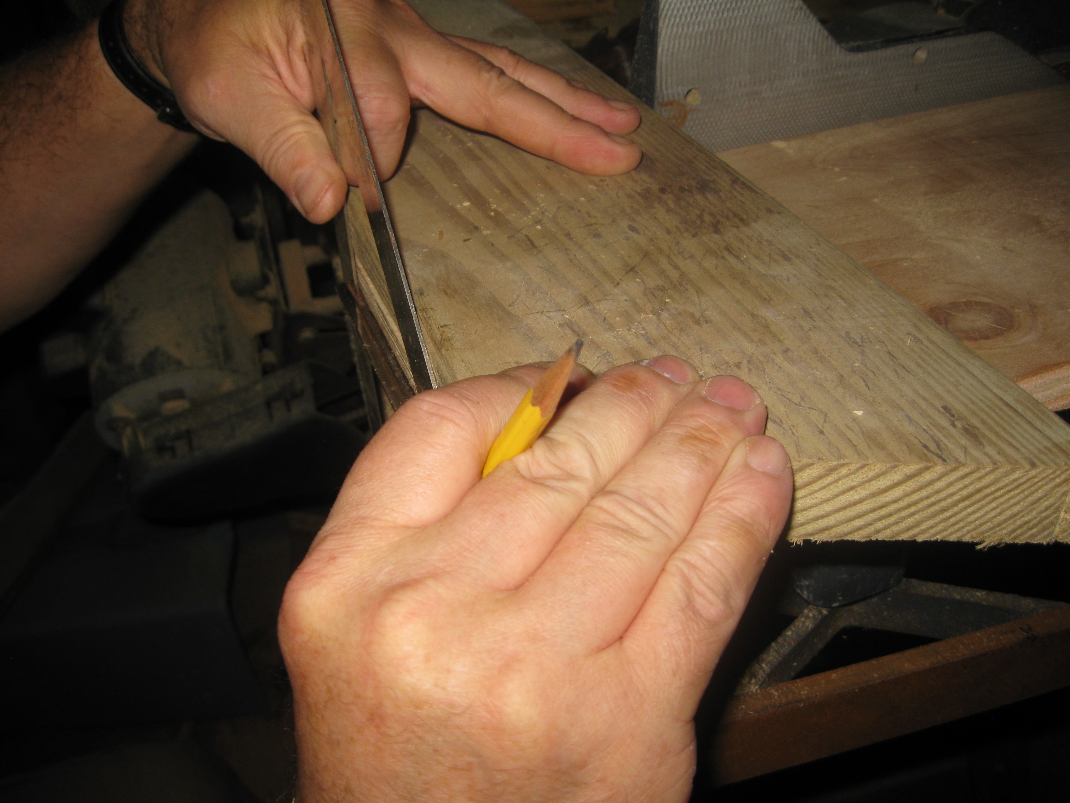
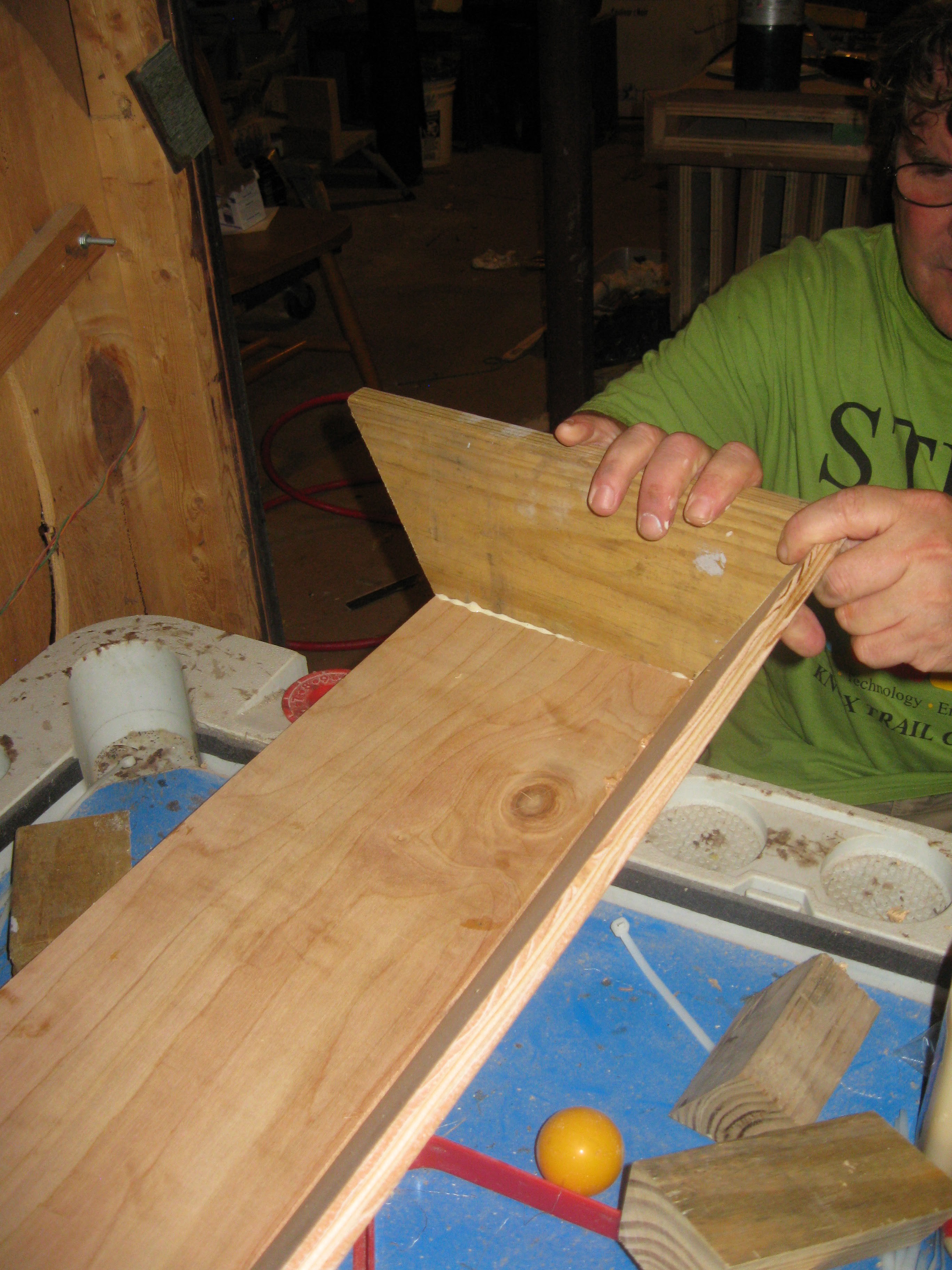
One end being finished with the last cut.
![]()
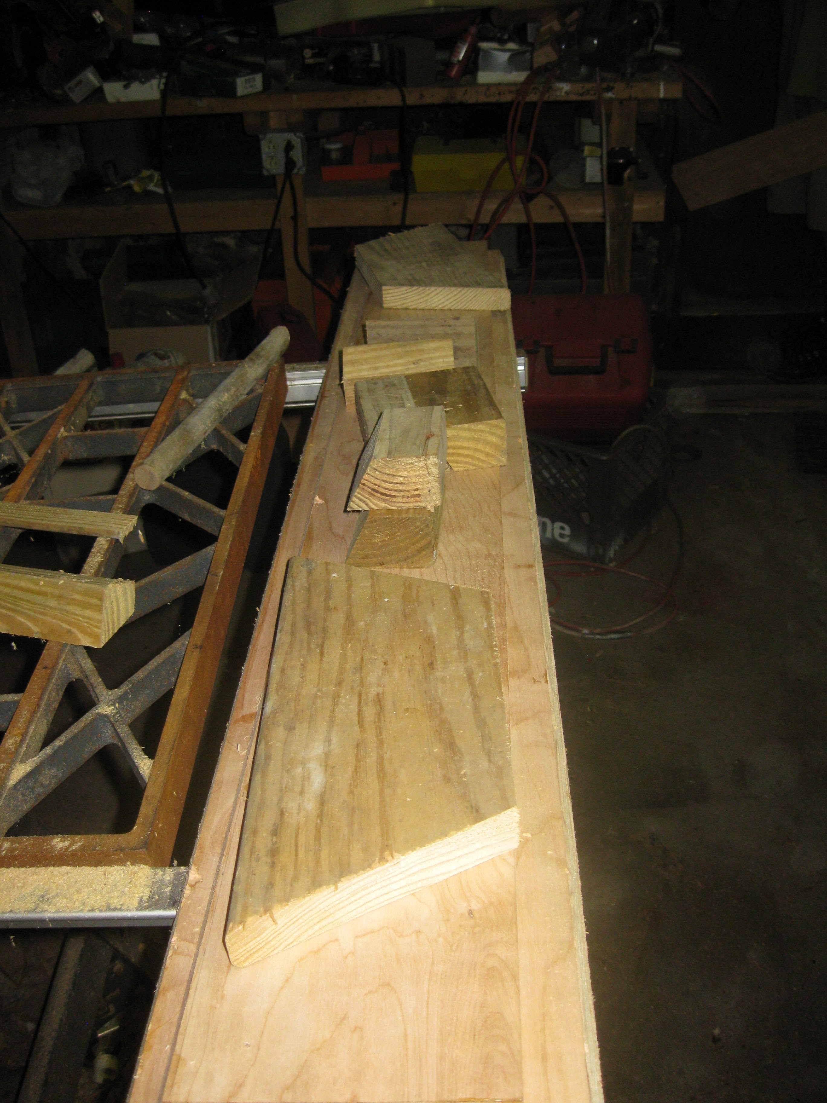
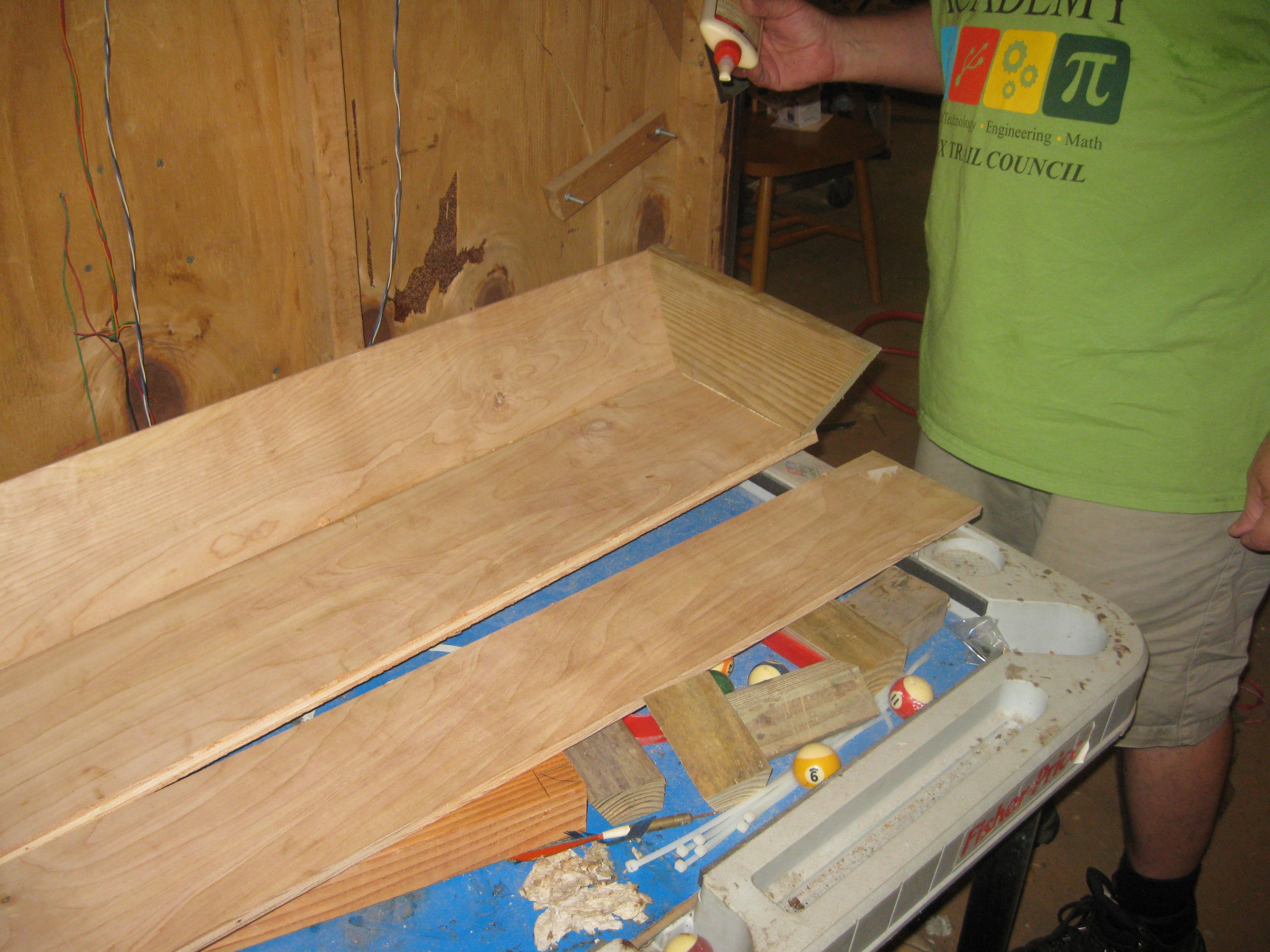
Finished newly cut pieces with more consistent bevel angles.
![]()
Gluing and nailing the light frame/casing together, here starting with one of the ends glued in place, new cleets were made but not for securing the parts together but rather for lining up the beveled joints.
![]()
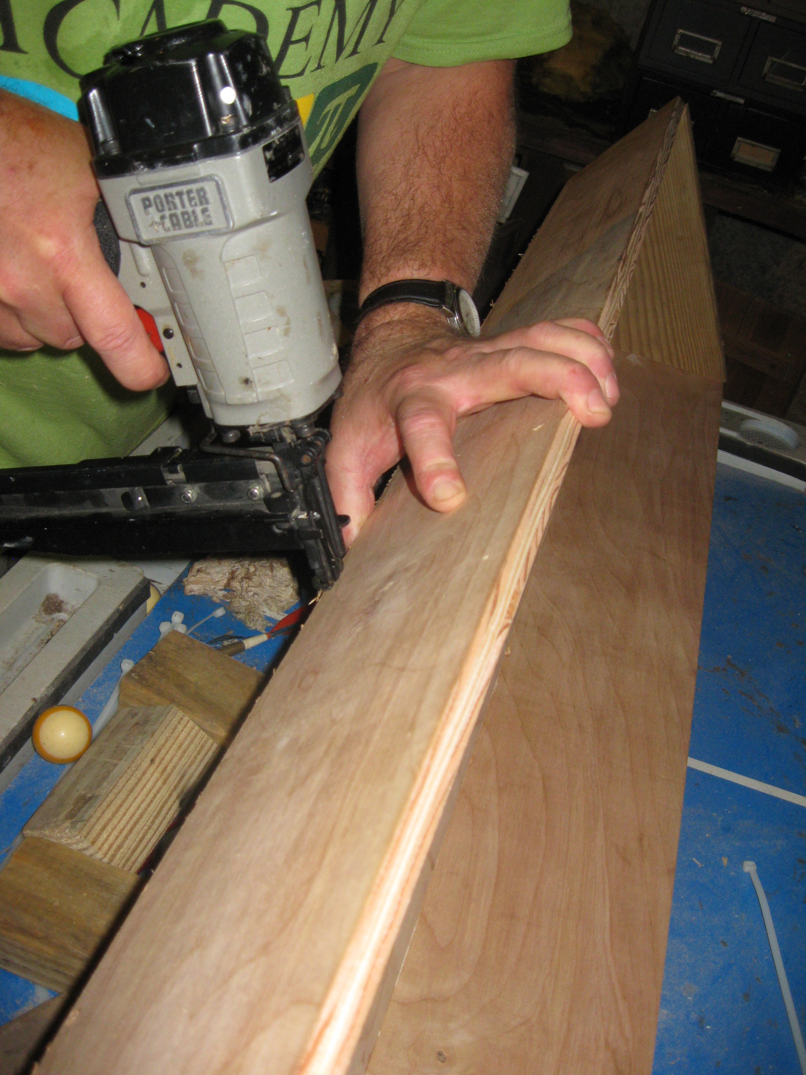
With both ends glued and nailed into place with 2" nails the first side was added. 2" nails going into the deck board ends and 1 inch nails allong the beveled seam with glue inside.
![]()
Adjusting the other end before final nailing
![]()
![]()
Doing the other side
![]()
![]()
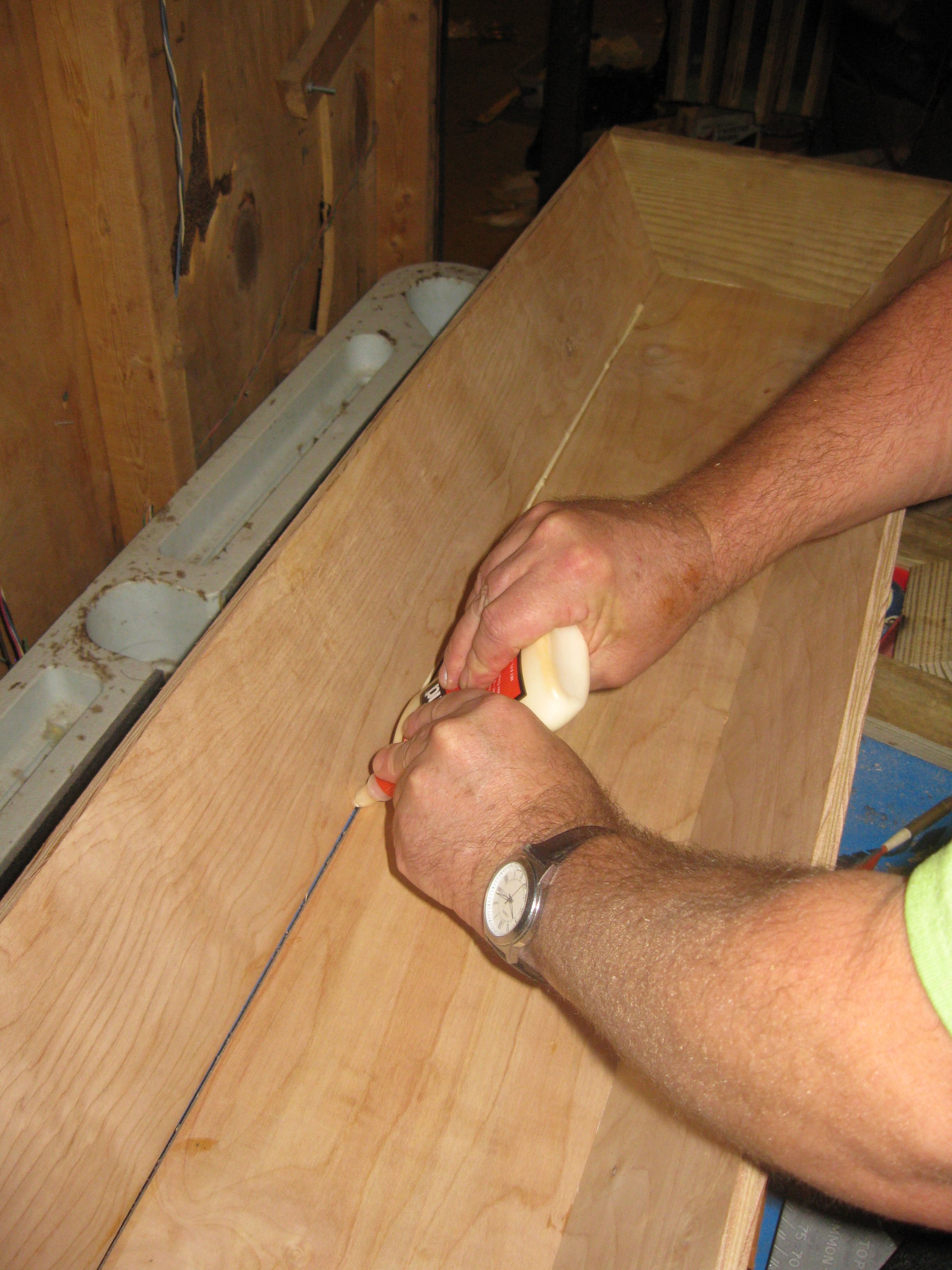
Adding glue to the other side's seam before nailing it all together along the way.
![]()
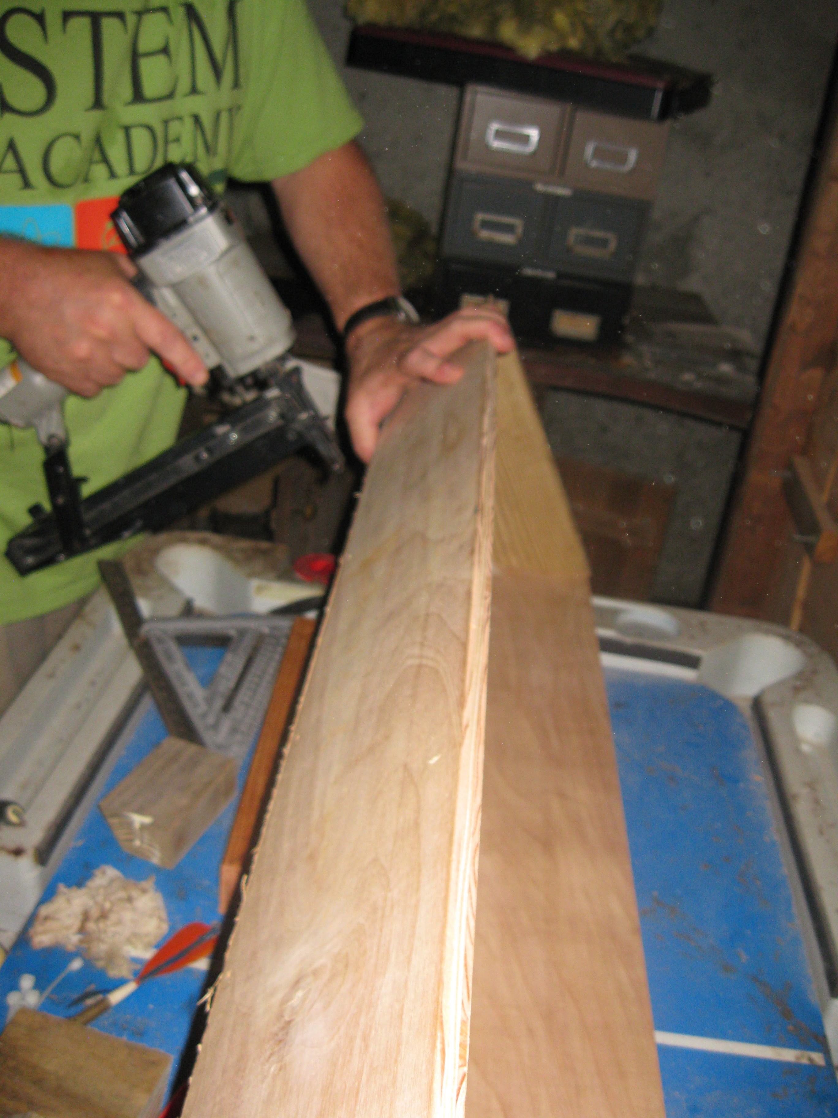
Nailing of the seams:
![]()
![]()
Finished assembly
![]()
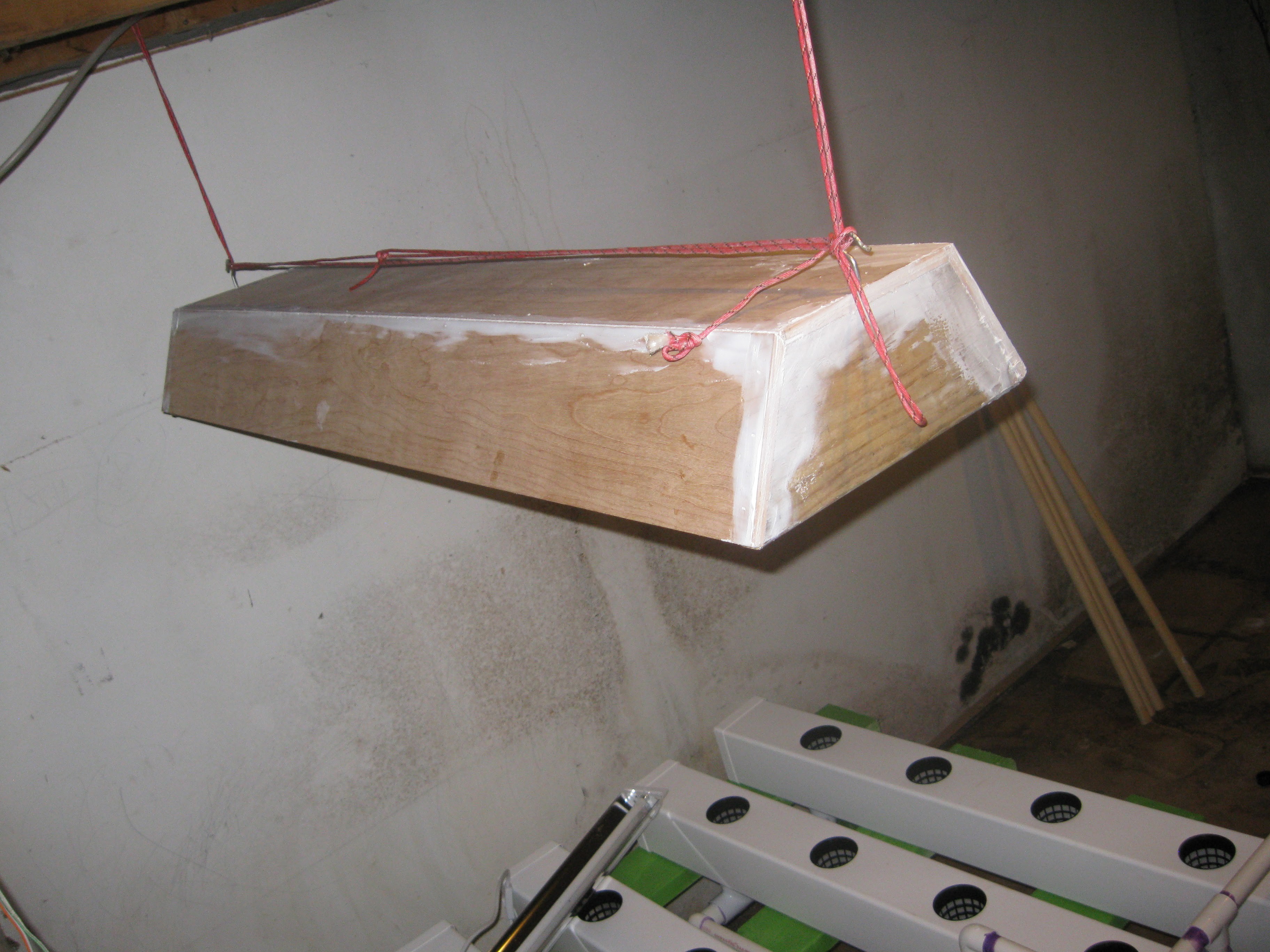
For hanging the light will hang from the ceiling via chains, the chain will be attached using hooks bolted into either end of the light.
![]()
![]()
After the assembly and addition of the hooks I decided to work on smoothing the surface before painting. Despite our best efforts at trying to cut everything with consistent angles there were still some gaps. I decided to fill the gaps with caulking and to sand it down before painting. I used caulking to fill in the gaps in the seams and I filled in the countsink holes the nailgun left over every nail.
![]()
Getting ready to add caulking to the other side's seam after the first one is finished
![]()
Caulking added to second seam before smoothing, its messy but i prefer to smooth it all into the cracks by hand with my fingers, helps to fill the gaps tightly.
![]()
I did the smaller seams on the ends too, the idea being that the whole thing will look like one piece after painting. Painting isn't necessary but I have this idea of making everything pastel colors to make it more fun to look at.
![]()
![]()
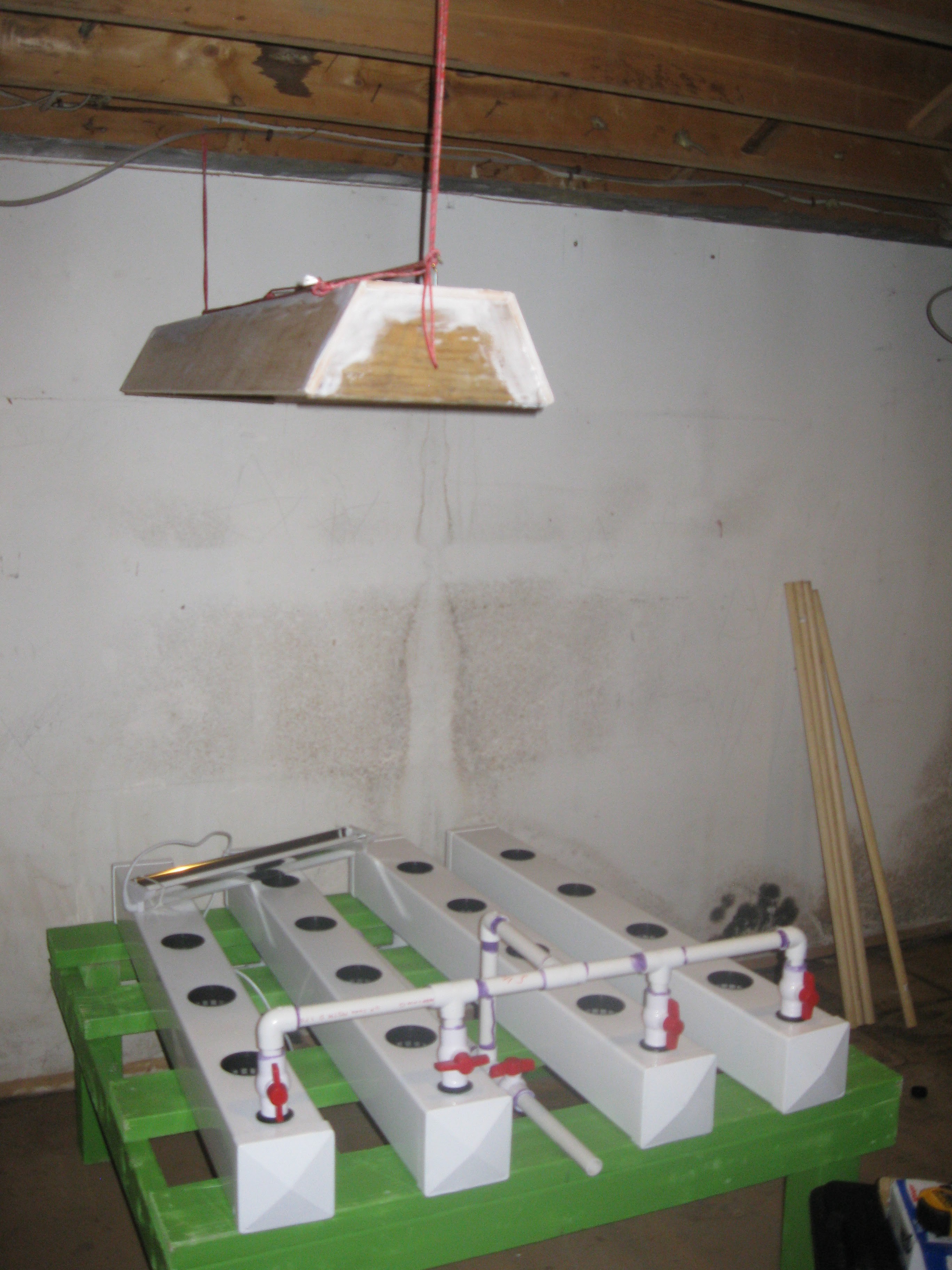
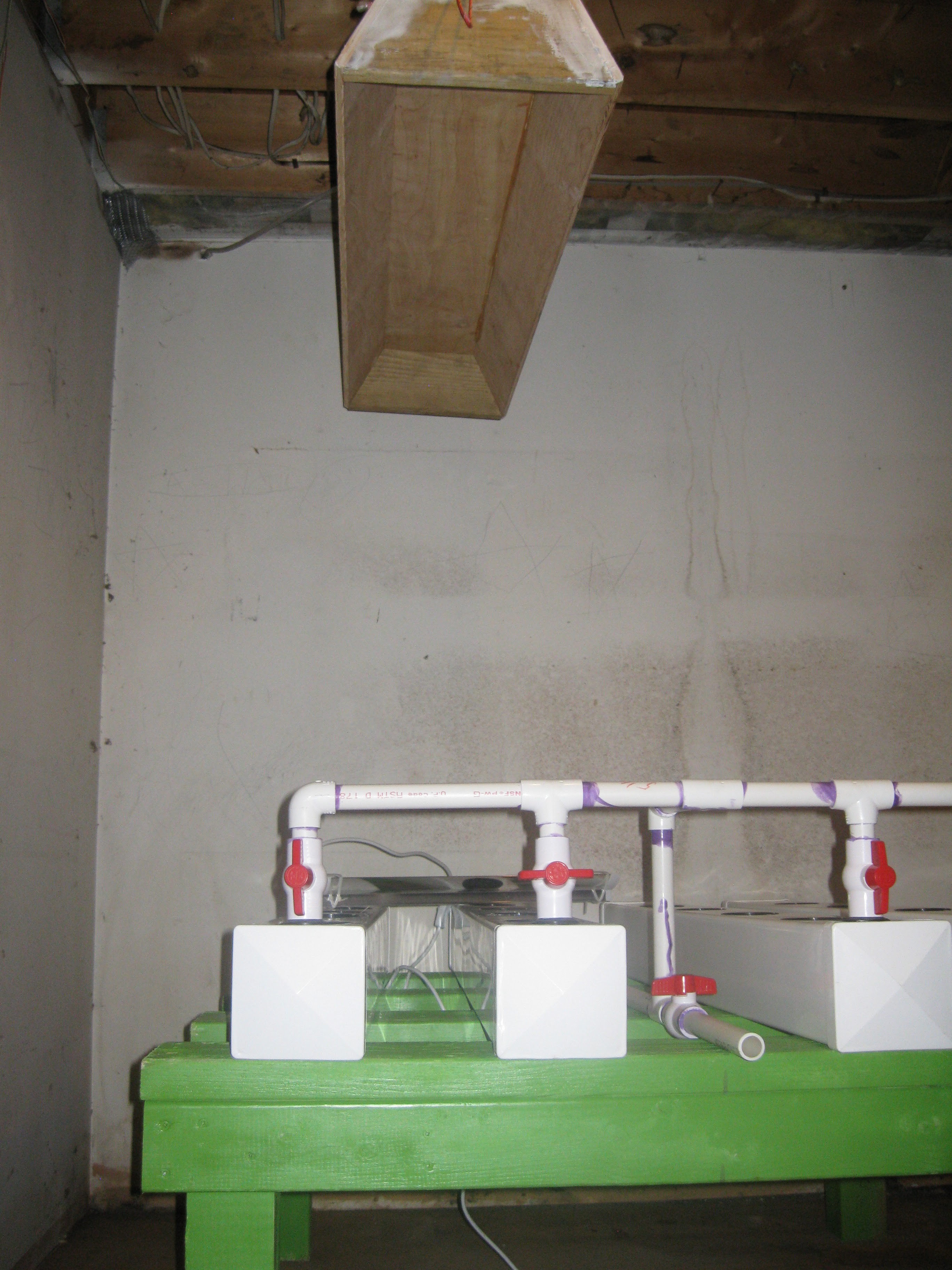
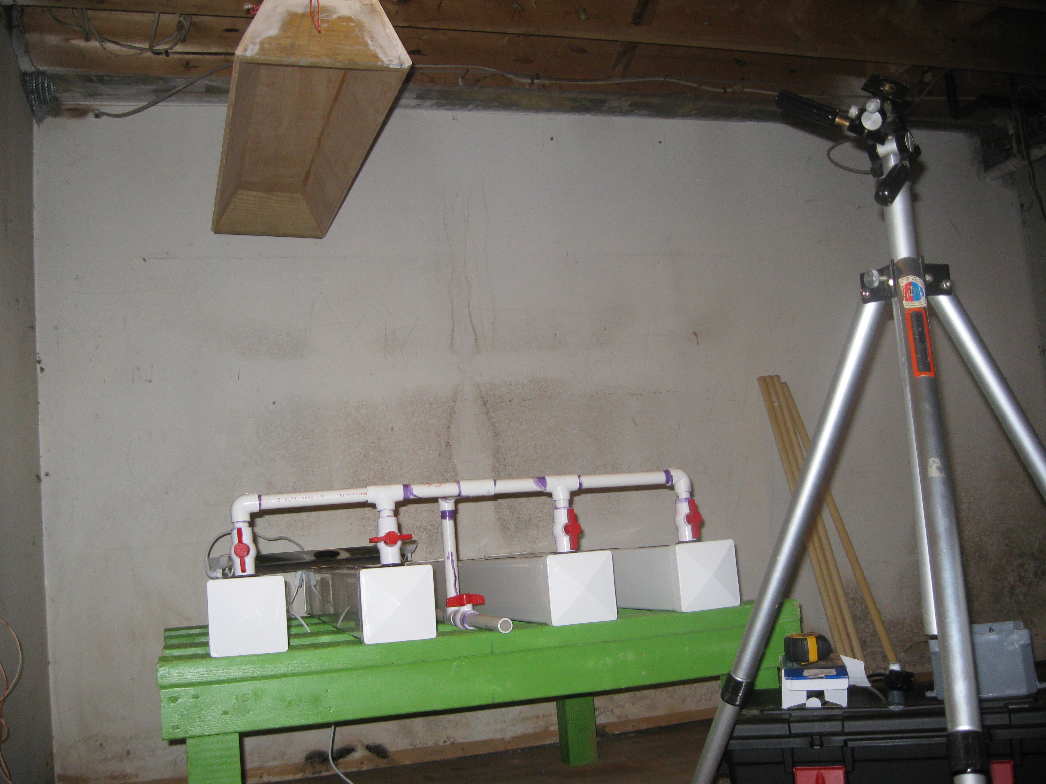
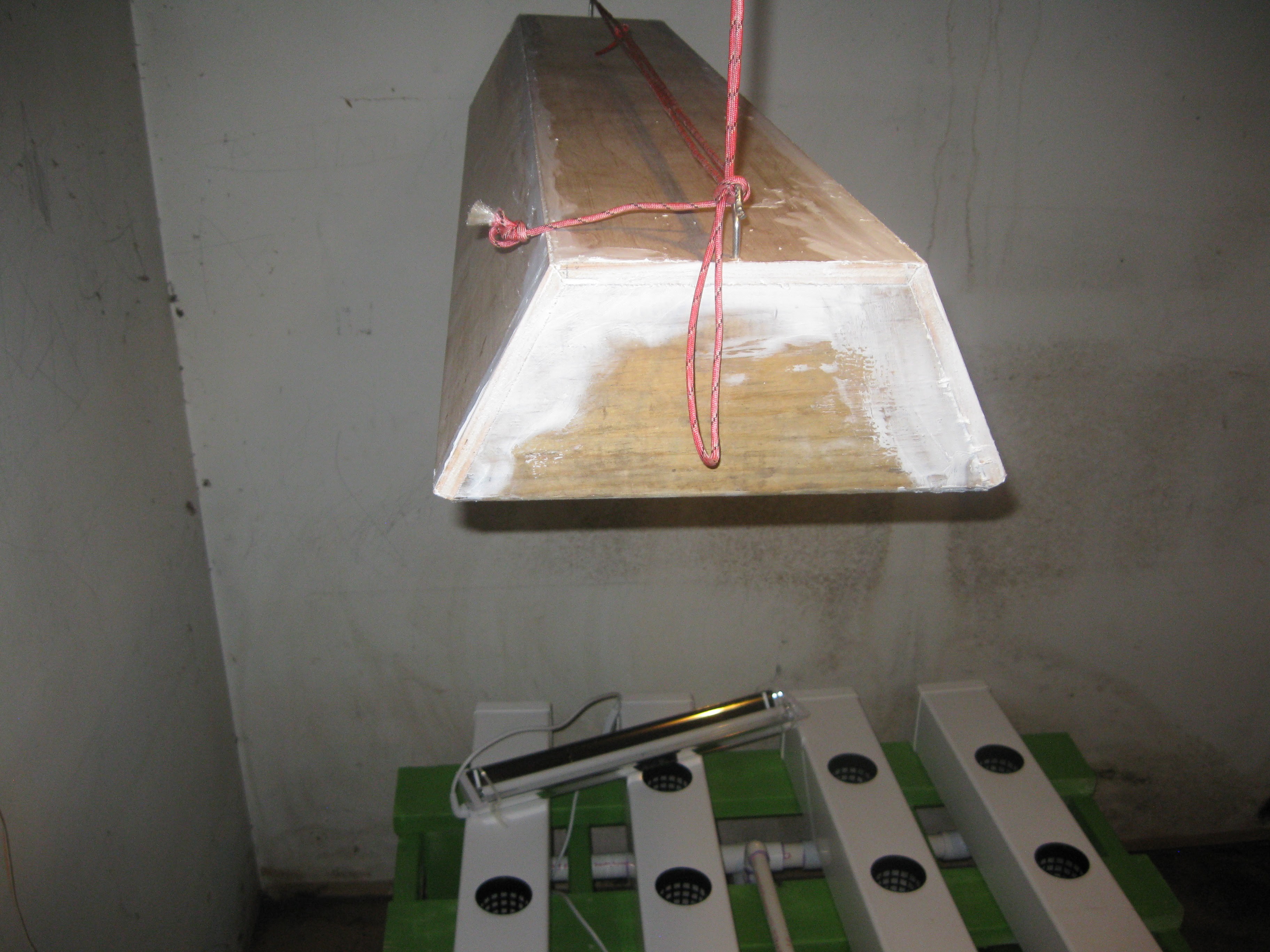
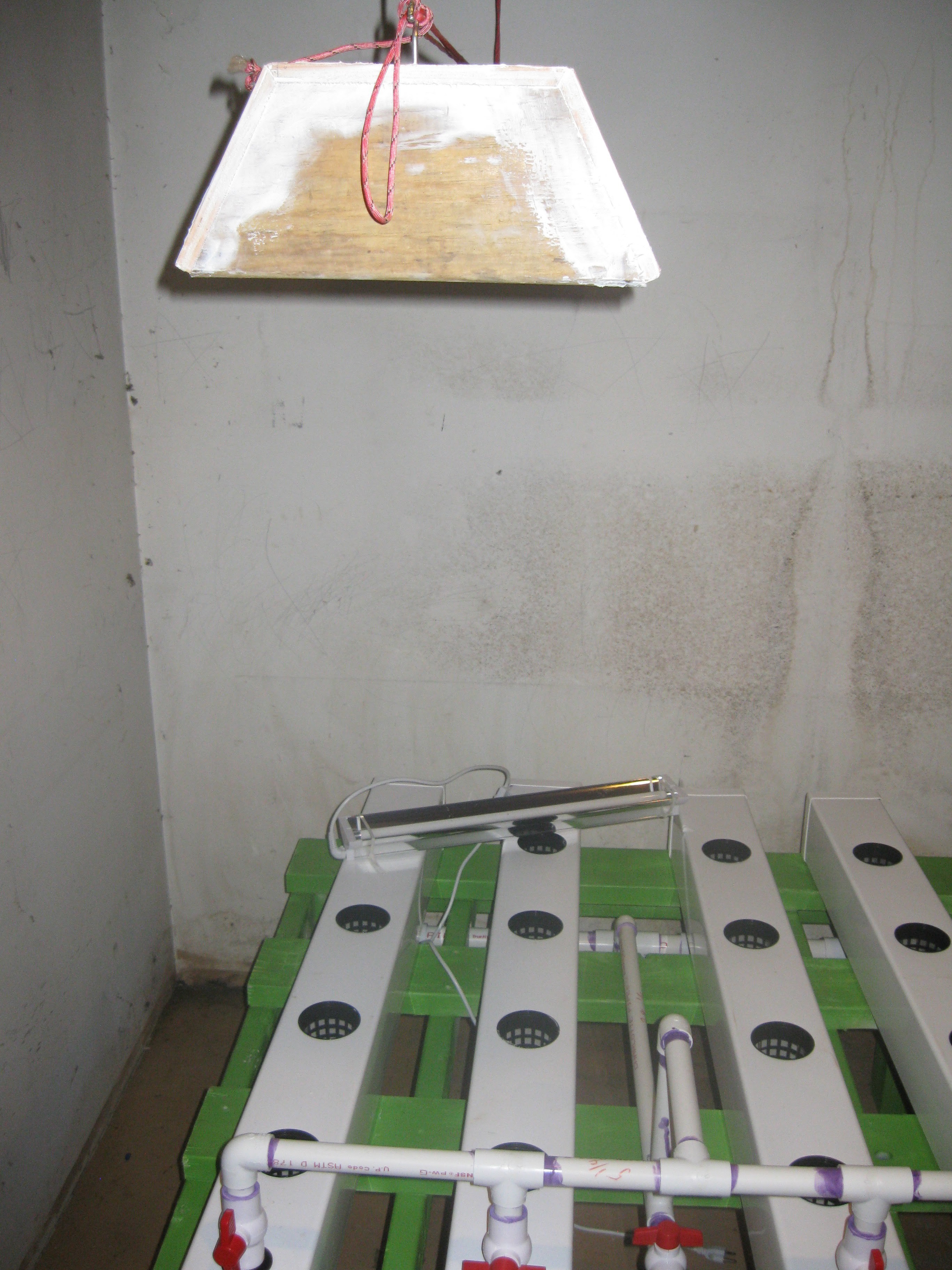
After I gave some time for the caulking to air dry for a bit I couldn't help myself and decided to do a mockup and hang the light above the NFT unit. I simple added some screws to the rafters and tied it up with paracord. In actuallity it will be held in place with chains to make adjusting its height easy, who knows down the light I mihgt have an automated pulley system to drive it up and down!
![]()
![]()
![]()
![]()
![]()
![]()
![]()
Stay tuned for more updates!!!!! I'm trying to keep the posts up with all the work I'm getting done, more soon!
-
Move to the basement and Manifold Gluing
09/10/2015 at 02:21 • 0 commentsSo this pas week I got a lot of work done on the project. Also the plants are doing wonderful, they sort of prompted the acceleration of the project and all the work that got done. The NFT grow system was moved into my basement after a bit of cleanup. The input and drain manifolds were glued together and installed into the unit permanently.
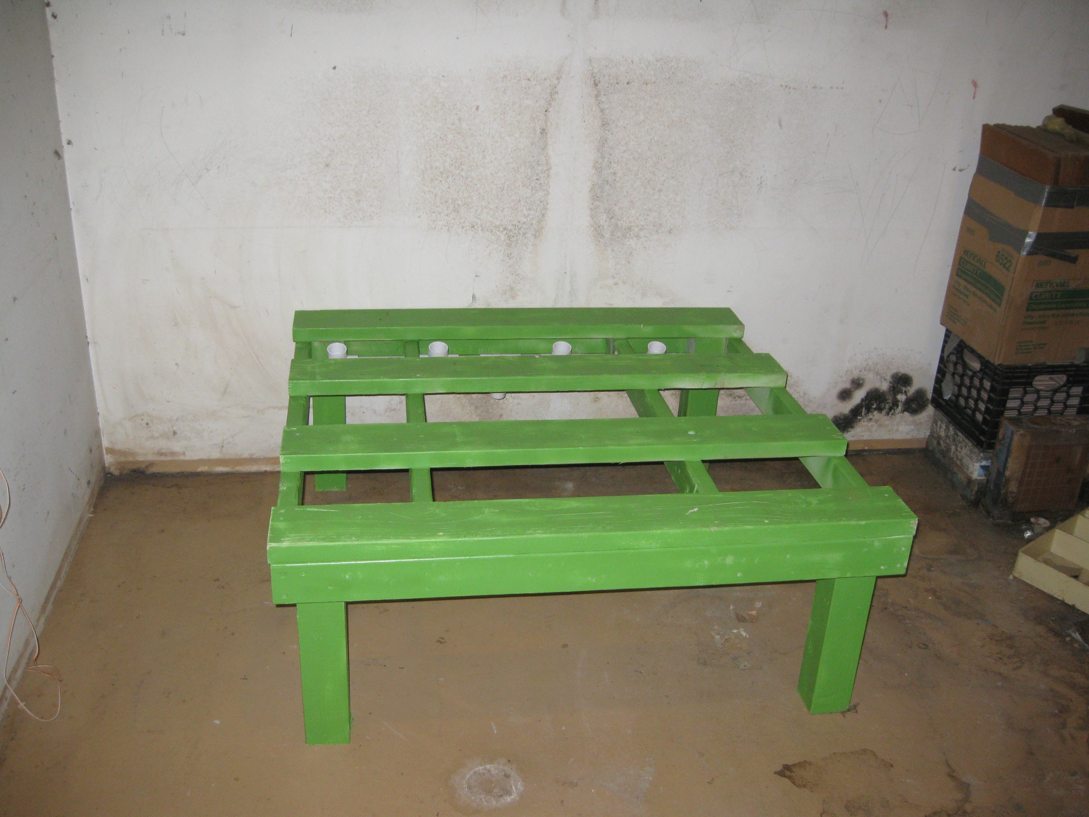
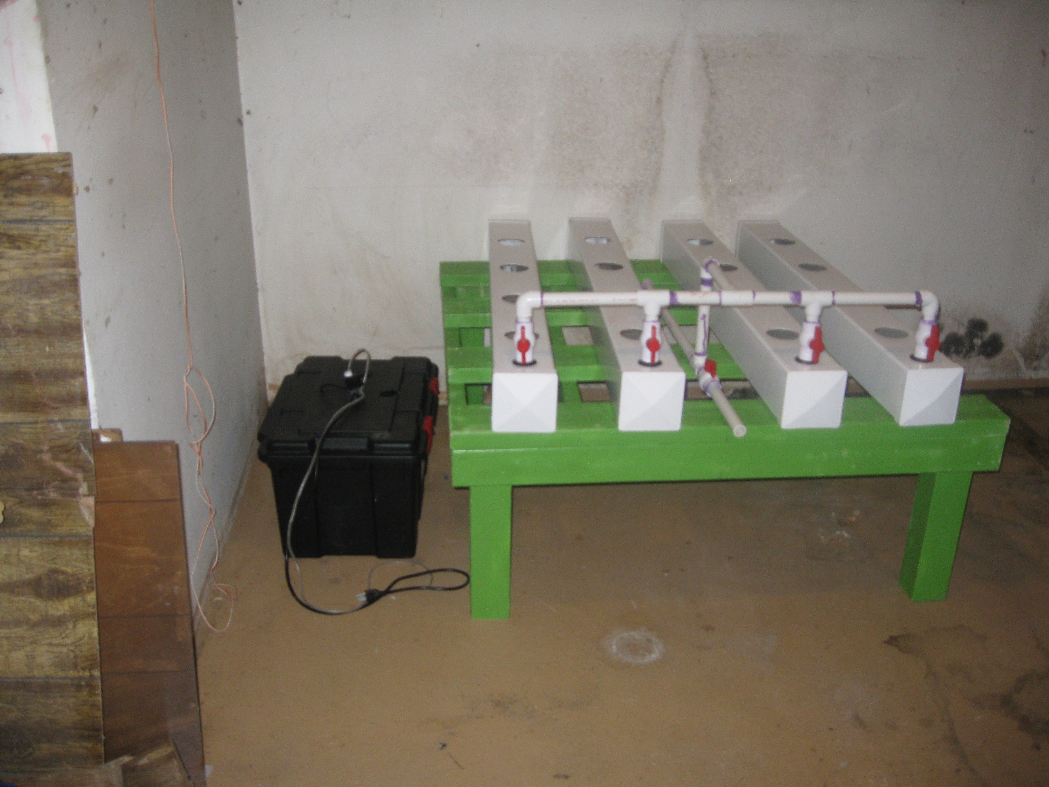
The move was rather simple, there is a place in my basement where across from the furnace, I cleared out junk and placed the NFT system in there. The space I placed it in happens to be the right size for the setup, the plan is to build another unit thats a bit taller to be placed next to it. Take a look:
![]()
I later cleared the pile of ceramic tile and junk out of there. A second frame of the same design but with 23" legs (I did that for all you superstitious folks) painted blue will be placed in the space next to the green one pictured here. Moving the unit was fairly simple, the entire thing came apart very easily, like I hoped it would. The rows (fence posts) are easily removed once the input manifold is simply pulled off. The rows pull off the drain manifold keeping the 1 1/4 " pipe used to mat them to the manifold tight inside the uniseal. These pipe piece were not glued to the manifold, this is so that the rows can be removed if the garden needs to be dismantled or cleaned.
Dry press fit the drain manifold in place, Input manifold in pieces.
![]()
Input manifold dry fit together.
![]()
Drain manifold gluing process, the manifold is assembled within the frame, it gets permanently installed this way but it adds rigidity to the system and serves to lock the fence post grow rows in place.
![]()
One side assembled
![]()
Midway assembling second side of drain manifold.
![]()
Another view
![]()
Second half of manifold completely assembled.
![]()
Another view of the completed manifold
![]()
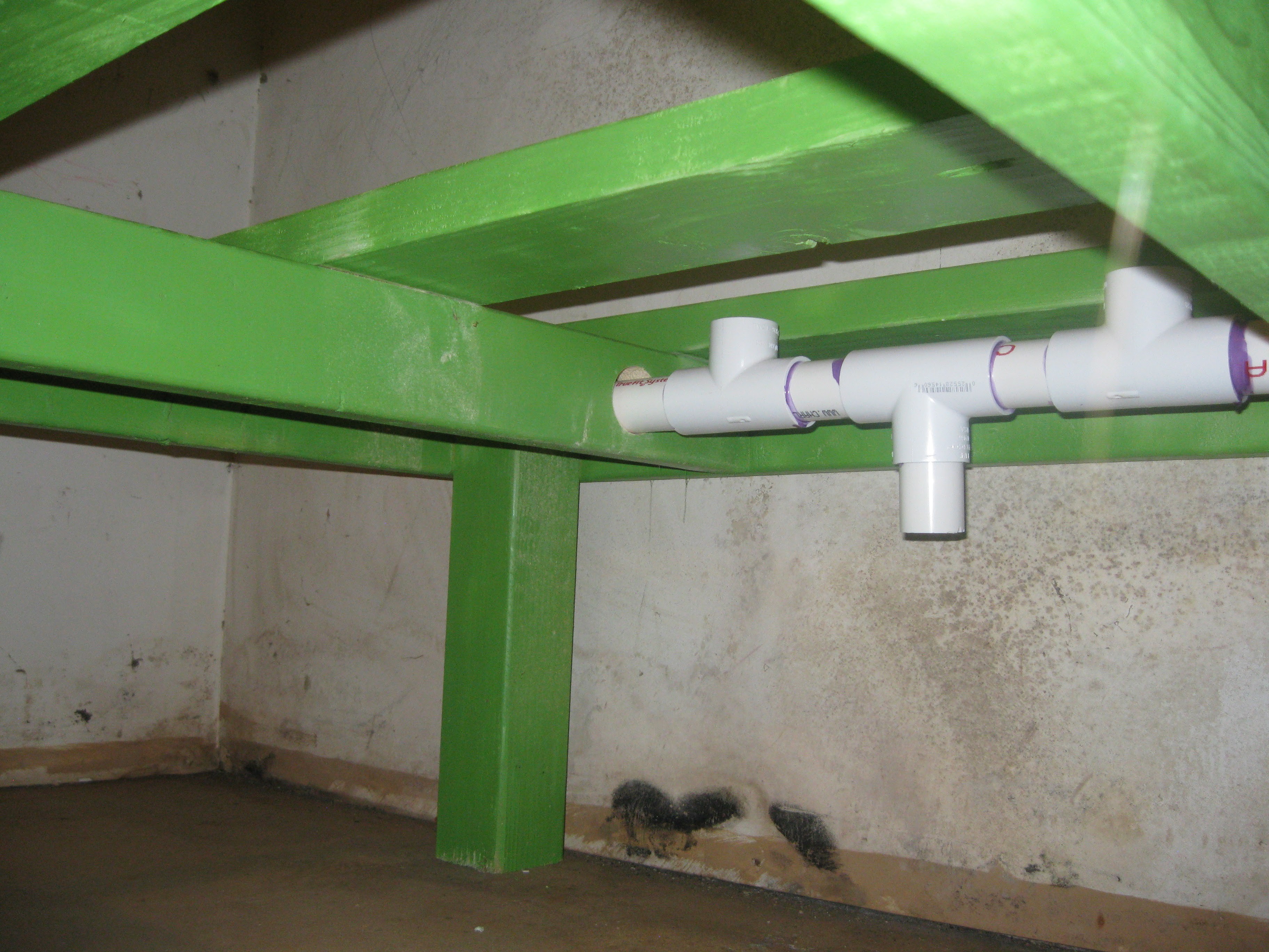
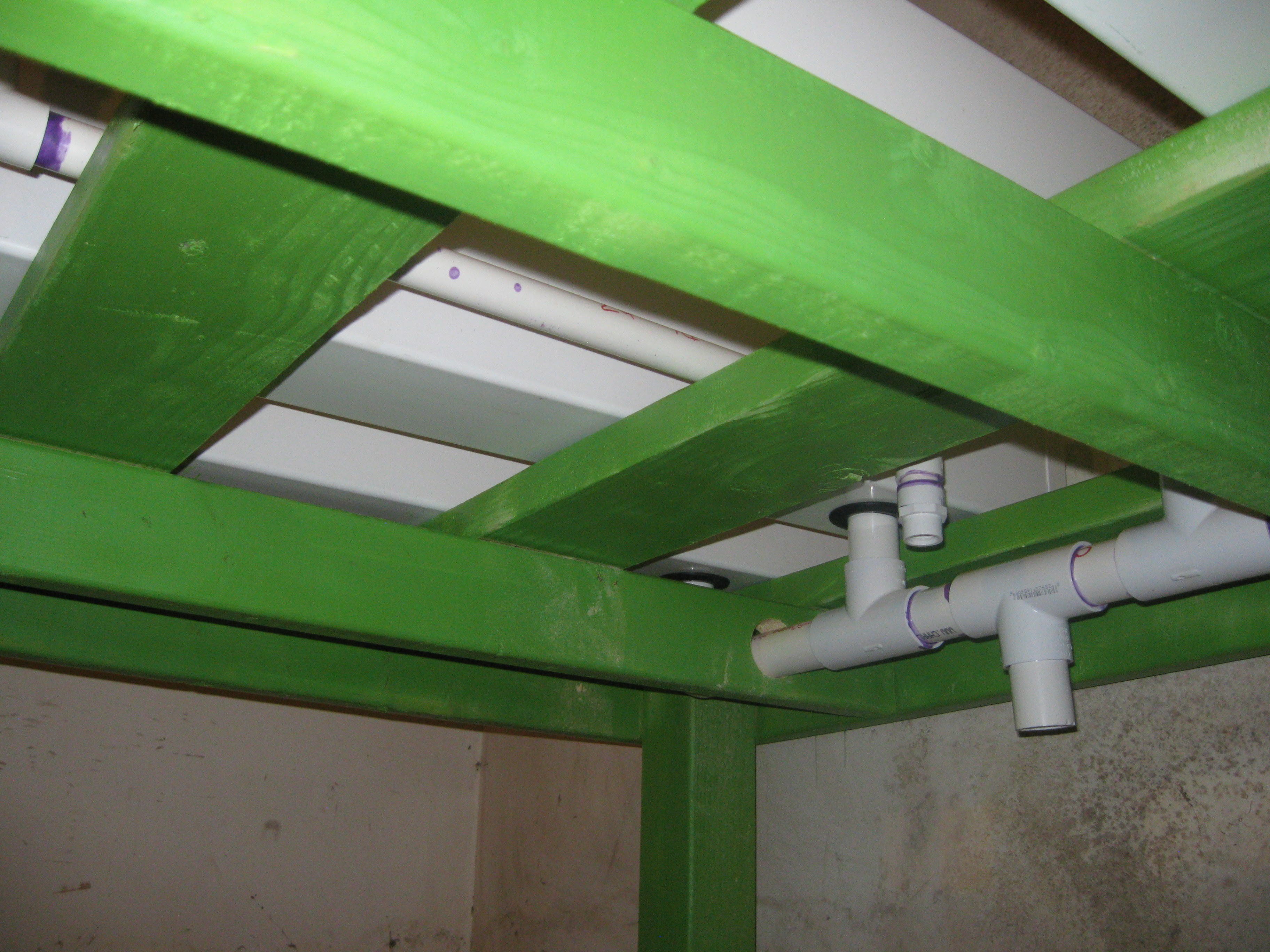
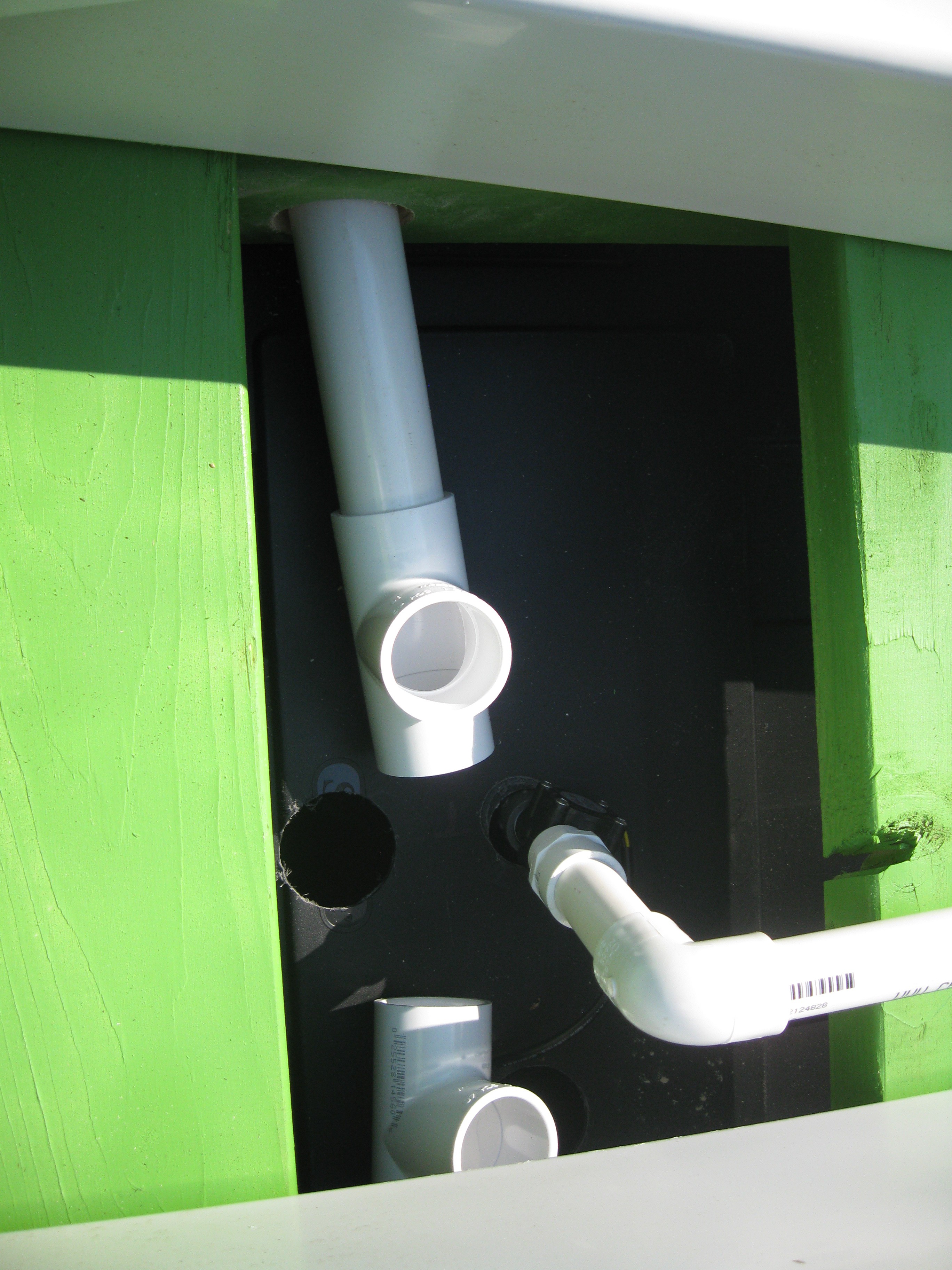
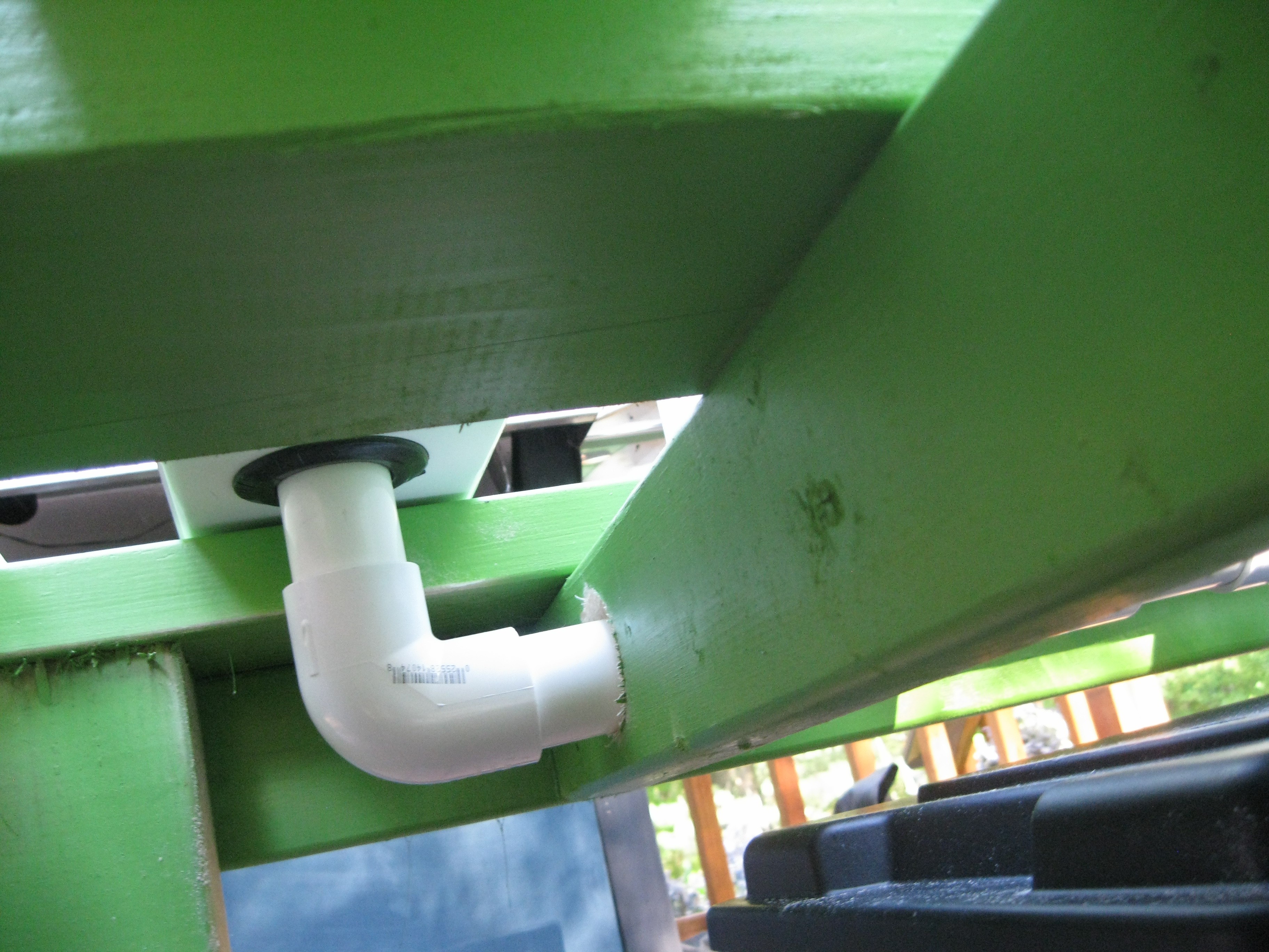
View from beneath, all four drains from the fence post rows converge to this output, it protrudes about an inch into the reservoir.
![]()
Another view from below
![]()
A view from the side below.
![]()
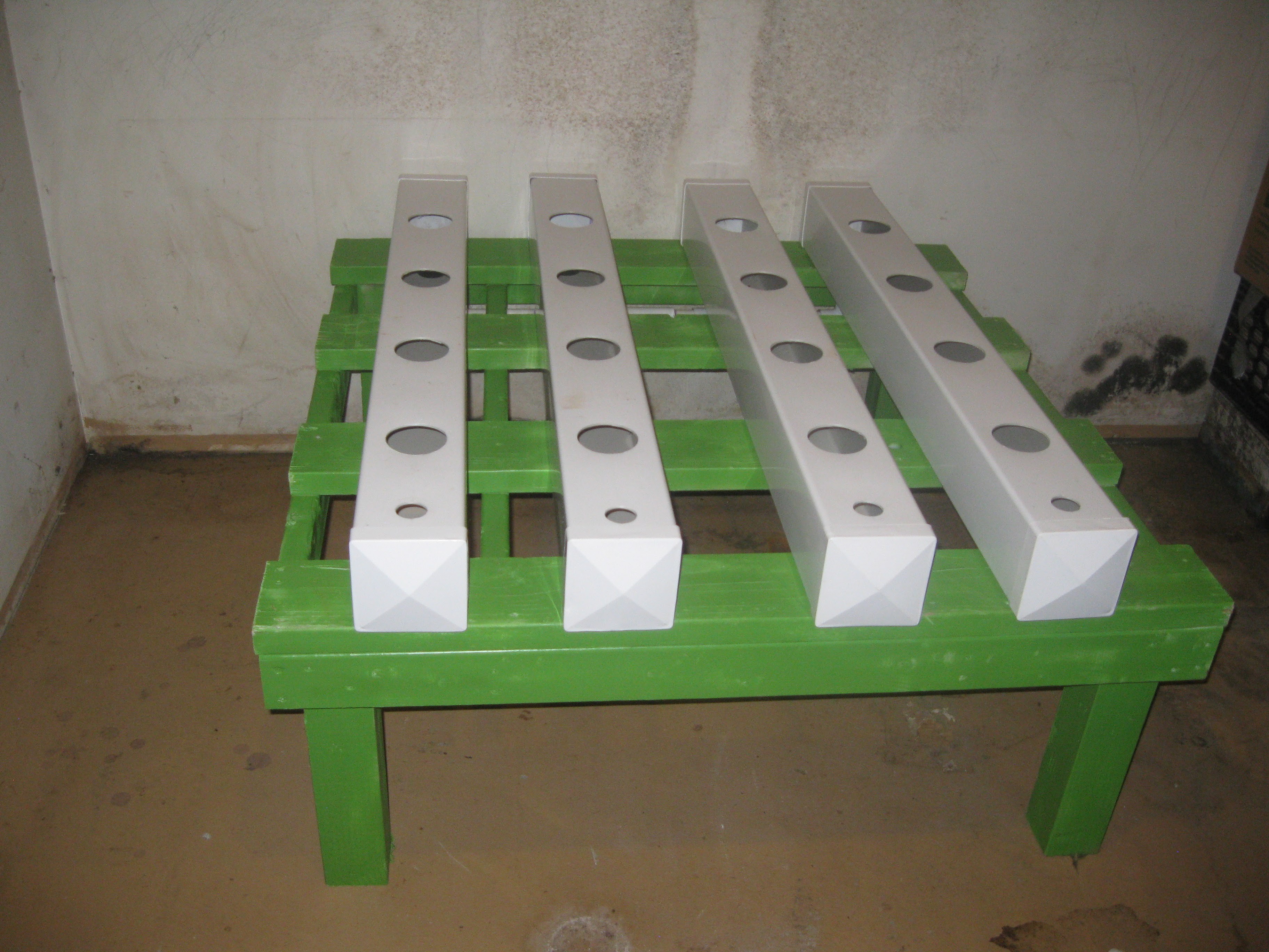
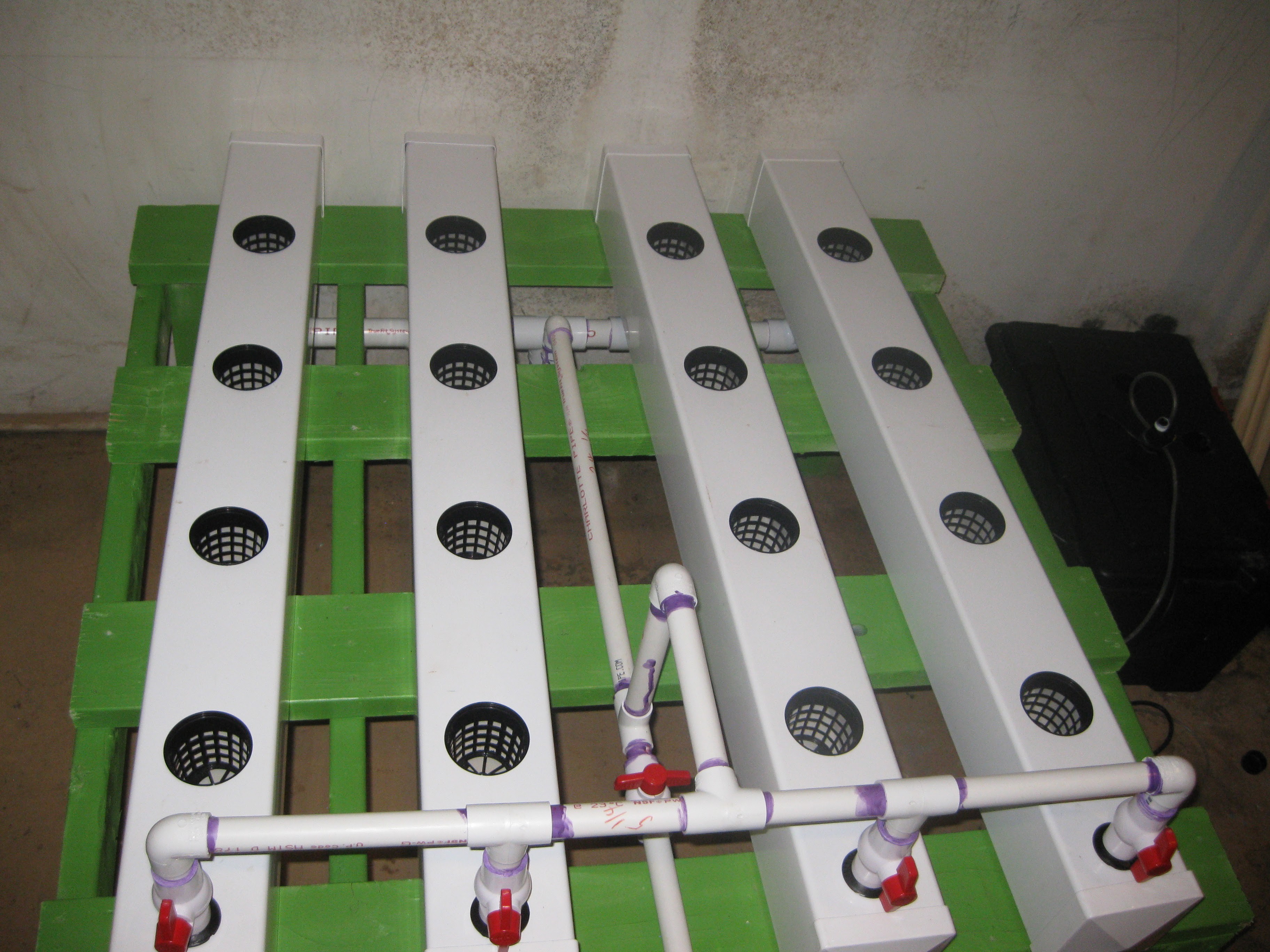
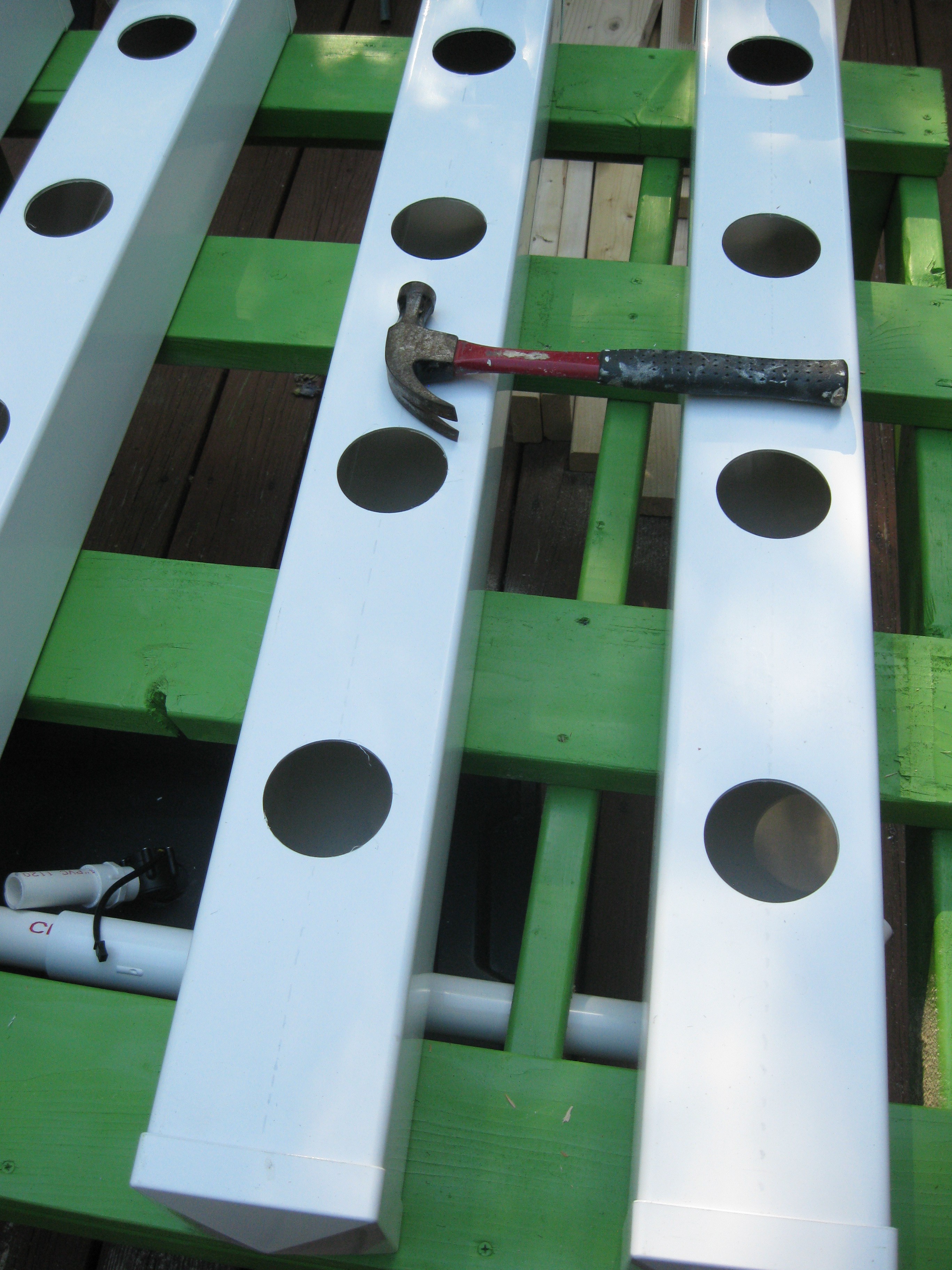
Fence Post Grow Rows installed, they just press fit in place
![]()
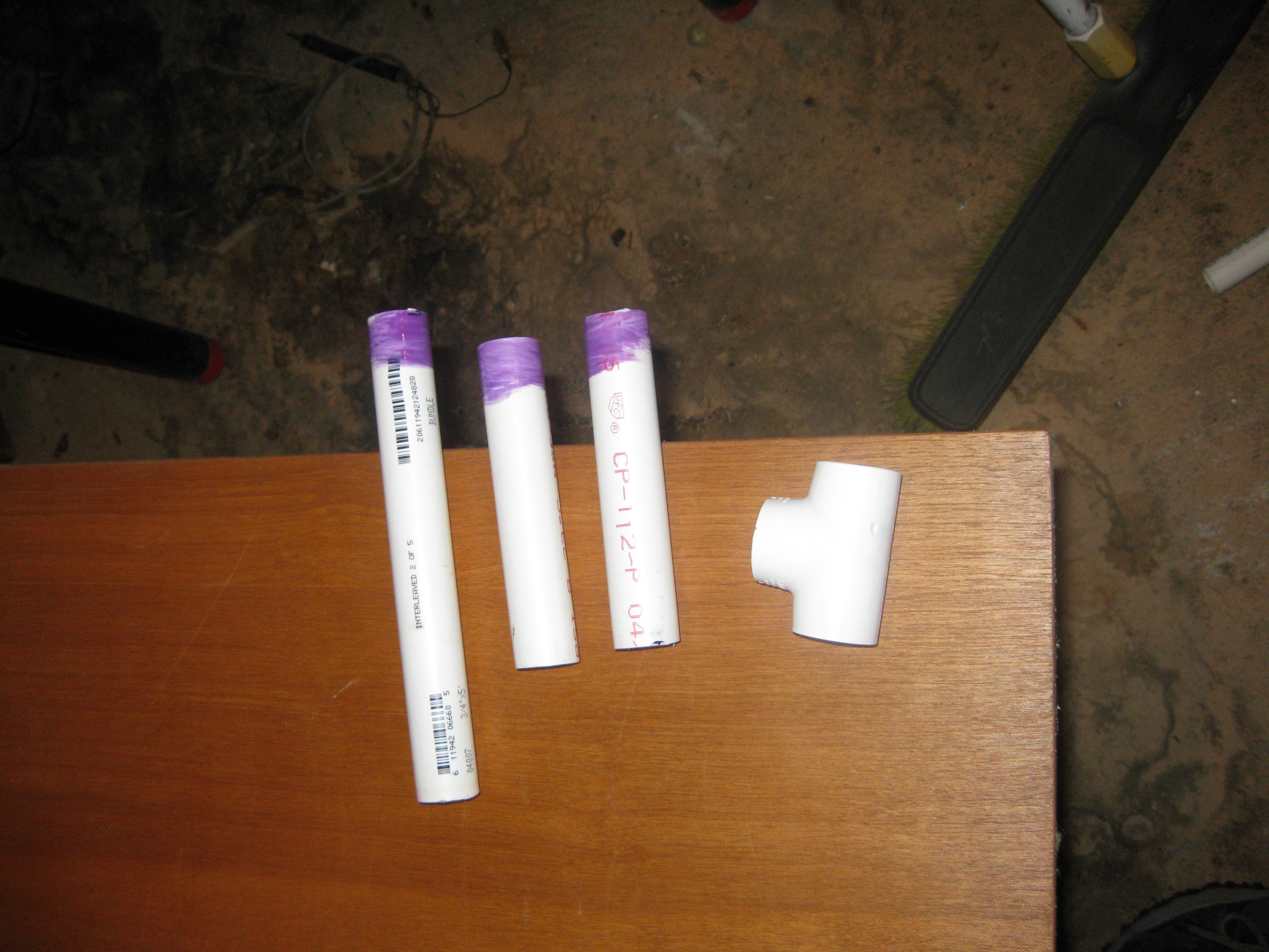
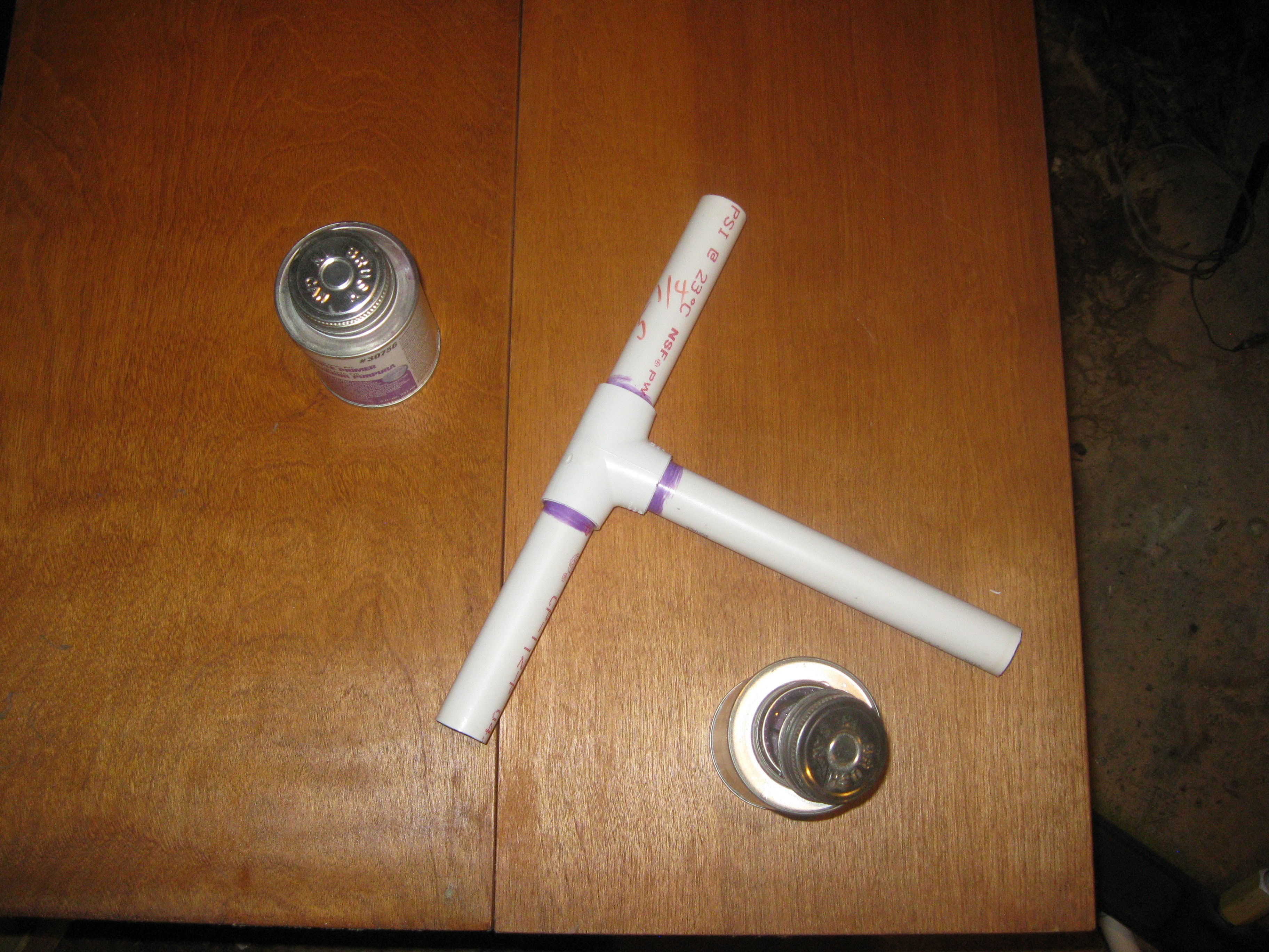
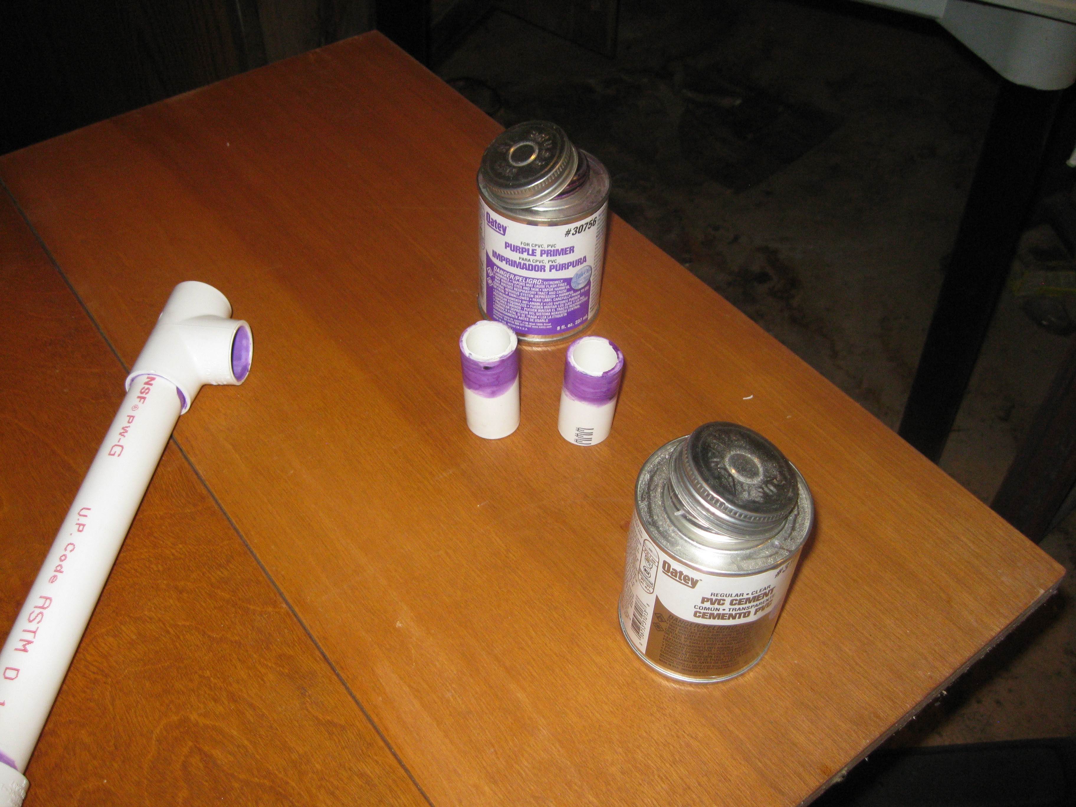
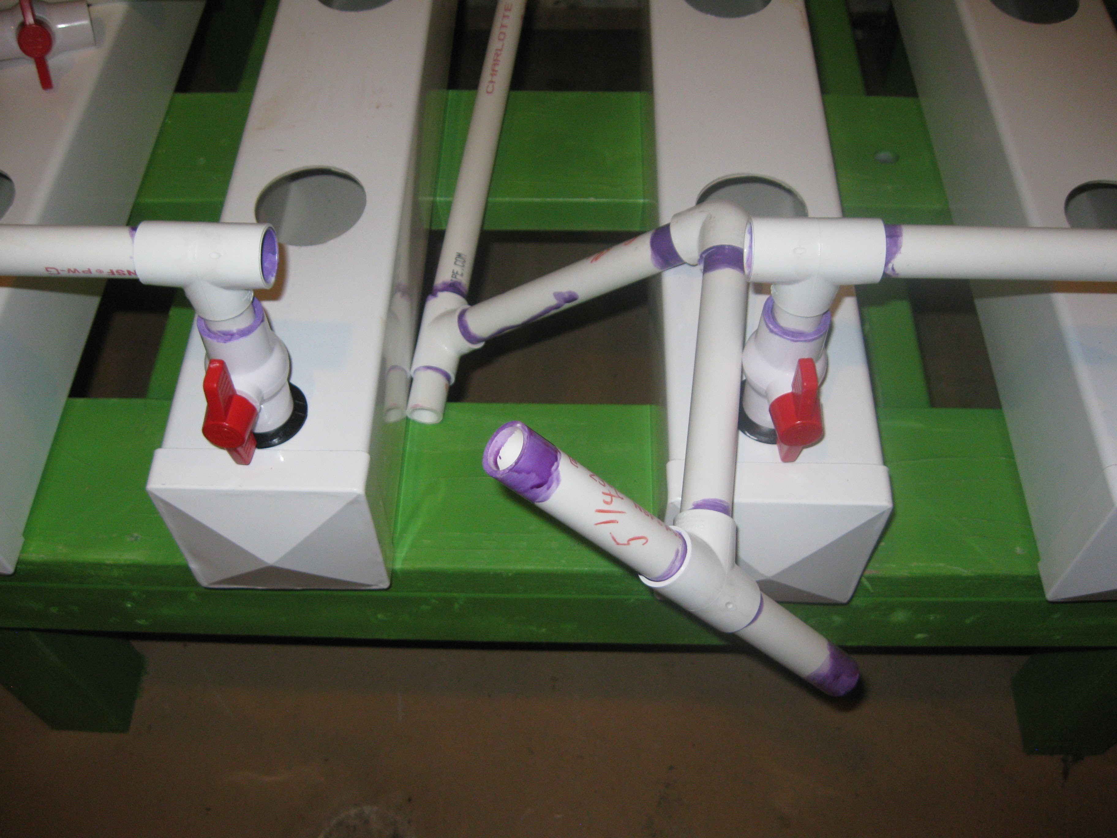
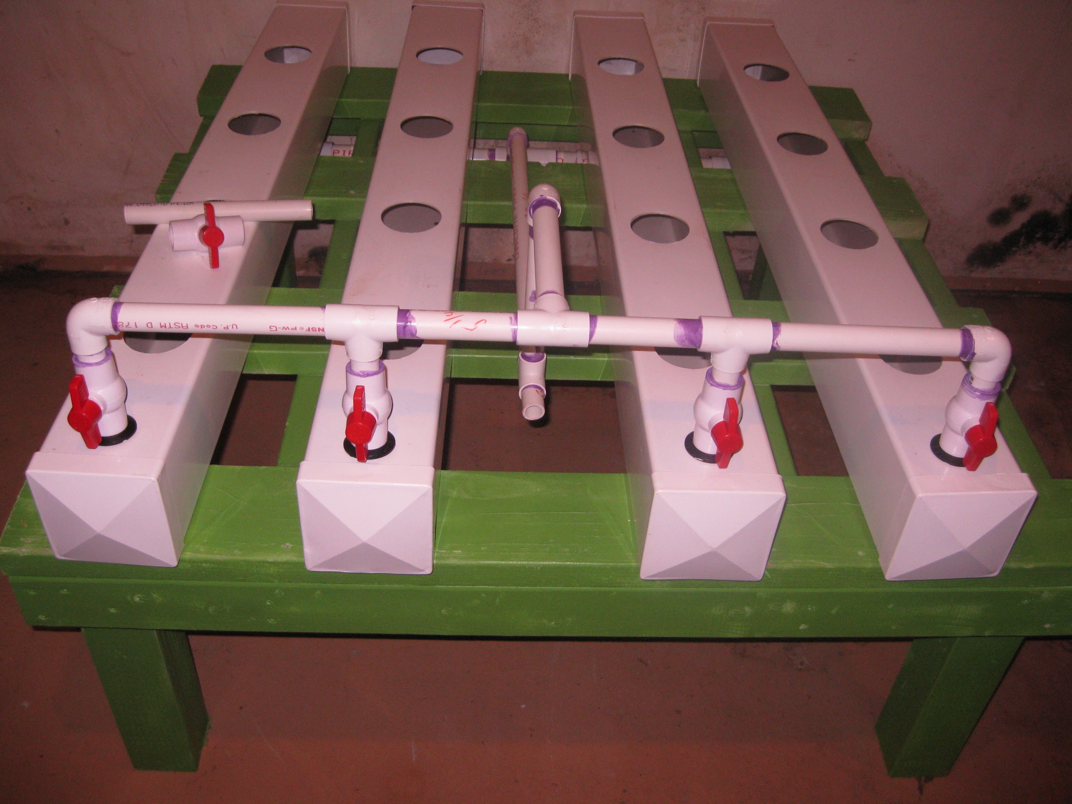
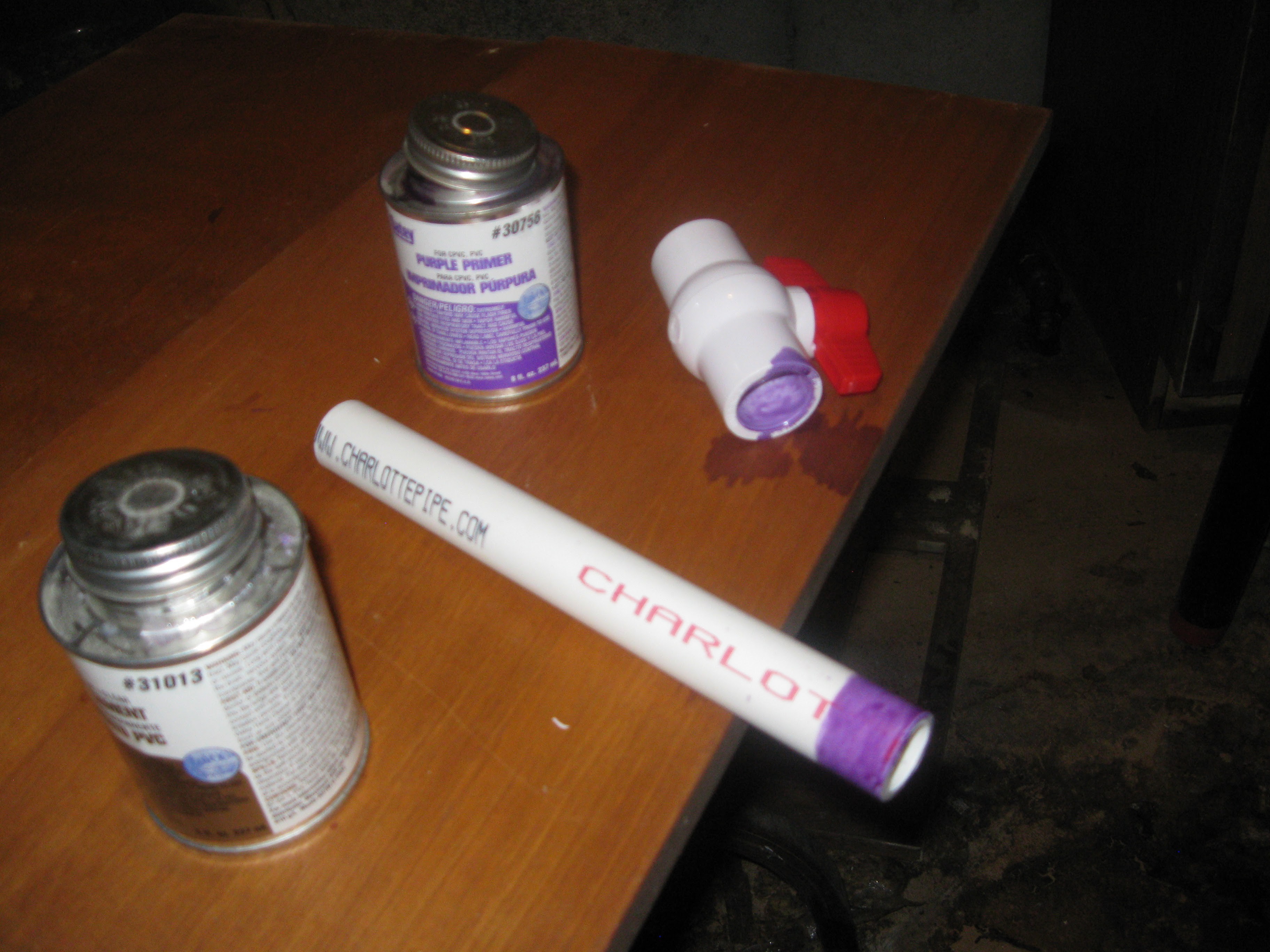
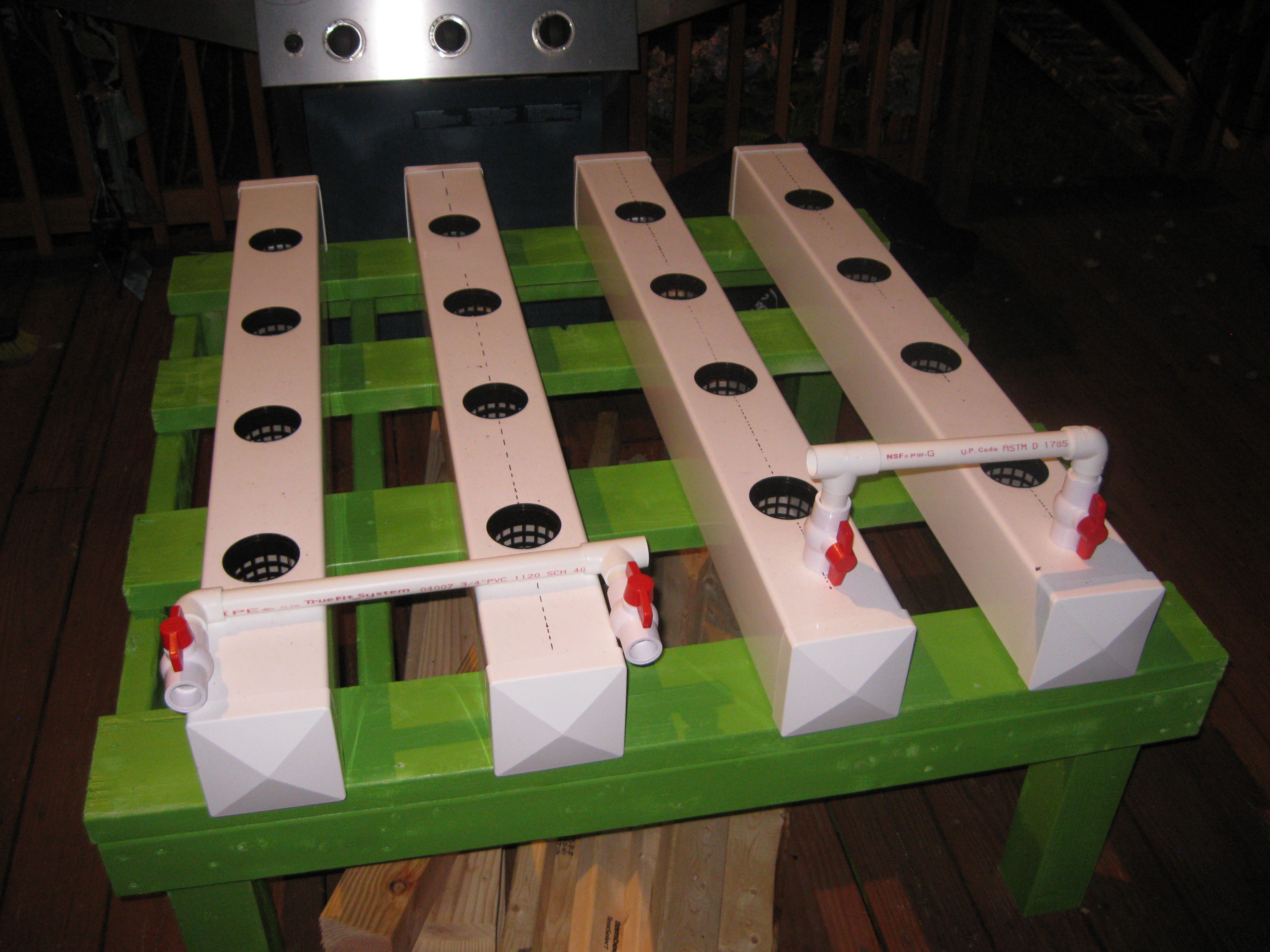
The gluing of the input manifold was a longer more careful process. The input manifold has PVC ball valves for setting the water depth in each row, I decided to assemble the manifold in stages to prevent PVC cement vapor from damaging the valves. As I assembled the manifold I made sure to take down all the lengths of the different pieces of pipe, I will be updating the other project page with this information so anyone out there can build one like mine. Moving on with the photos:
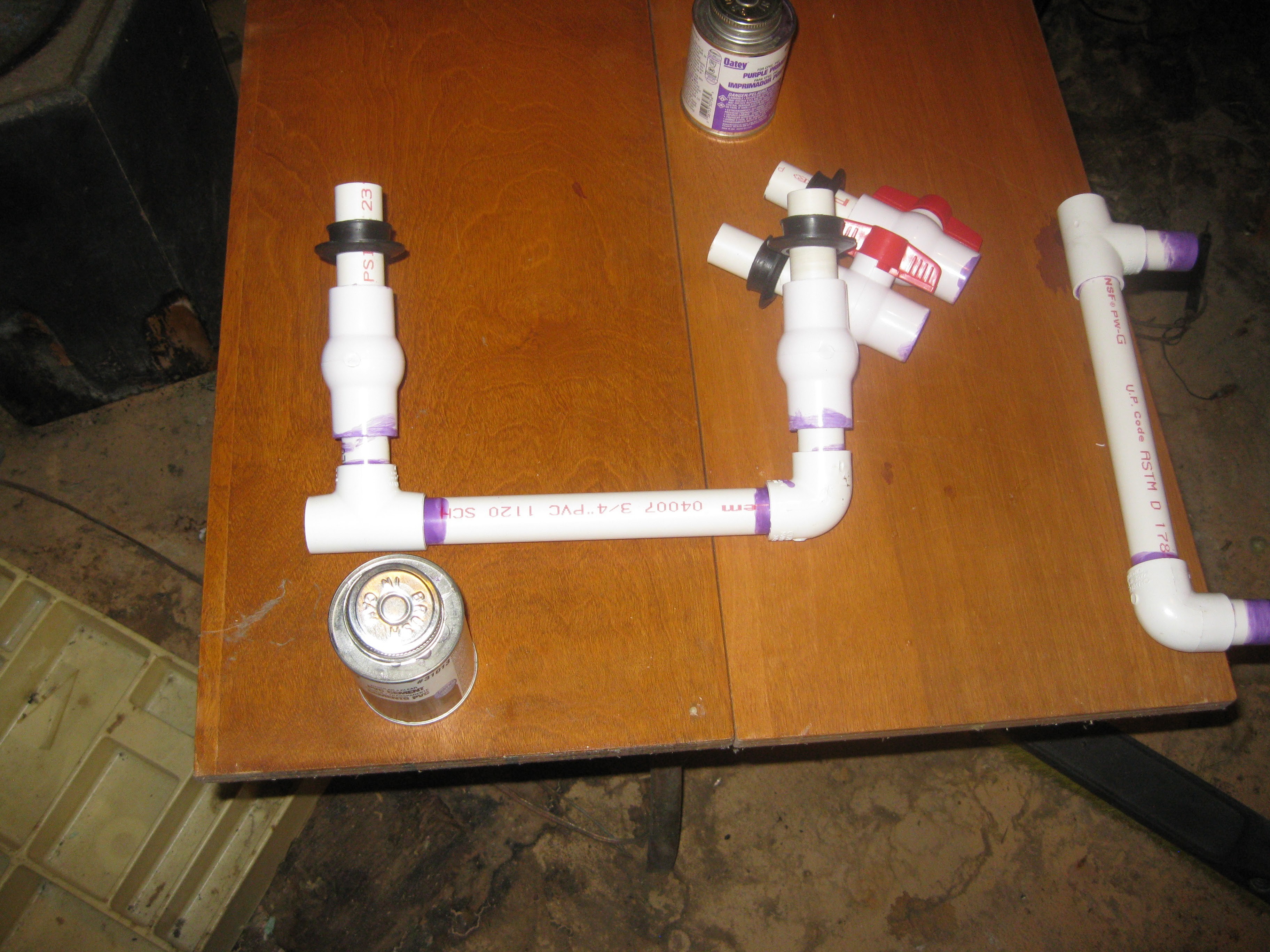
Assembling the t-joining piece
![]()
![]()
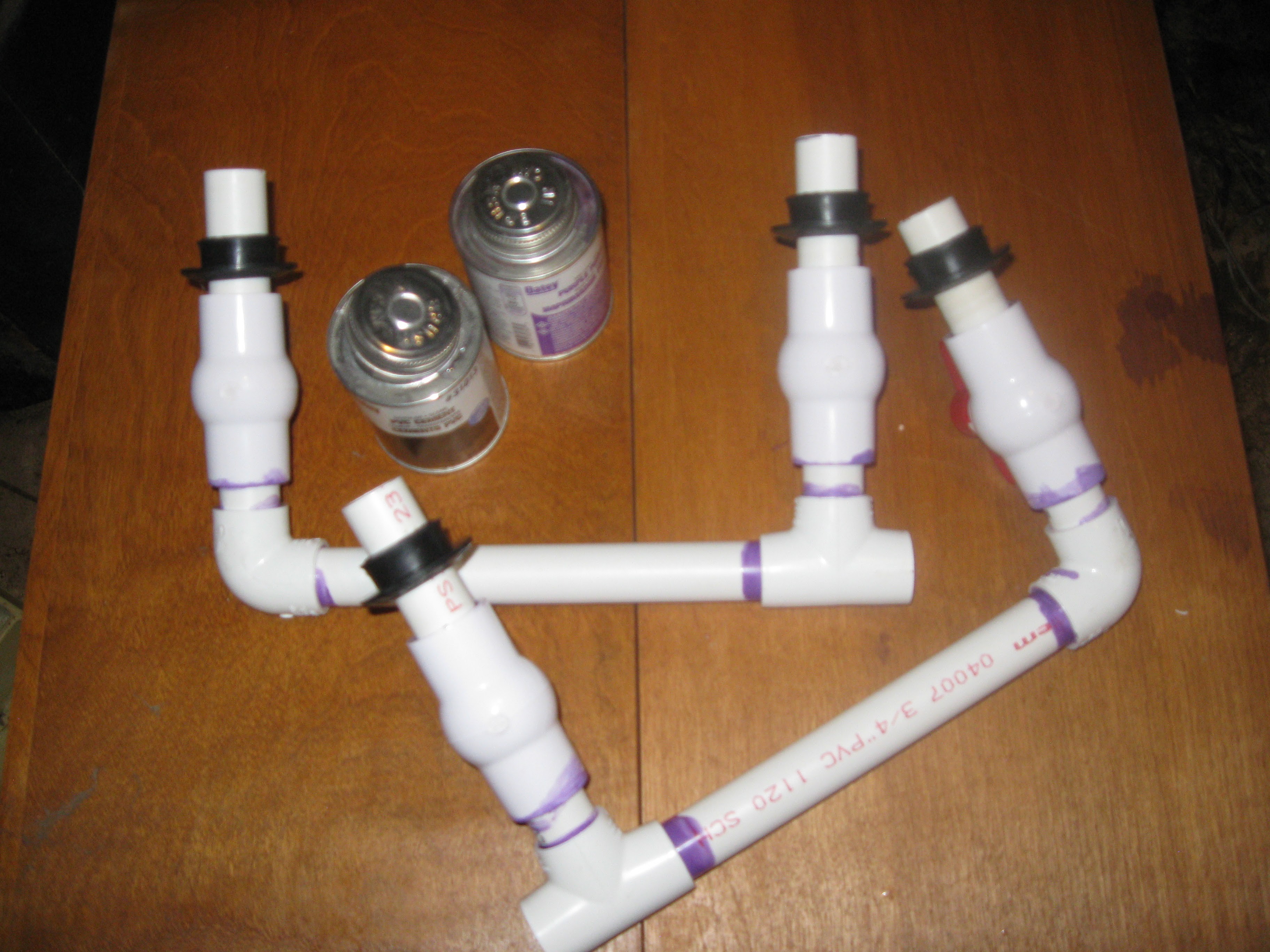
Assembling valve sections of the manifolds. For assembly the manifold was assembled in half essentially, pairing two fence post rows together. Each side of the manifold was assembled separately, with the idea of being installed into place and joined together with the T shaped piece above. This piece is dry assembled here and not yet glued.
![]()
Part of section without valves assembled first. The valves and the pipe for connecting them to the fenceposts were assembled separately.
![]()
This piece connects the pump and flow rate sensor to the manifold.
![]()
Fitting assembly for connecting flow meter to pump and input pipe glued together.
![]()
Gluing one of the manifold halves.
![]()
![]()
![]()
![]()
![]()
Small sections of pipe glued to valves and set to dry, these were attached before gluing the valves into the manifold sections so they would dry a bit before hand to prevent excess vapor of the cement from melting the internals of the valve. Also picture are the two sides of the manifold that the valves glue onto and the fitting assembly for atting the pump and flow meter to the input pipe.
![]()
Beginning the input pipe gluing. the input pipe connects the pump inside the reservoir to the T-shape piece designed to join the two halves of the manifold containing the water level set valves.
![]()
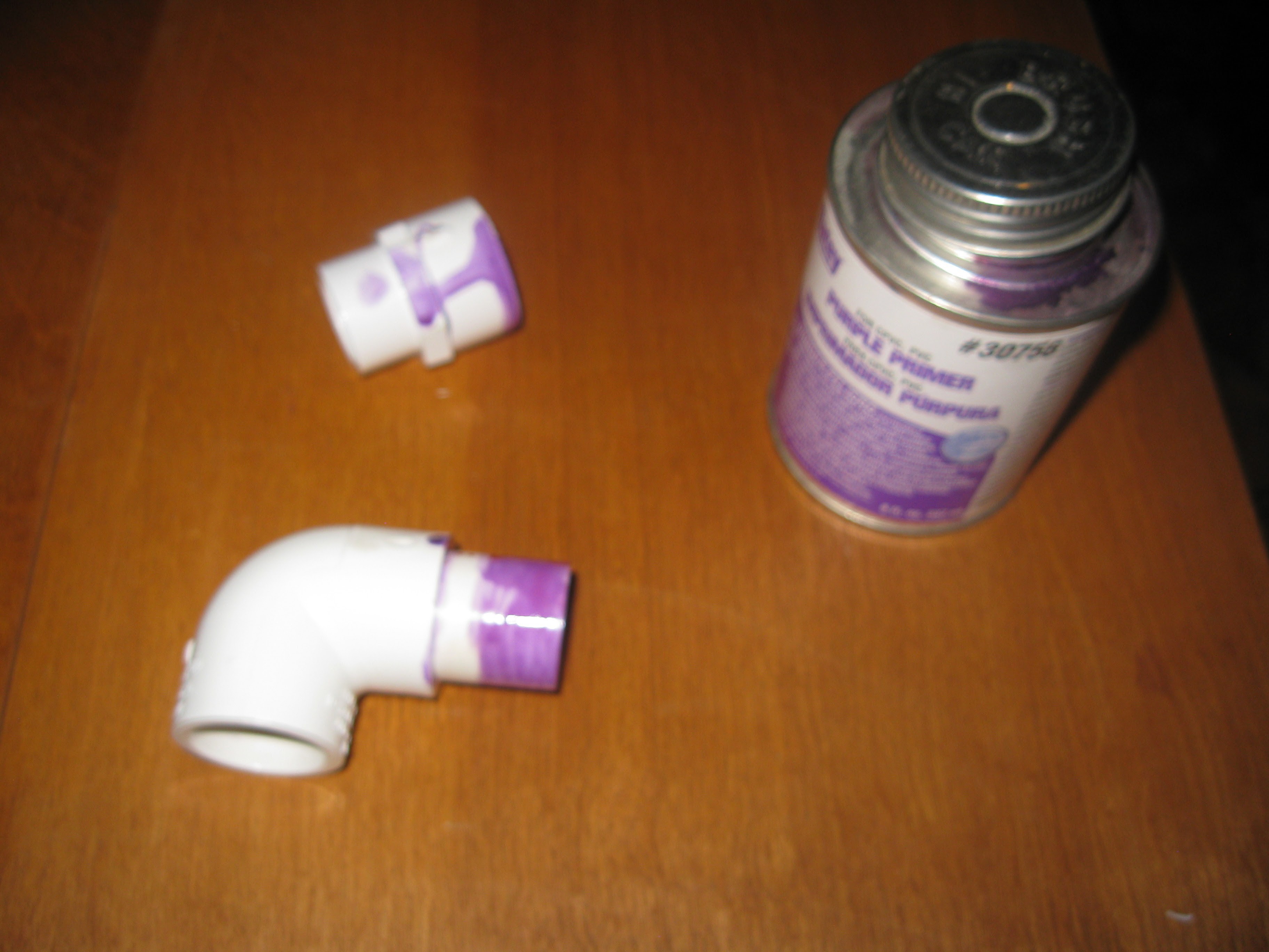
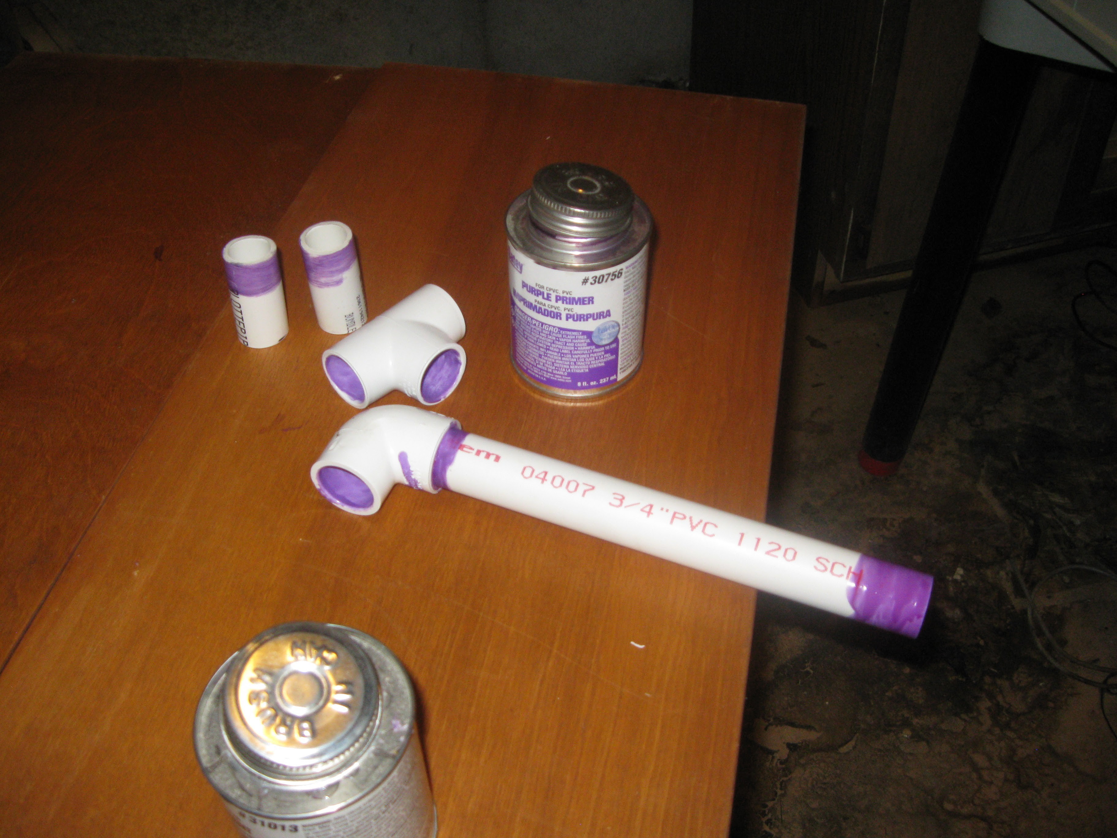
Input pipe assembly components primed for gluing.
![]()
Input pipe assembly in the process of being glued.
![]()
Input pipe and T-shape (joins both sides of manifold) glued and drying for next step.
![]()
T-shape piece and input pipe glued together.
![]()
Manifold pieces glued in sections, set up to dry briefly before valve gluing.
![]()
Pump/flow meter fitting assembly added to input manifold pipe.
![]()
Getting ready to glue the valves onto the two sides of the manifold.
![]()
Adding water level set valves to each side of the input manifold.
![]()
Two sides of the manifold assembled with valves.
![]()
Both completed sections of the manifold placed on either side with the middle T-piece primed and ready for gluing.
![]()
Manifold glued and installed, with the waste water draing valve to be glued in place next.
![]()
Gluing the waste water drain valve and pipe
![]()
Manifold completely Assembled and installed.
![]()
![]()
Both manifolds in place, directly above where the reservoir will be placed, perfect.
![]()
View from below after both manifolds and fence posts rows installed
![]()
Everything in place after moving the rest of the junk out of the space.
![]()
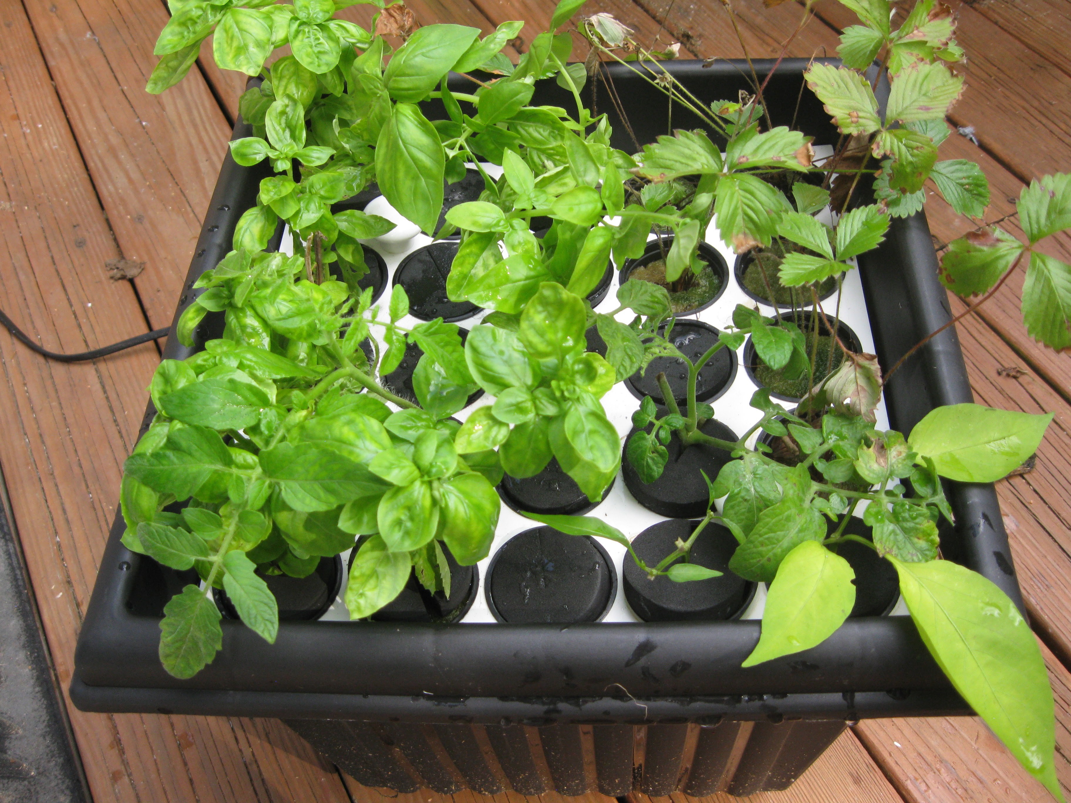
Netted pots in place
![]()
So that wraps up this post, the whole unit is assembled and moved into the basement. Expect updates regarding the lights and transplanting the plants very soon. Next week we are getting back to electronics and software.
-
Java, Plants, And Gluing Endcaps, Oh Boy
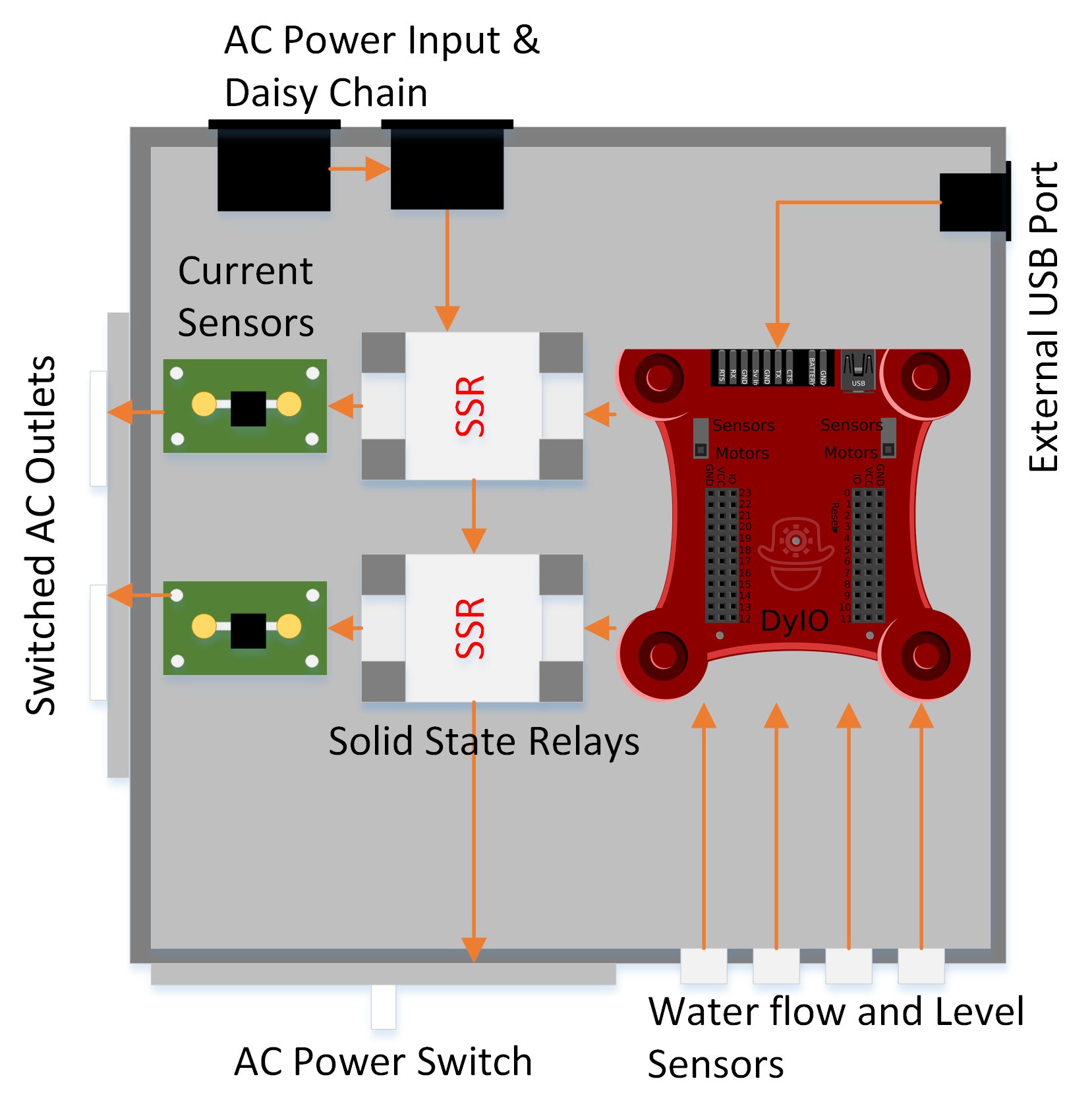
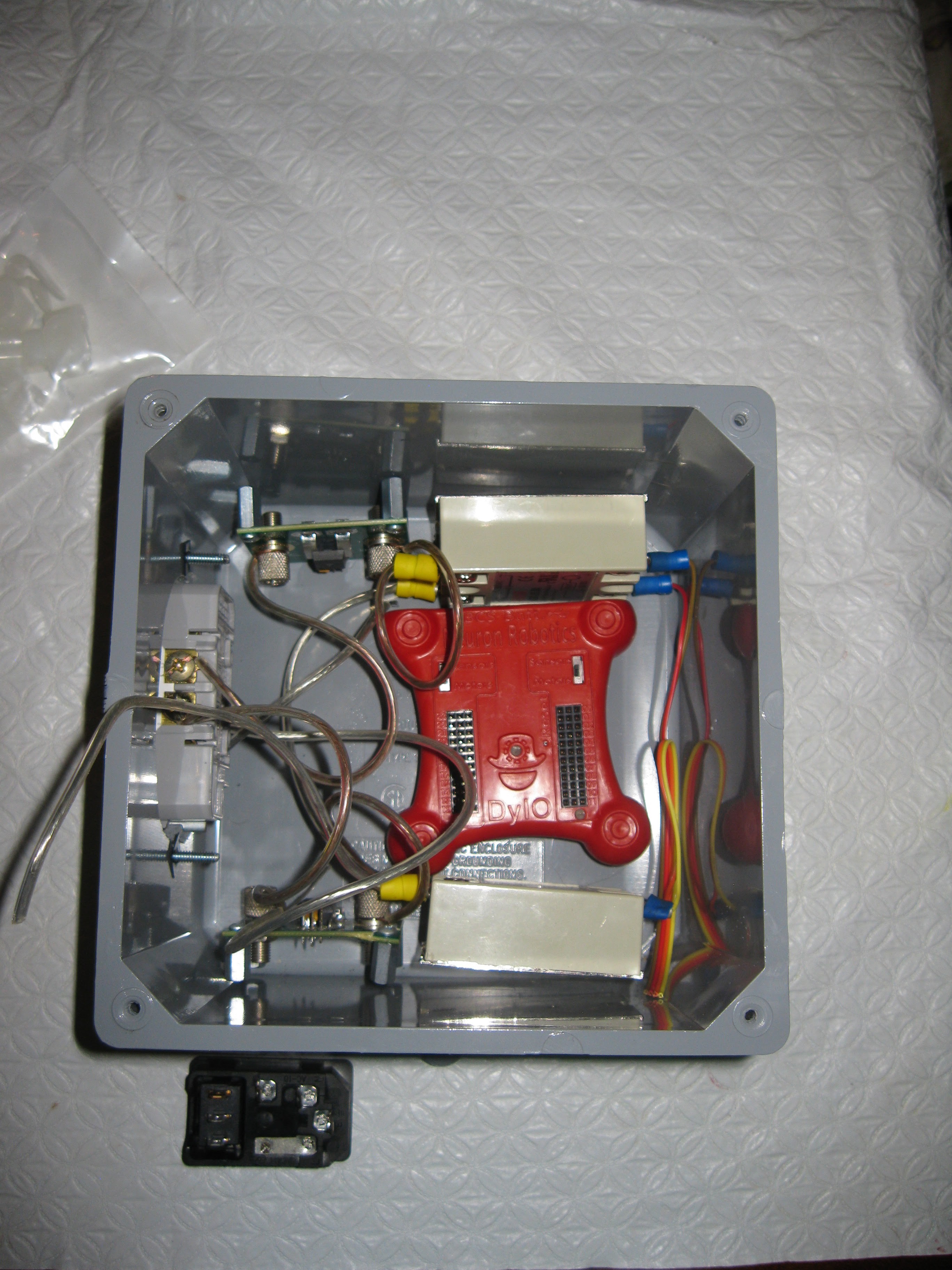
09/01/2015 at 22:27 • 0 commentsSo quite a bit more got done on HydroPWNics since the last update. I did a lot of work on the AC control box discussed in the details section and system design document. Quick refresh: the AC control box is design to control all the AC powered components in the NFT grow system, its based on a DyIO solidstate relays, and two allegro current sensor eval boards. All the circuitry and DyIO will be housed in a PVC electrical box. The box also has connections for water flow and level sensors, since the pump is controlled off AC. The diagram below taken from the details section further explains the internals of the AC control box:
AC Control box
![]()
In the Java application the AC control box is represented by a java class/object, called AC_ControlBox . This class is rather simple, it only contains functions for controlling the relays and reading the current sensors. Right now the class is very simple only setup for manual control of the AC devices from the main application. Later timers, sensor input, and additional intelligent control will be implemented. The idea is to implement the most basic function and debug the hardware along the way, confirming features as functioning one at a time, this is to ease the debugging process as the whole codebase grows.
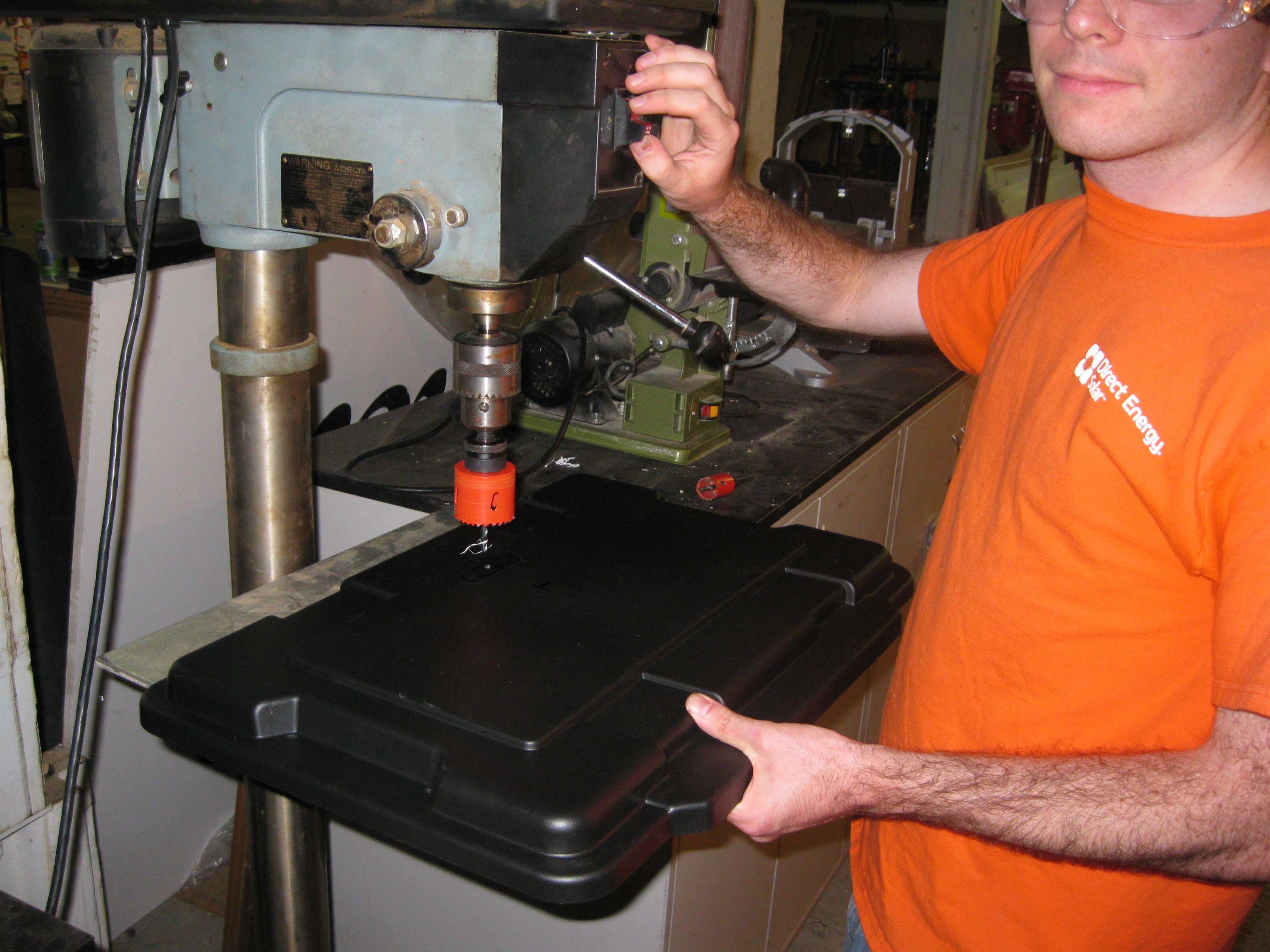
package com.GardenControl.HydroPWNicsApp.github.io;

import com.neuronrobotics.sdk.dyio.DyIO;
import com.neuronrobotics.sdk.dyio.peripherals.AnalogInputChannel;
import com.neuronrobotics.sdk.dyio.peripherals.DigitalInputChannel;
import com.neuronrobotics.sdk.dyio.peripherals.DigitalOutputChannel;

public class AC_ControlBox {
	boolean outlet0_status = false;
	boolean outlet1_status = false;
	int outlet0_current = 0;
	int outlet1_current = 0;

	DyIO AC_CntrlDyIO = null;

	// Digital outputs for triggering SSRs for turning AC outlets on and off.
	DigitalOutputChannel acSSR0 = null;
	DigitalOutputChannel acSSR1 = null;

	// Analog inputs for current sensing on AC outlets
	AnalogInputChannel acSSR0_current = null;
	AnalogInputChannel acSSR1_current = null;

	// Flow Meter Digital Inputs
	DigitalInputChannel flowMeter0_p1 = null;
	DigitalInputChannel flowMEter0_p2 = null;

	// Water Level Sensor Digital Inputs, one per Row
	DigitalInputChannel wtrLvl0 = null;
	DigitalInputChannel wtrLvl1 = null;
	DigitalInputChannel wtrLvl2 = null;
	DigitalInputChannel wtrLvl3 = null;


	/**
	 *
	 * @param dyio
	 */
	public AC_ControlBox(DyIO dyio){
		setupClass(dyio);
		setOutlet0_OFF();
		setOutlet1_OFF();
	}

	/**
	 *
	 * @param dyio
	 * @param outlet0	boolean determining the on/off status of the outlet when AC_ControlBox is instantiated
	 * @param outlet1	boolean determining the on/off status of outlet1 when AC_ControlBox is instantiated
	 */
	public AC_ControlBox(DyIO dyio, boolean outlet0, boolean outlet1){
		setupClass(dyio);
		if(outlet0){
			setOutlet0_ON();
		}
		else{
			setOutlet0_OFF();
		}

		if(outlet1){
			setOutlet1_ON();
		}
		else{
			setOutlet1_OFF();
		}
	}

	/**
	 * Sets up all objects related to class, setup as a function to allow for cleaner constructors
	 * @param dyio
	 */
	private void setupClass(DyIO dyio){
		AC_CntrlDyIO = dyio;
		acSSR0 = new DigitalOutputChannel(AC_CntrlDyIO.getChannel(1));
		acSSR1 = new DigitalOutputChannel(AC_CntrlDyIO.getChannel(2));
		acSSR0_current = new AnalogInputChannel(AC_CntrlDyIO.getChannel(4),true);
		acSSR1_current = new AnalogInputChannel(AC_CntrlDyIO.getChannel(5),true);
		wtrLvl0 = new DigitalInputChannel(AC_CntrlDyIO.getChannel(6));
		wtrLvl1 = new DigitalInputChannel(AC_CntrlDyIO.getChannel(7));
		wtrLvl2 = new DigitalInputChannel(AC_CntrlDyIO.getChannel(8));
		wtrLvl3 = new DigitalInputChannel(AC_CntrlDyIO.getChannel(9));
		flowMeter0_p1 = new DigitalInputChannel(AC_CntrlDyIO.getChannel(10));
		flowMEter0_p2 = new DigitalInputChannel(AC_CntrlDyIO.getChannel(11));

	}

	// Outlet 0 Control Functions
	/**
	 *
	 */
	public void setOutlet0_ON(){
		acSSR0.setHigh(true);
		outlet0_status = true;
	}
	/**
	 *
	 */
	public void setOutlet0_OFF(){
		acSSR0.setHigh(false);
		outlet0_status = false;
	}
	/**
	 *
	 * @return
	 */
	public boolean getOutlet0_STATUS(){
		return outlet0_status;
	}
	/**
	 *
	 * @return
	 */
	public int getOutlet0_CURRENT(){
		return outlet0_current;
	}


	// Outlet 1 Control Functions
	/**
	 *
	 */
	public void setOutlet1_ON(){
		acSSR1.setHigh(true);
		outlet1_status = true;
	}
	/**
	 *
	 */
	public void setOutlet1_OFF(){
		acSSR1.setHigh(false);
		outlet1_status = false;
	}
	/**
	 *
	 */
	public boolean getOutlet1_STATUS(){
		return outlet1_status;
	}
	/**
	 *
	 * @return
	 */
	public int getOutlet1_CURRENT(){
		return outlet1_current;
	}


	public void setupOutletAsTimedPump(int outlet_num){

	}

	public void setupOutletAsFlowTestPump(int outlet_num){

	}

	public void setupOutletAsWaterLevelPump(int outlet_num){

	}

}
Also since last update I made quite a bit of progress building the AC control box itself. For the box I am using a Cantex electrical box, they can be bought online from a variety of retailers, I forget where I got mine exactly. I started by using a hole saw to drill two holes close together to mount the two socket AC outlet. The outlet is screwed in place with a bezel mounted over it to make it all look nice. Most of the other work on the box was with wiring, making cables and hooking everything together. I also spent some time placing the guts around in the box, I'm not 100% sure how I'm gonna mount it but what I have in the picture is what I'm considering.
AC Control Box being built:![]()
Soldering connectors to wires for relays
![]()
AC control box being laid out, the outlet is installed but I need to measure and drill holes for the rest of the mounting. Also still need to decide whether the electronics will be laid out this way or if I lay them out a different way.
![]()
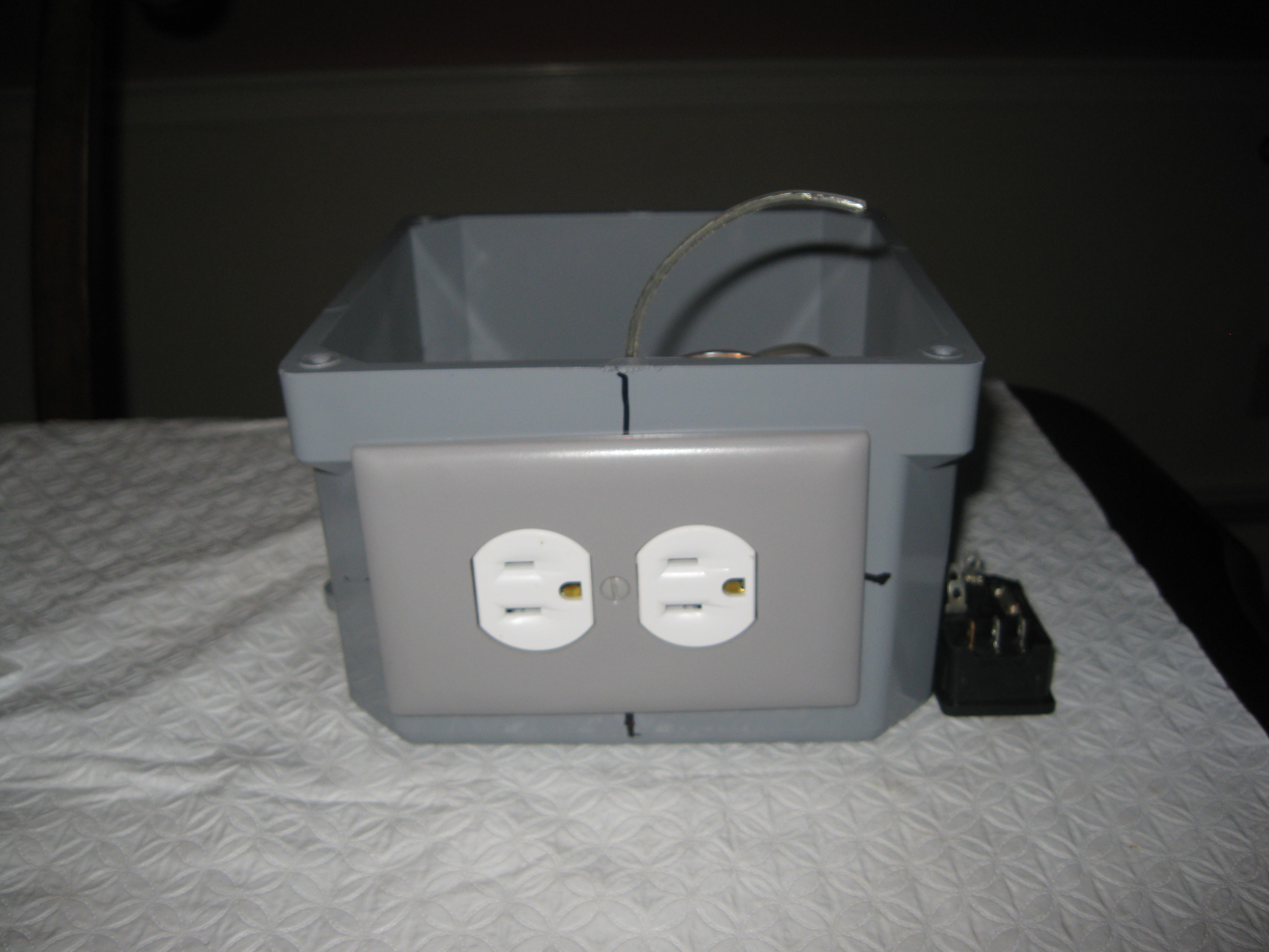
Side view of AC Box showing the two outlets
![]()
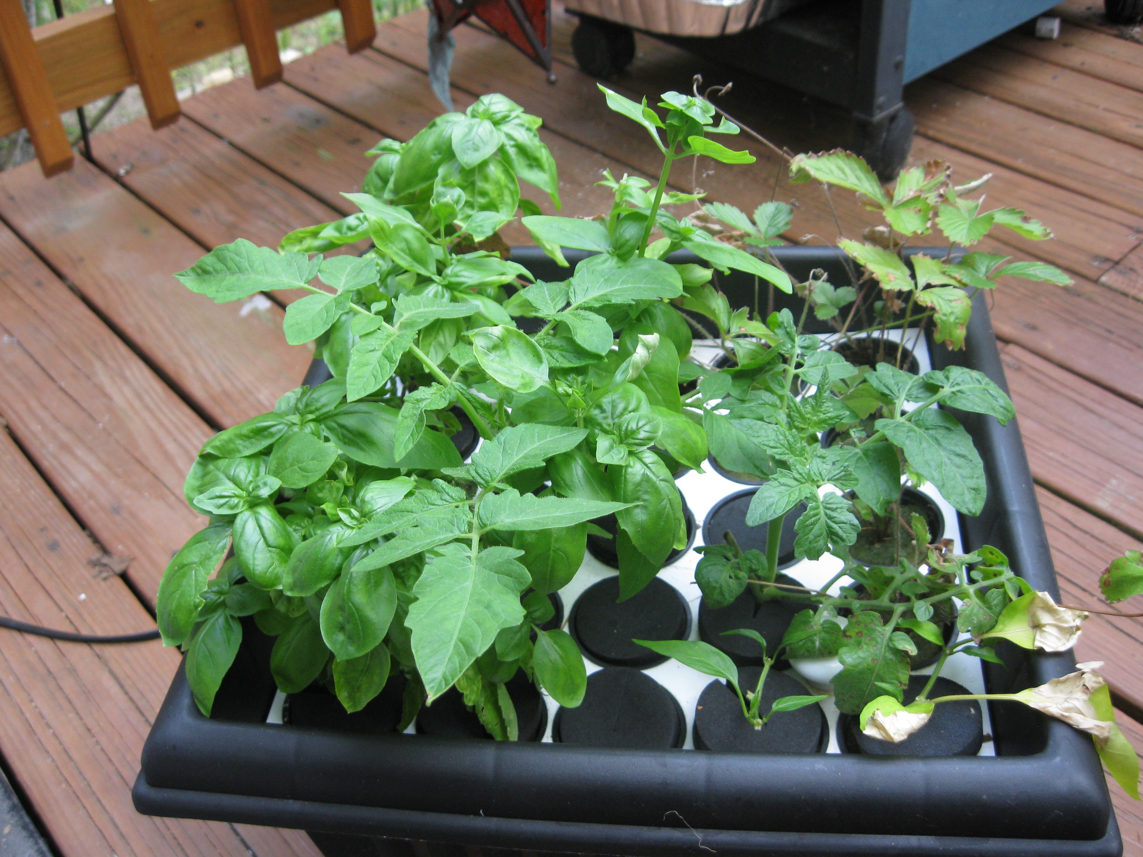
The plants have been doing quite well since the last update on them. The strawberries still haven't done much since I put them in the cloner a month ago so I won't be discussing them much. Moving onto the other plants, all of them have excellent root growth, great leaf color, and accelerated vegative growth. The peppers that just sprouted roots the last time have grow a bit more, I was worried that they weren't doing too well because they shed a lot of leaves but the root growth is up and new leaves are forming! The tomatoes and basil are doing the best, they have a lot of leave growth and significant root growth. The cheap Maxi Gro nutrients are working pretty well, I have high hopes of putting really healthy plants into the NFT when I get it up and running. That was sort of the goal to produce quality plants beforehand so that I can start generating lots of data about how the unit runs and generate lots of plant data for the cloud.
A nice picture of the cloner
![]()
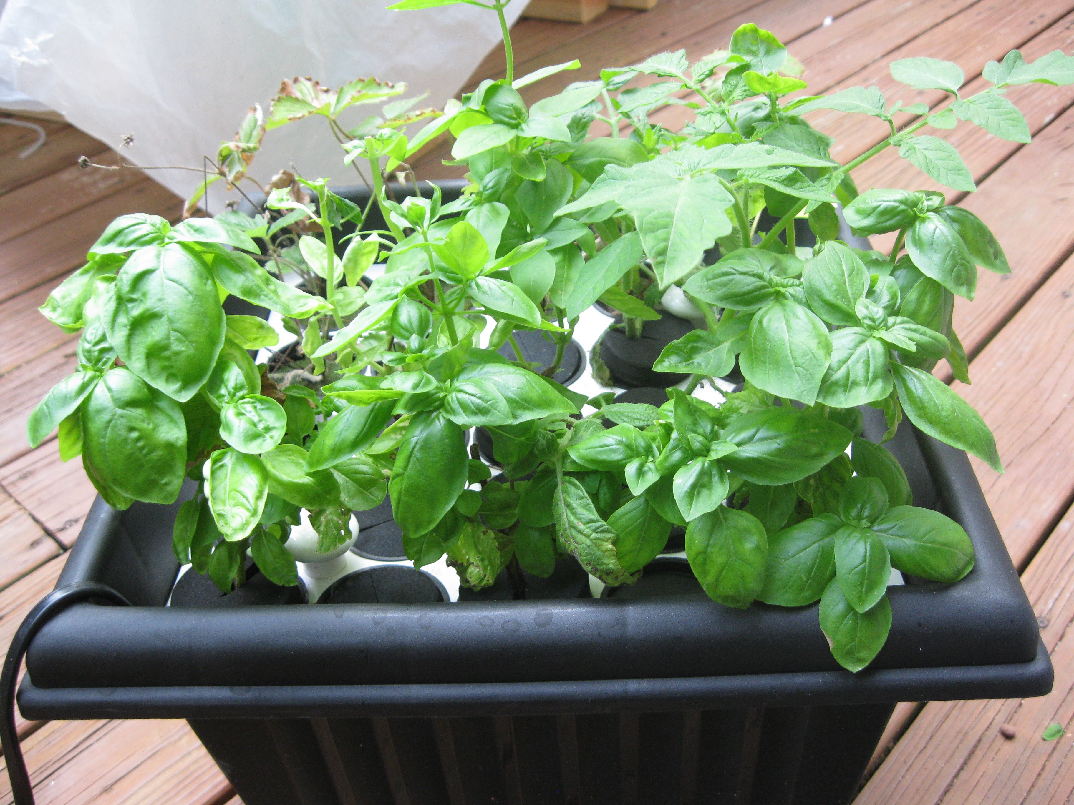
Another shot from another side
![]()
Jalapeno pepper plant finally has some roots
![]()
The other pepper plant
![]()
Over this past weekend I bought the gel PVC cement for PVC fence post gluing and glued the endcaps. To glue the endcaps to each section of post, I lined the lip of the cap and the crease where the cap meets the end of the cut post well with glue. After glue was applied to an endcap it was placed onto an end of post. I did each post one at a time gluing both endcaps on. I used a bungee cord to hold each endcap down tightly, I let each one sit for about 2 hours before switching to different post.
![]()
![]()
![]()
![]()
![]()
Days after the gluing though I noticed that there was some warping and melting to the endcaps, I am not sure if this is going to cause me any problems yet. I looked inside each post with a flashlight, the seem/crease where the end cap meets the post seems to be complete solid and filled in with dryed cement/PVC goo. Anyways just in case I plan on sealing the caps from the outside with silicon. On the next version I build of this system I think I'm going to attach the endcaps with silicon, this way the seal will be tight, and I can take the assembly apart for easier cleaning. Stay tuned for more updates !!!!!
-
Semi-Finals: Its Go Time and Much More
08/29/2015 at 07:19 • 2 commentsFirst off I'd like to say how excited I am to be in the top 100 projects, feels great to be listed among so many great projects! I'd like to thank Hackaday and the judges for being chosen for the final running, thank you so much!
Moving on to updates within the project. Several developments have occurred over the last two weeks. Before I mentioned that the project will be collaborating with vivaplanet.io for a database to store plant data. The news is that vivaplanet.io will also serve as the webui for hydroPWNics rather than a dedicated website. This simplifies things greatly for development and potential users if the project ever sees widespread adoption. Additionally one of vivaplanet.io's developers and HydroPWNics collaborator Shane Kirkbride developed a Java API for communicating with Vivaplanet.io (e.g. pushing data via JSON). The code is view-able in this post and available on the HydroPWNics github page, its a work in progress but an excellent and necessary step forward.
DeviceReport.java
/*
 * To change this template, choose Tools | Templates
 * and open the template in the editor.
 */
package vivaplanetjava0;

/**
 *
 * @author Shane
 */
public class DeviceReport
{
    private String DeviceID;

    public String getDeviceID() { return this.DeviceID; }
    public void setDeviceID(String DeviceID) { this.DeviceID = DeviceID; }

    private String Address;

    public String getAddress() { return this.Address; }
    public void setAddress(String Address) { this.Address = Address;; }

    private Sensors[]  DeviceSensors;

    public Sensors[] getDeviceSensors() { return this.DeviceSensors; }
    public void setDeviceSensors(Sensors[] DeviceSensors) { this.DeviceSensors = DeviceSensors; }

}
Sensors.java
/*
 * To change this template, choose Tools | Templates
 * and open the template in the editor.
 */
package vivaplanetjava0;

/**
 *
 * @author Shane
 */
public class Sensors
{
    public String SensorType;

    public String getSensorType() { return this.SensorType; }
    public void setSensorType(String SensorType) { this.SensorType = SensorType; }

    public String Reading;

    public String getReading() { return this.Reading; }
    public void setReading(String Reading) { this.Reading = Reading; }

    public String Value;

    public String getValue() { return this.Value; }
    public void setValue(String Value) { this.Value = Value; }

}
VivaPlanetJava0.java
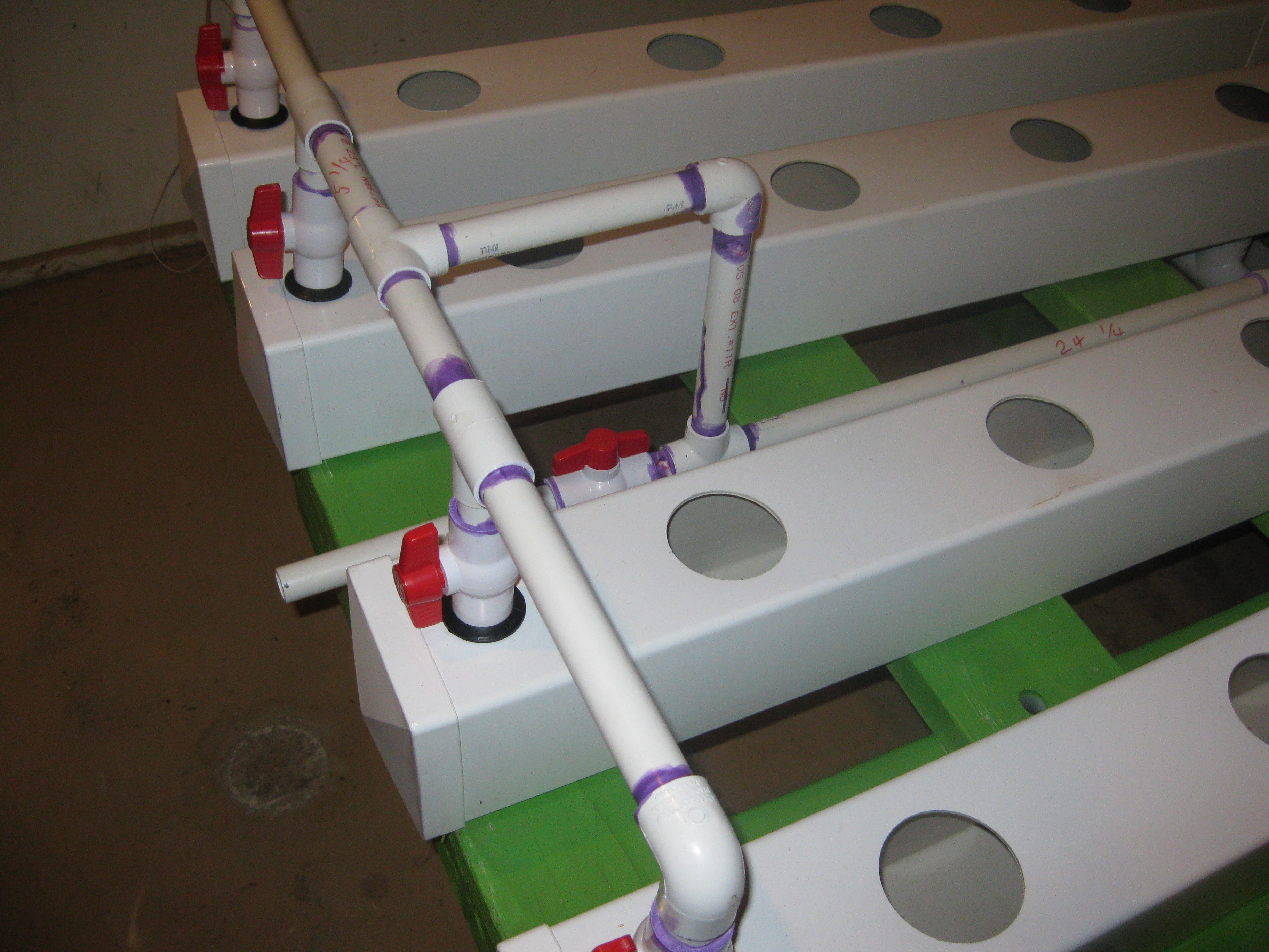
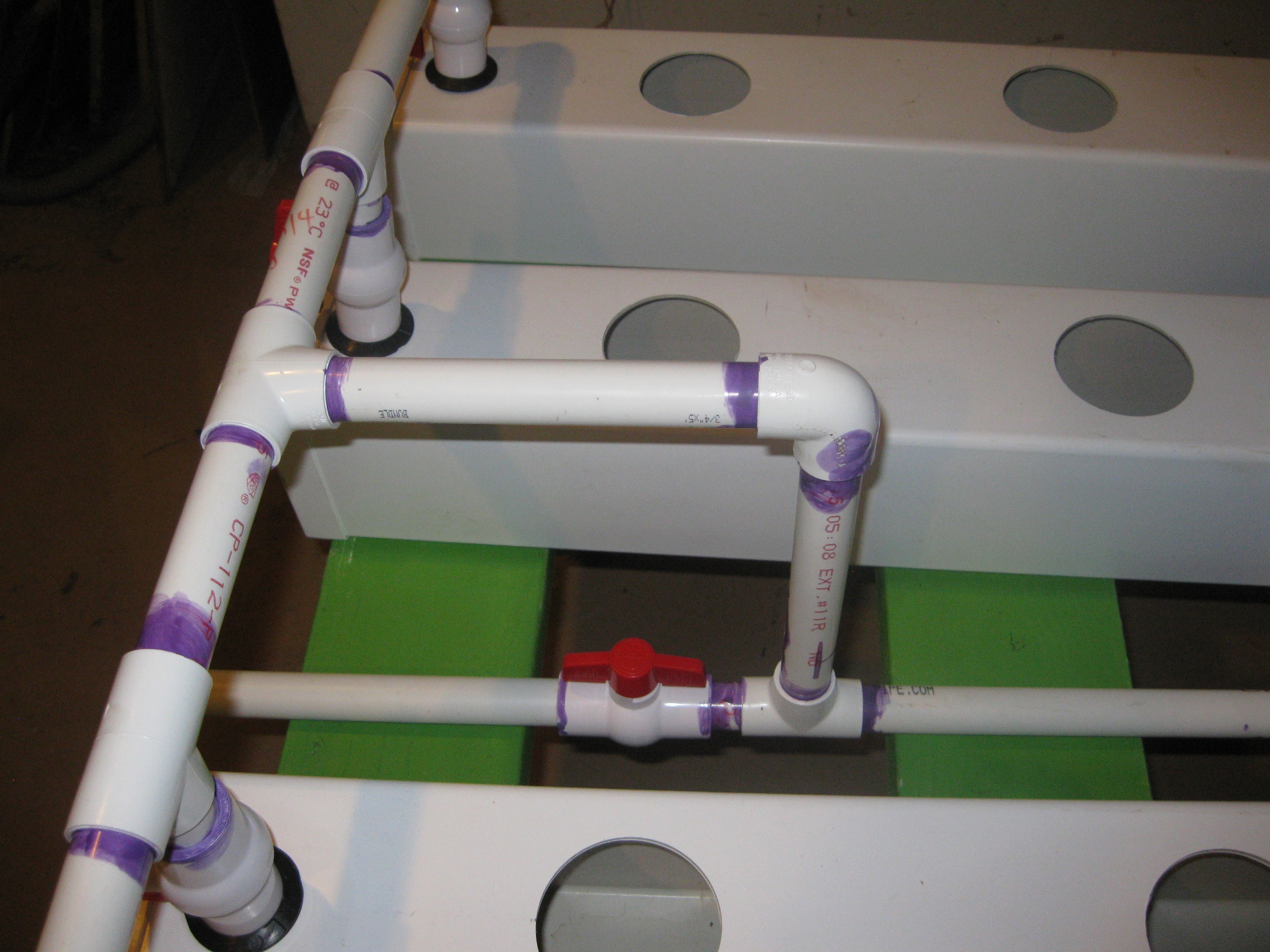
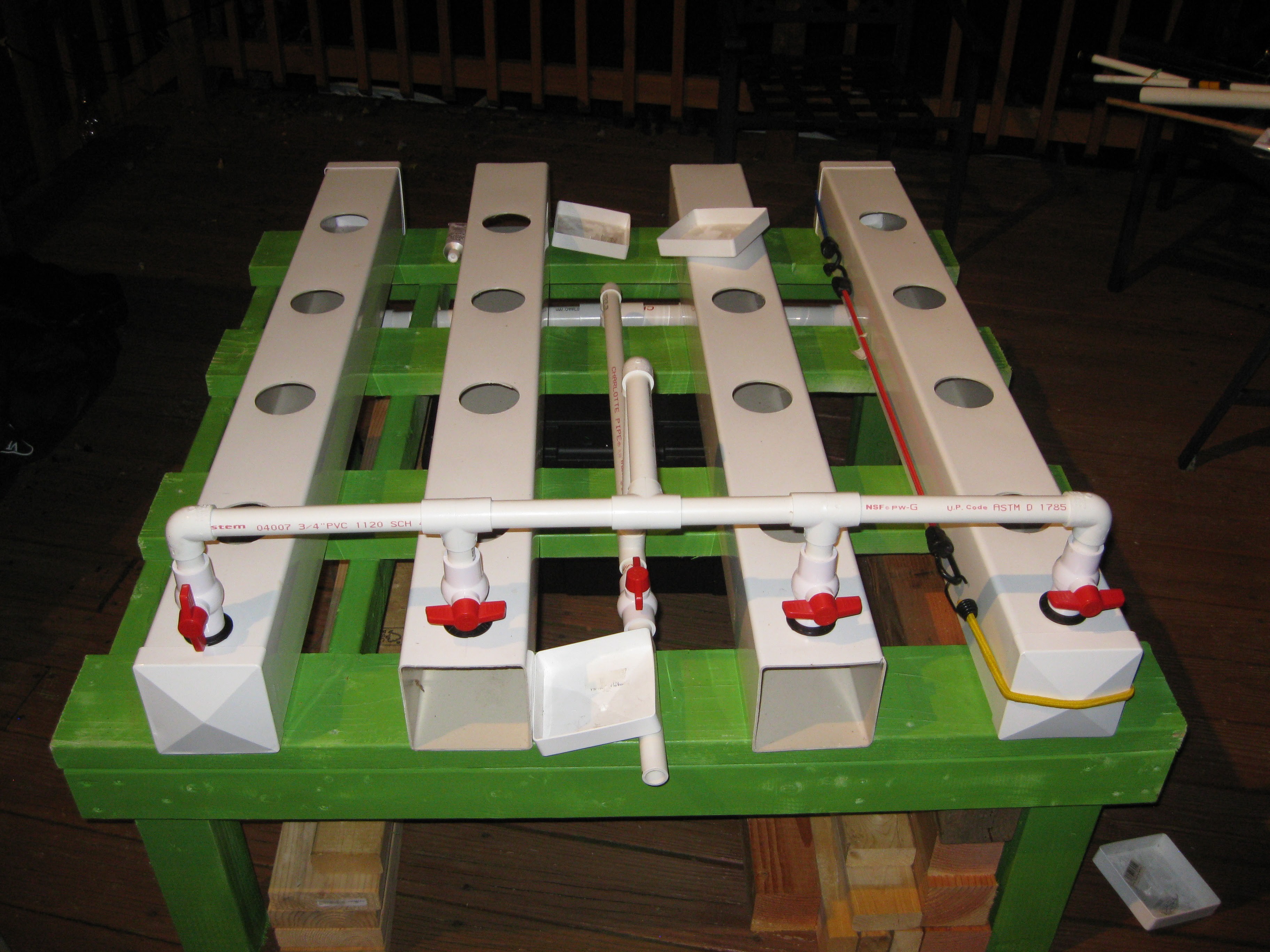
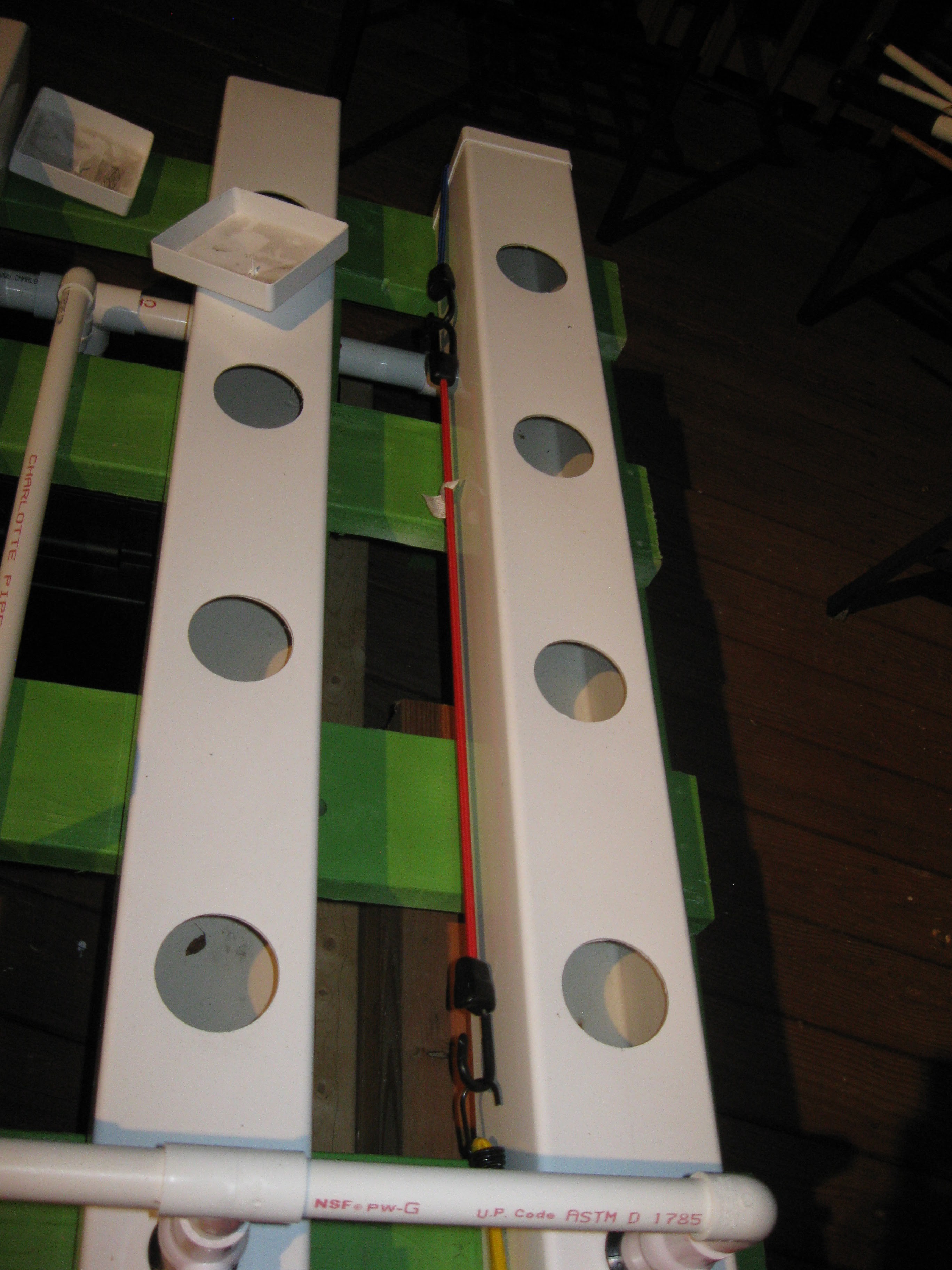
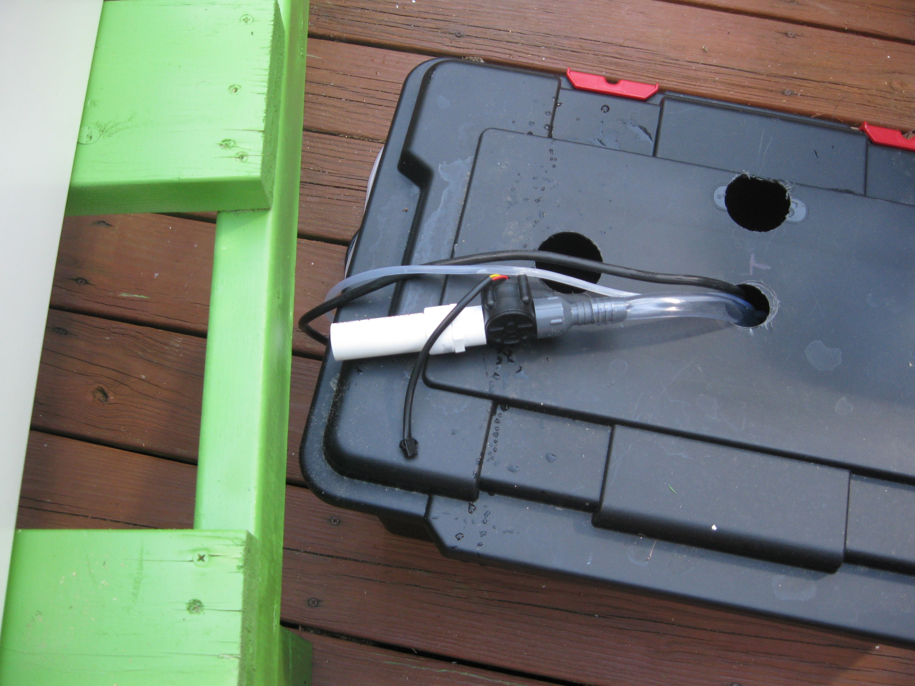
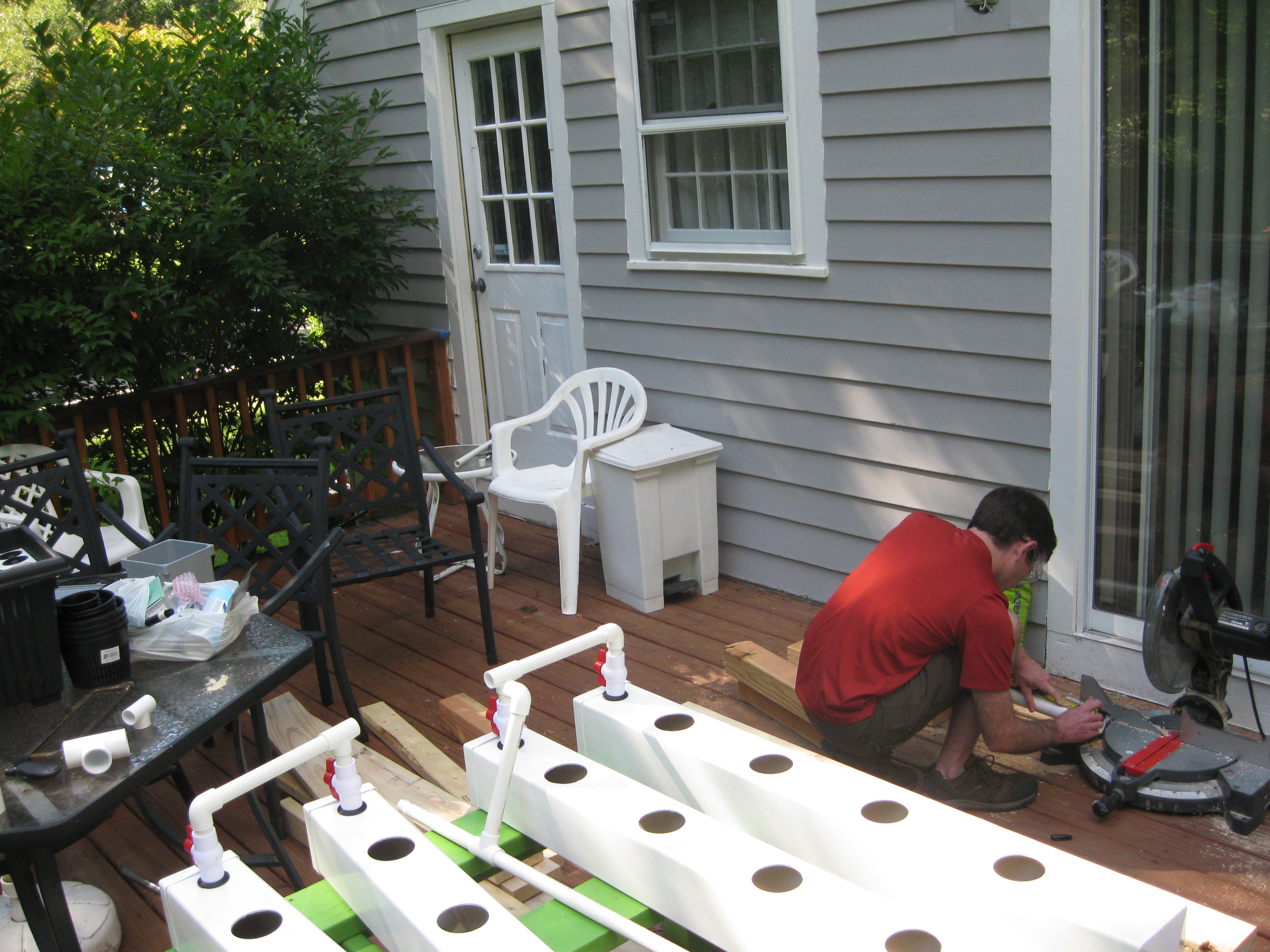
/*
 * To change this template, choose Tools | Templates
 * and open the template in the editor.
 *
 * This is a simple demonstration of how to upload data to vivaplanet using
* from a file
* */

package vivaplanetjava0;

import java.io.BufferedReader;
import java.io.File;
import java.io.FileNotFoundException;
import java.io.FileReader;
import java.io.IOException;
import java.io.OutputStream;
import java.net.HttpURLConnection;
import java.net.URL;
import java.util.ArrayList;
import java.util.List;

import com.google.gson.*;
import com.sun.org.apache.xerces.internal.impl.dv.util.Base64;

import java.util.Calendar;
import java.util.Locale;
import javax.crypto.*;
import javax.crypto.spec.*;

import java.io.BufferedReader;
import java.io.DataOutputStream;
import java.io.InputStreamReader;
import java.net.HttpURLConnection;
import java.net.URL;

import javax.net.ssl.HttpsURLConnection;


/**
 *
 * @author Shane
 */
public class VivaPlanetJava0
{

    /**
     * @param args the command line arguments
     */
    public static void main(String[] args) {
        // TODO code application logic here
        System.out.println("Hello, VivaPlanet");

        SendData();

    }

    /**
     *
     * @return
     */
    public static List<String> getSensorData()
    {
       String dataString = null;
        List<String> list = new ArrayList<String>();
        File file = new File("C:\\Users\\Shane\\Desktop\\test.txt"); //change this...
        BufferedReader reader = null;

        try
        {
            reader = new BufferedReader(new FileReader(file));
            String text = null;

            while ((text = reader.readLine()) != null)
            {
                list.add(text);
                //System.out.println(text);
                dataString = text;
            }
        }
        catch (FileNotFoundException e)
        {
            e.printStackTrace();
        }
        catch (IOException e)
        {
            e.printStackTrace();
        }
        finally
        {
            try
            {
                if (reader != null)
                {
                    reader.close();
                }
            } catch (IOException ex)
            {
                System.out.println("Error 2: " + ex.toString());
            }
        }

        //print out the list
        //System.out.println("Data:" + dataString);

        return list;
    }

    public static void SendData()
    {
        DeviceReport vDeviceReport = new DeviceReport();

        try
        {

           vDeviceReport = getDeviceReport(vDeviceReport);

           System.out.println("Device Report: ");
           System.out.println("Device ID: " + vDeviceReport.getDeviceID());
           System.out.println("Device Address: " + vDeviceReport.getAddress());
           Sensors[] sensor = vDeviceReport.getDeviceSensors();
           int sensorType = -1;
           //check to see which sensor reported the data
           for(int ii=0; ii<4; ii++)
           {
            if(sensor[ii] != null)
            {
                sensorType = ii;
            }
           }

           //sensor type not is predetermined
           System.out.println("Sensor Type: " + sensor[sensorType].getSensorType());
           System.out.println("Sensor Value: " + sensor[sensorType].getValue());
           System.out.println("Sensor Time: " + sensor[sensorType].getReading());

           NotifyServiceQueue(vDeviceReport);

        }
        catch (Exception ex)
        {
            System.out.println("Error 3: " + ex.toString());
        }
        finally
        {
               // put java locking code here and also cleanup code
        }
    }
    public static String DeviceSerialNumer = "17564321";
    private static DeviceReport getDeviceReport(DeviceReport vDeviceReport)
    {
        Sensors[] sensor = new Sensors[4];
        Sensors sensorTemp = new Sensors();

        List<String> sensorData = null;
        try
        {
            // Read the string from a file.
            sensorData = getSensorData();

        }
        catch (Exception ex)
        {
            System.out.println("Error 4: " + ex.toString());
        }


        String tempData = sensorData.get(0);
        System.out.println("String: " + tempData);

        String[] deviceOutput = tempData.split("\\^");

        vDeviceReport.setAddress(deviceOutput[0]);
        vDeviceReport.setDeviceID(DeviceSerialNumer);
        sensorTemp.setSensorType(deviceOutput[3]);
        sensorTemp.setValue(deviceOutput[4]);
        sensorTemp.setReading(deviceOutput[5]);

        switch (deviceOutput[3])
        {
            case "0":
                sensor[0] = sensorTemp; //using the ADC ports to assign sensor type  and the sensor number
                sensor[0].setSensorType("humidity");
                break;
            case "1":
                sensor[1] = sensorTemp; //using the ADC ports to assign sensor type  and the sensor number
                sensor[1].setSensorType("temperature");
                break;
            case "2":
                sensor[2] = sensorTemp; //using the ADC ports to assign sensor type  and the sensor number
                sensor[2].setSensorType("light");
                break;
            case "3":
                sensor[3] = sensorTemp; //using the ADC ports to assign sensor type  and the sensor number
                sensor[3].setSensorType("pH");
                break;
            default:

                break;
        }

        vDeviceReport.setDeviceSensors(sensor);

        return vDeviceReport;
    }

    static void NotifyServiceQueue(DeviceReport device)
    {
        String charset = "UTF-8";  // Or in Java 7 and later, use the constant: java.nio.charset.StandardCharsets.UTF_8.name()
        URL iurl = null;
      try
        {
            iurl = new URL("https://vivaplanetbusservicedev.servicebus.windows.net/hummingbirdqueue/messages");
            Gson gson = new Gson();

            HttpURLConnection sbRequest = (HttpURLConnection)iurl.openConnection();

            //add request header
            sbRequest.setRequestMethod("POST"); // Triggers POST.
            //will expire after 1 hour...
            String resourceUri = "https://vivaplanetbusservicedev.servicebus.windows.net/hummingbirdqueue/messages";
            String keyName = "DevicePolicy";
            String key = "YOMfbmtih/oEERPw3u3ha2wazXR0N2uSFsN61+cKjpM=";

            String cToken =  createToken(resourceUri, keyName, key);
            System.out.println("Token: " + cToken);

            sbRequest.setRequestProperty("Authorization", cToken);

            //send post request
            sbRequest.setDoOutput(true);
            DataOutputStream output = new DataOutputStream(sbRequest.getOutputStream());

            //OutputStream output = sbRequest.getOutputStream();
            String body = gson.toJson(device);
            //byte[] bytes = Encoding.UTF8.GetBytes(body);

            output.write(body.getBytes(charset));
            output.flush();
            output.close();

            int responseCode = sbRequest.getResponseCode();
            System.out.println("\nSending 'POST' request to URL : " + iurl);

            System.out.println("Response Code : " + responseCode);

            BufferedReader in = new BufferedReader(new InputStreamReader(sbRequest.getInputStream()));
            String inputLine;
            StringBuffer response = new StringBuffer();

            while ((inputLine = in.readLine()) != null) {
                    response.append(inputLine);
            }
            in.close();

            //print result
            System.out.println(response.toString());

        }
        catch (Exception ex)
        {
            System.out.println("Error 7: " + ex.toString());
        }
    }

    private static String createToken(String resourceUri, String keyName, String key)
    {
        String charset = "UTF-8";
        String sasToken = null;
        Calendar currentTime = Calendar.getInstance(Locale.ENGLISH);
        String expiry = "1440710529"; //String.valueOf(currentTime.getTimeInMillis()/1000 + 3600 );
        System.out.println("Time:" + expiry.toString());

        try
        {
            String stringToSign = java.net.URLEncoder.encode(resourceUri, charset) + expiry.toString();
            byte[] bStringToSign = stringToSign.getBytes(charset);

            System.out.println("strToSgn:" + stringToSign);

            byte[] bKey = key.getBytes(charset);
            System.out.println("bKey:" + new String(bKey, charset));

            Mac hMac = Mac.getInstance("HmacSHA256");
            SecretKeySpec seed = new SecretKeySpec(bStringToSign, "HmacSHA256");
            hMac.init(seed);

           // System.out.println("seed:" + new String(seed, charset));

            byte[] hStringToSign = hMac.doFinal(bStringToSign);
            System.out.println("hmac:" + new String(hStringToSign, charset));
            String signature = org.apache.commons.codec.binary.Base64.encodeBase64String(hStringToSign);
            System.out.println("signature:" + signature);

            sasToken = String.format(Locale.getDefault(),
                                           "SharedAccessSignature sr=%s&sig=%s&se=%s&skn=%s",
                                           java.net.URLEncoder.encode(resourceUri,charset),
                                           java.net.URLEncoder.encode(signature, charset),
                                           expiry,
                                           keyName);
        }
        catch(Exception ex)
        {
               System.out.println("Error 8: " + ex.toString());
        }

        return sasToken;
    }
    final protected static char[] hexArray = "0123456789ABCDEF".toCharArray();
    public static String bytesToHex(byte[] bytes)
    {
        char[] hexChars = new char[bytes.length * 2];
        for ( int j = 0; j < bytes.length; j++ ) {
            int v = bytes[j] & 0xFF;
            hexChars[j * 2] = hexArray[v >>> 4];
            hexChars[j * 2 + 1] = hexArray[v & 0x0F];
        }

        return new String(hexChars);
    }
}
Moving on, some of the final touches were added to the NFT grow system. I ordered more PVC ball valves, and they arrived in the last two weeks and the other day I did some work on the system. I needed an additional valve to implement a drain system in the input manifold of the grow system. I placed an additional valve (valve number 5) in the input manifold to allow for a drain, it works by shutting off the pump system closing the valves on each of the 4 rows then open the 5th valve then turn the pump back on to pump out the water. The idea behind implementing this into the input manifold is to allow for simple draining of waste water without having to remove the reservoir. Additionally I set up the reservoir and ran the pump cable and air tubing out of the reservoir.
![]()
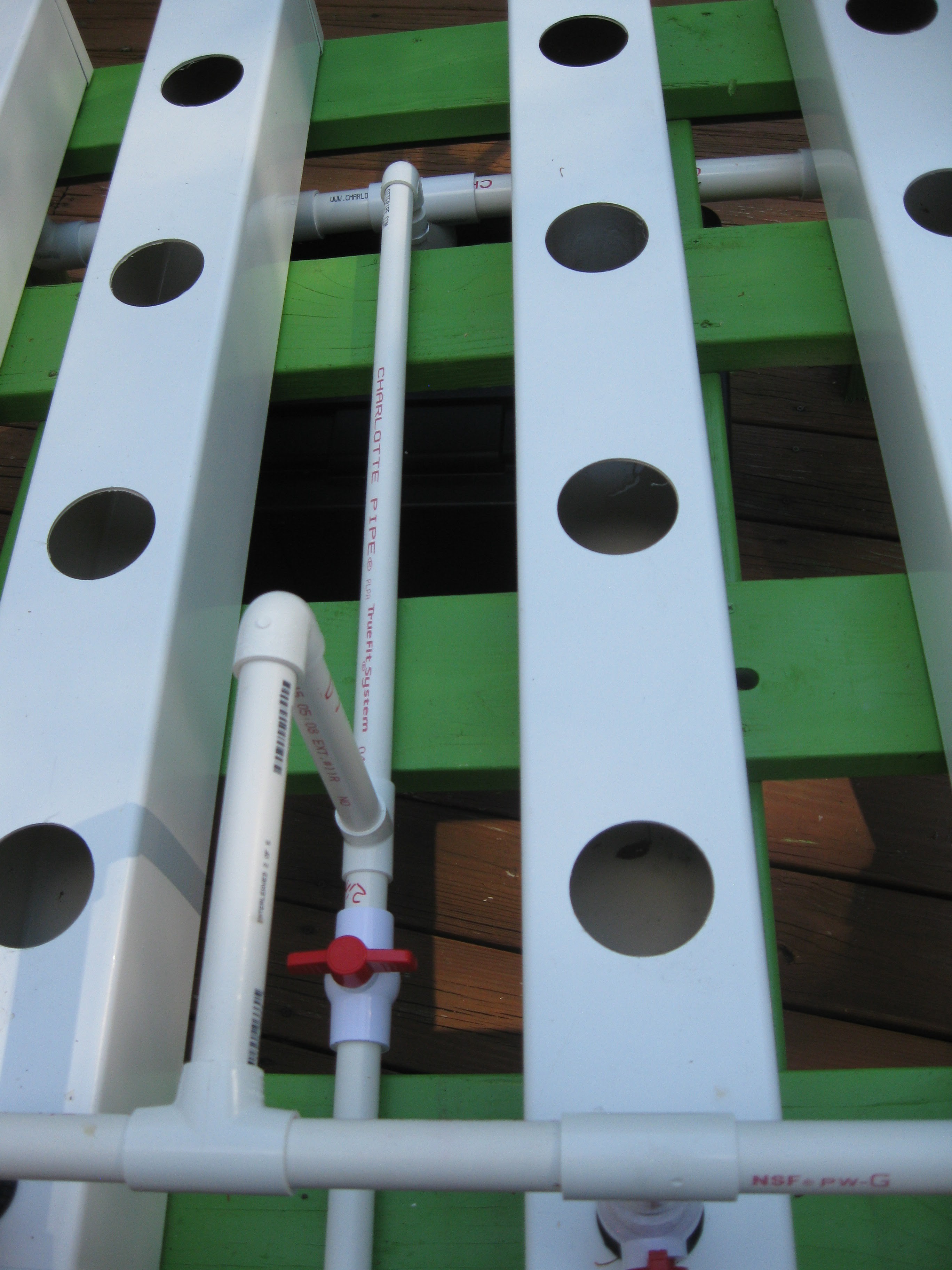
Close up of manifold valve addition:
![]()
Another view
![]()
Shot from the other side:
![]()
Reservoir work
![]()
Another view
![]()
Again moving on, I've been taking good care of the plants I plan on installing into the NFT grow system. In a previous log I talked about how I created plants in a water culture cloning bucket, well those plants have been going for about 3 weeks so far and doing quite well for the most part. When I started them up in the cloner I was using the root boosting supplement from general hydroponics, in the last few weeks I have been using general hydroponics Maxigrow nutrients. The are a simple power nutrient for vegetative growth, easy to use because its all in one verse the more advances nutrients I will be using in the NFT system. Most of the plants have great root growth all but the strawberries, I have to look into more about them to find out why they are not taking.
![]()
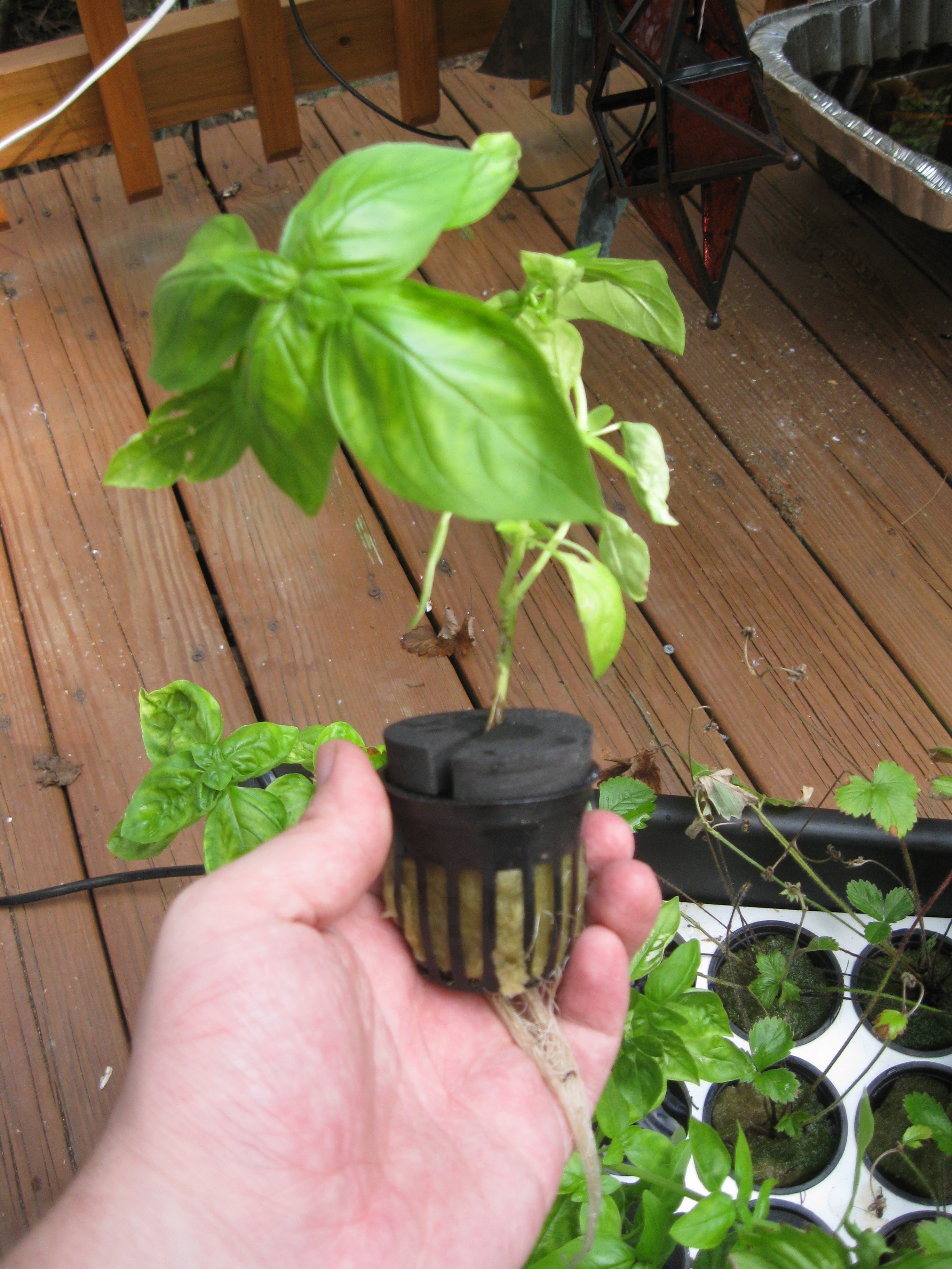
The basil plants have been doing quite well at adapting to hydro, I stated before that I started them as cutting in a glass of water by the window and they had roots to begin with, anyways they are doing really well!
![]()
The peppers finally got some roots, I checked them at an earylier date and they hadn't produced any roots. I read online that pepper plants take longer to germinate even when being made from cuttings (pepper seeds take longer than others to germinate) . Since I started adding the MaxiGro the cloner bucket the peppers stated to root, I read online that to get peppers to root vegative growth solution is recommended since they take longer to germinate.
![]()
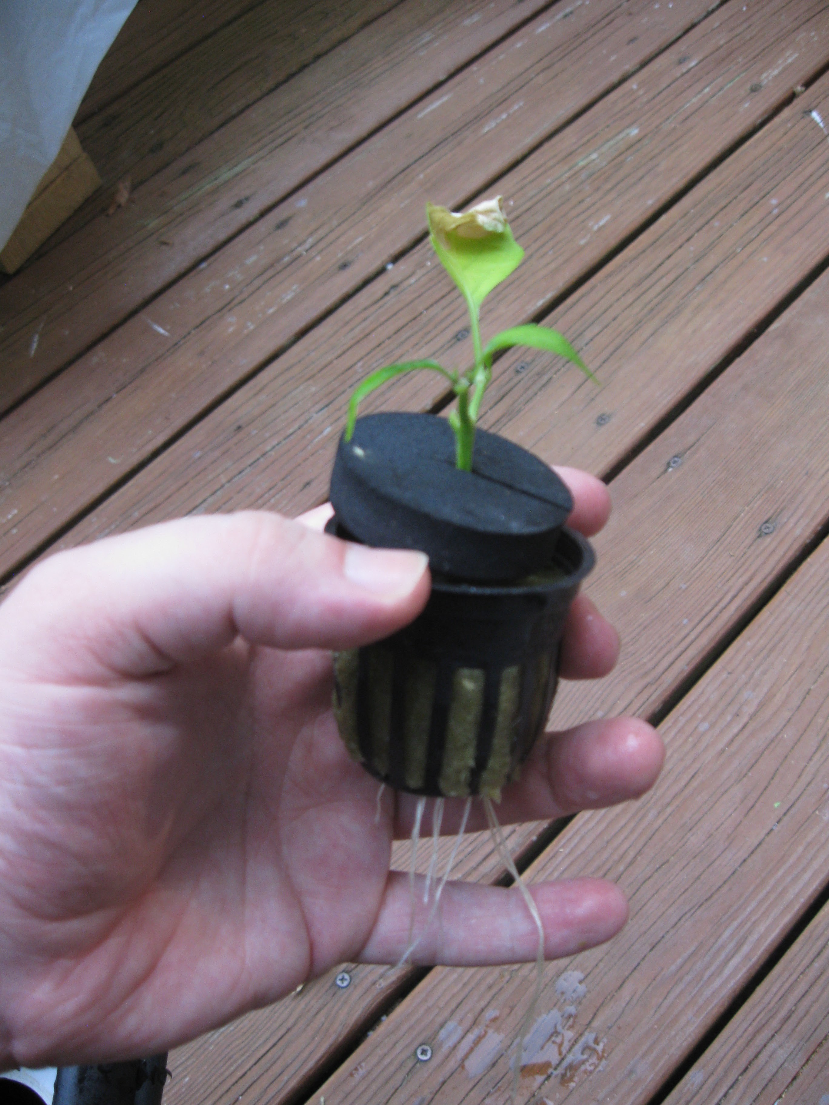
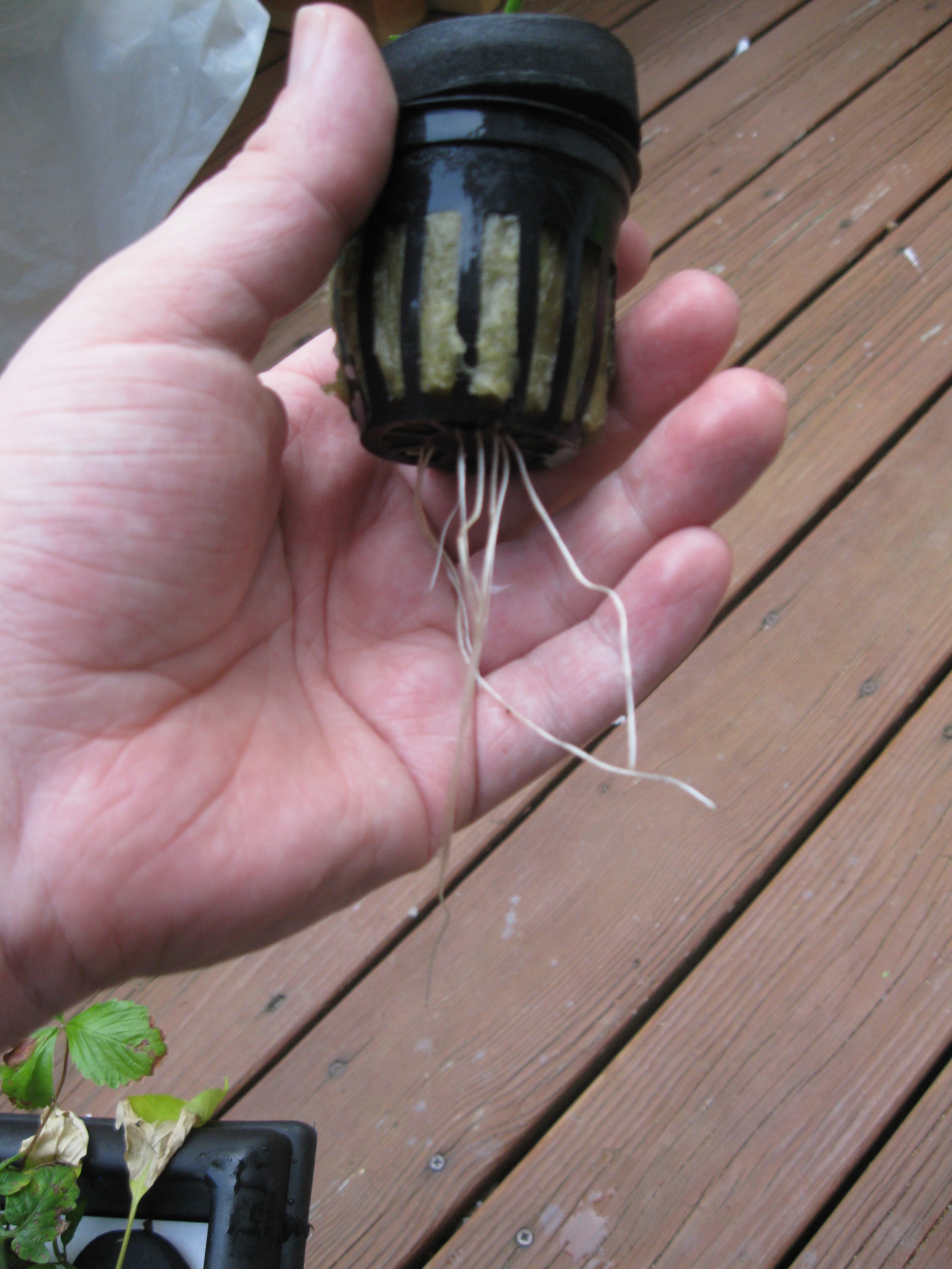
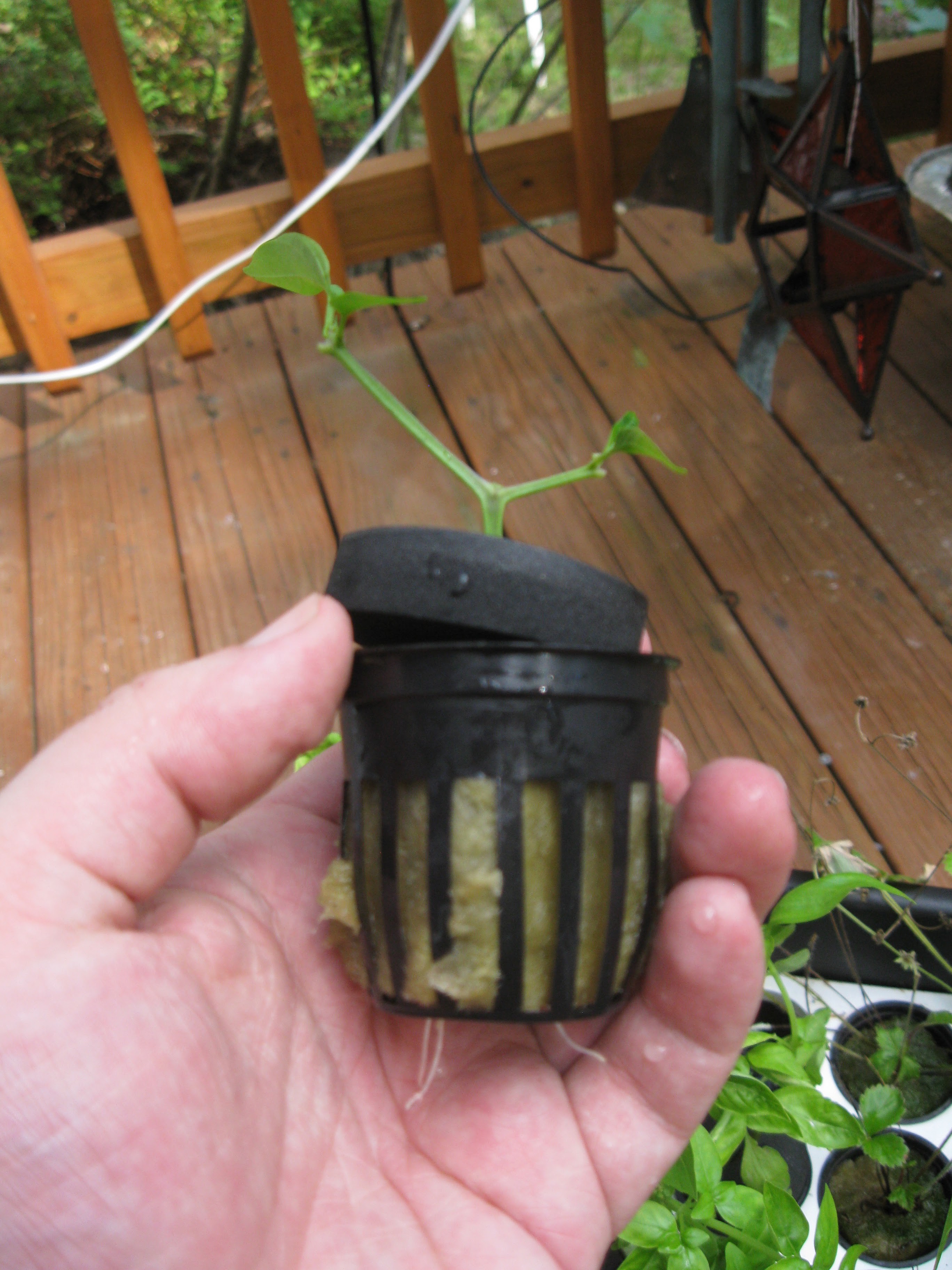
The tomato plant is doing very well too, the plant was made from a cutting of a potted plant, so far the plant has excellent root growth, roots are coming out the sides and bottom of the rockwool cube. I have high hopes for this plant when I install it in the NFT grow system.
![]()
Thats all for now, expect more logs in the coming days, its time to buckle down and get going, good luck to everyone, semi-finals go!
-
Quarterfinals and Stage 2 Submission!
08/17/2015 at 15:55 • 0 commentsI am pleased to announced that I have everything for the next stage of the prize subitted!!
You can view my video on youtube here:
You can View my System Design Document on Google Docs
https://docs.google.com/document/d/1IXcoCZAEUiCCFRzxCEFl9DJrIT8ejn9sYGAsC8lhNkU/edit?usp=sharing
Open Source Licenses related to the project
https://docs.google.com/document/d/1EE3hQ9SbHJR79v5ZPckmglshI-BAw0UKrCl2D9yt2_w/edit?usp=sharing
I have to say the support for this project by the community has been a lot more than expected, and I thank everyone for their support! Now I am all in so expect much more to come, stay tuned!!!!!
-
NFT Progress: Manifold installation
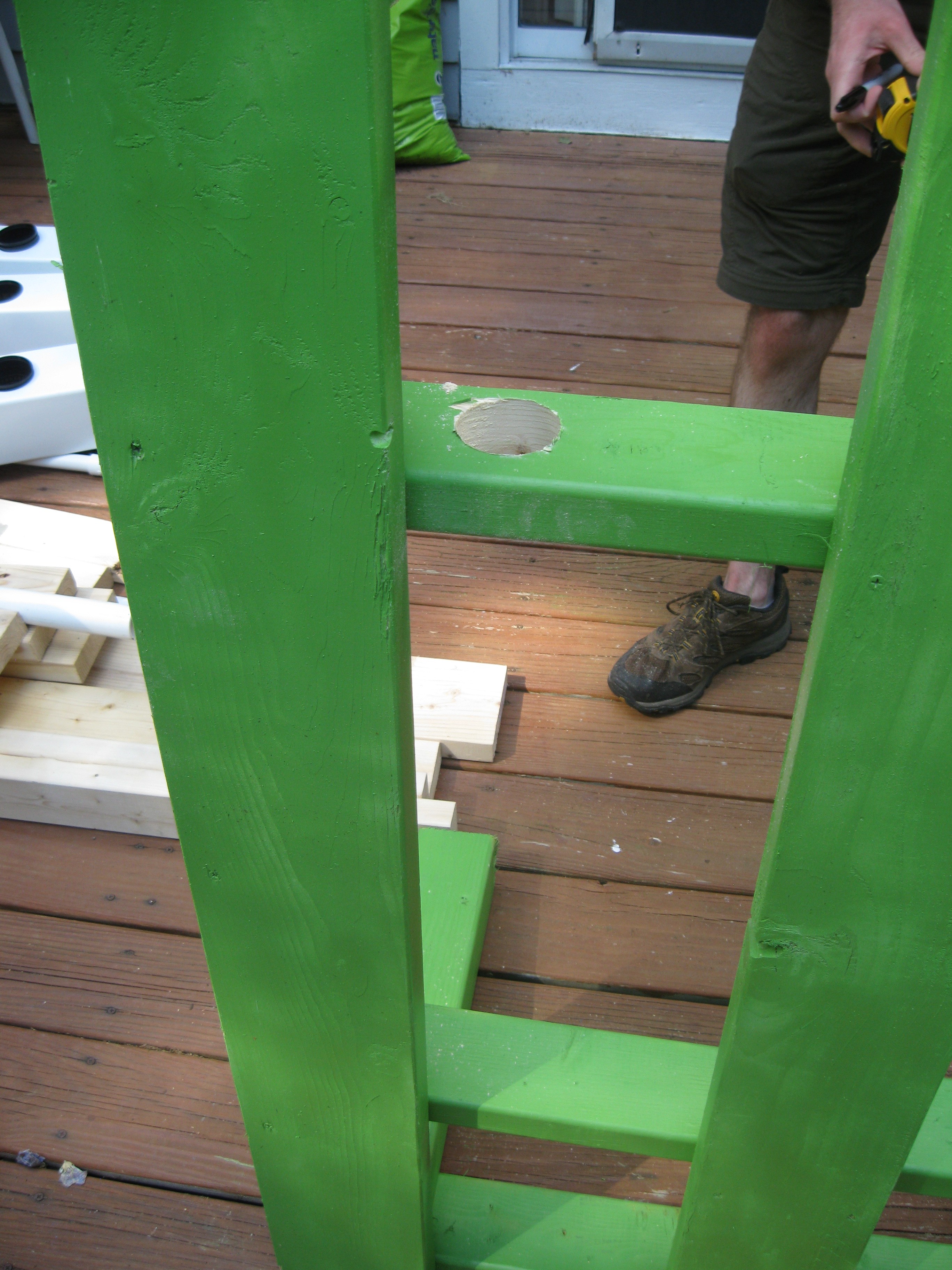
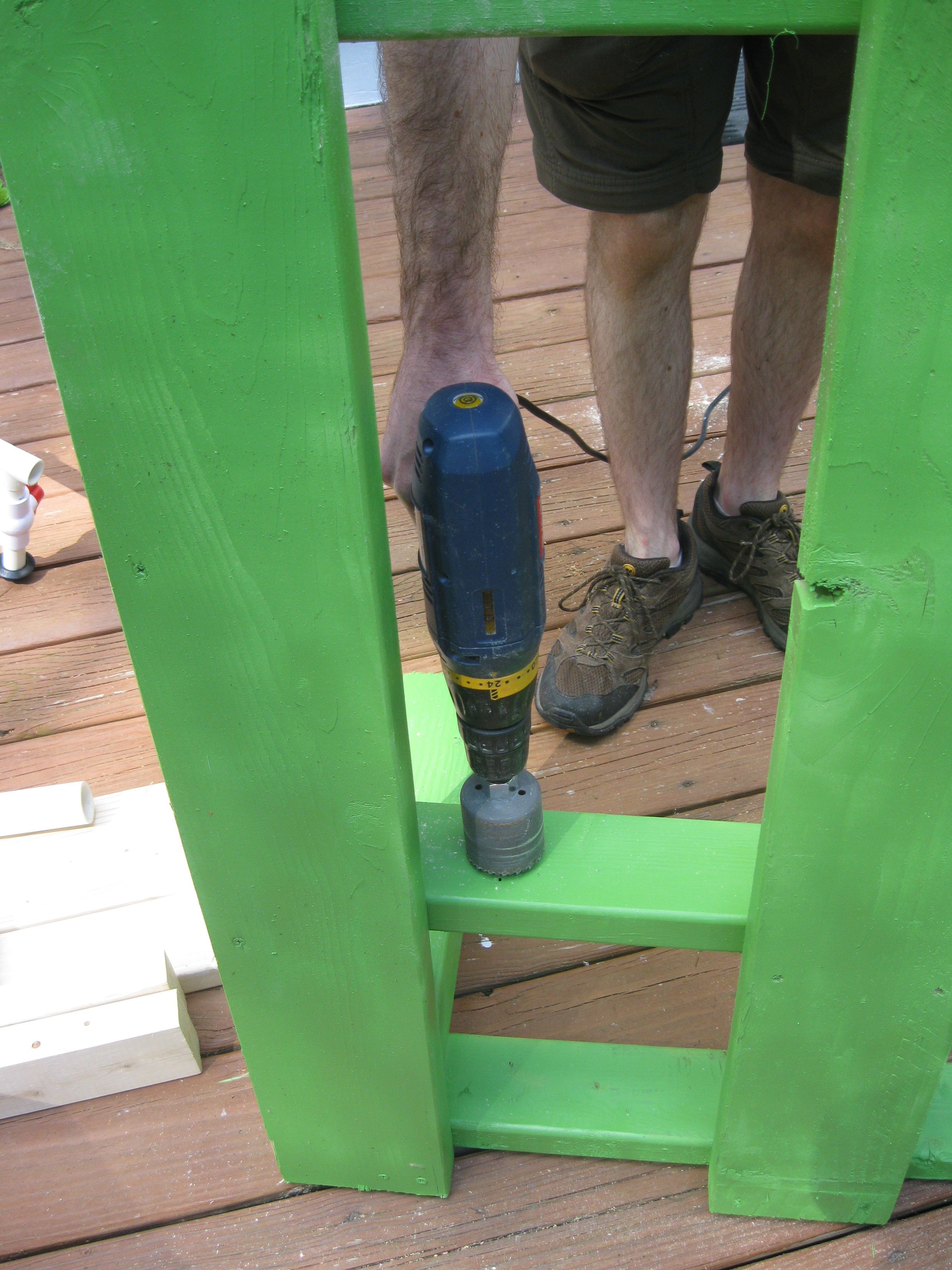
08/12/2015 at 22:50 • 0 commentsSo this last week a lot of progress was made towards completing the NFT grow system that HydroPWNics will be implemented on. Most specifically this past week was dedicated to finishing the water manifolds, drilling holes in the posts for manifolds, and installing the posts and manifolds assembled into the frame.
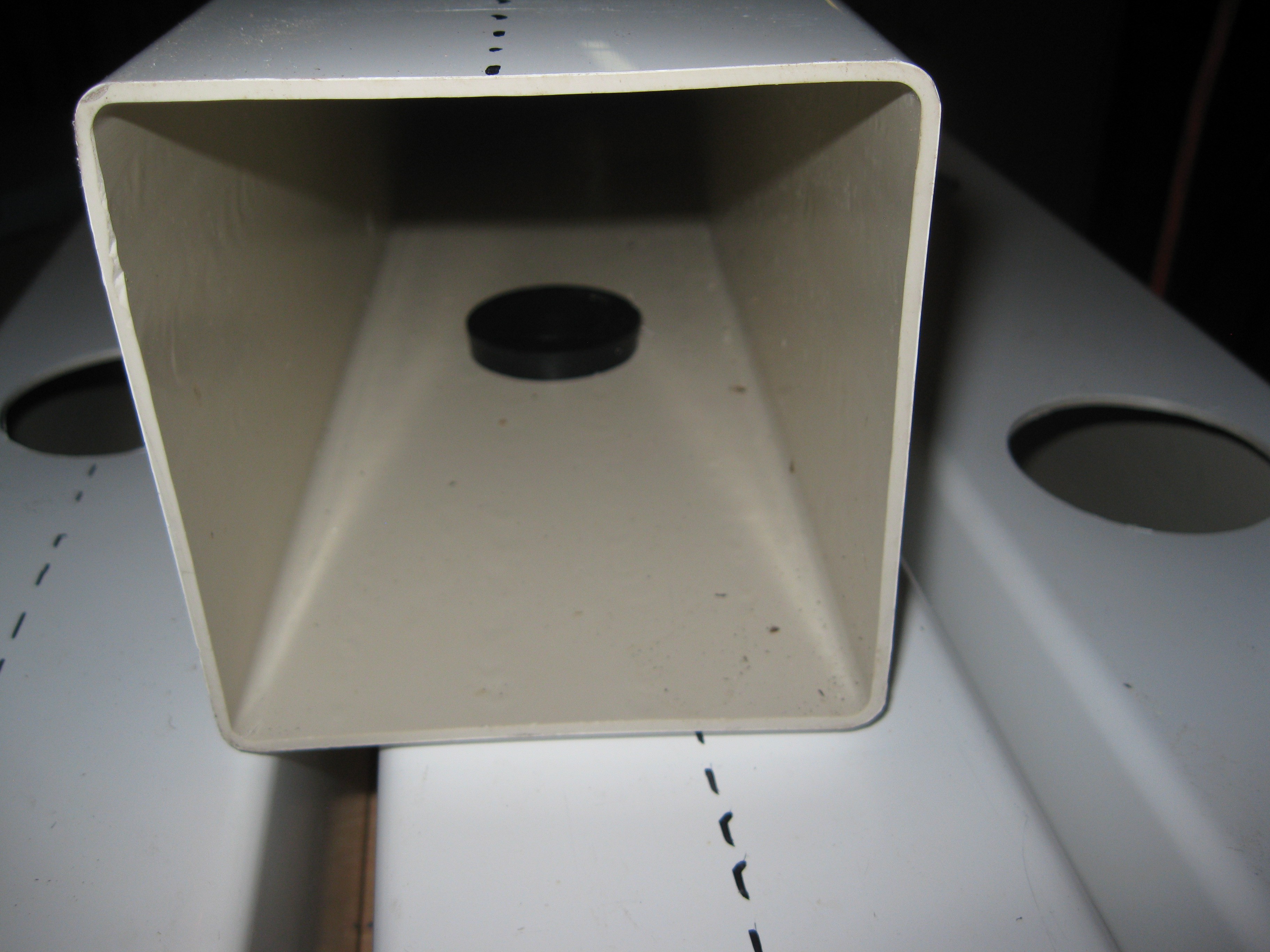
The posts, parts, and partially assembled manifolds were brought over to Technocopia hackerpsace for drilling. To connect the manifolds to the fence posts holes had to be drilled for the uniseal gaskets talked about in the last update. The gasket makea tight seal between the hole, fencepost, and PVC pipe that is water tight. This method also allows for adjustments to be made and some flexibility when assembling. Also at the space the holes for pipes and manifolds were drilled into the reservoir.
![]()
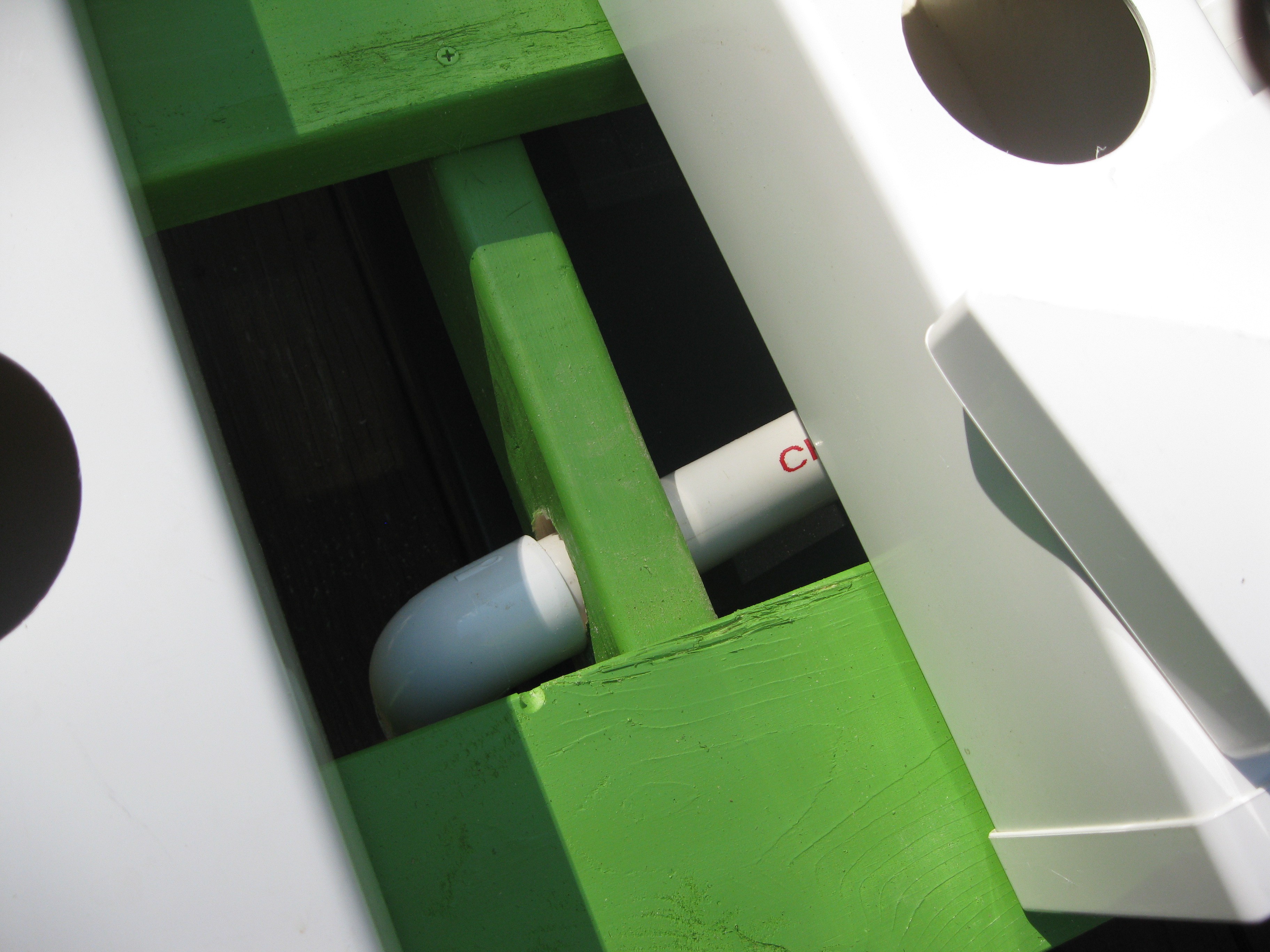
Drain manifold uniseal installed
![]()
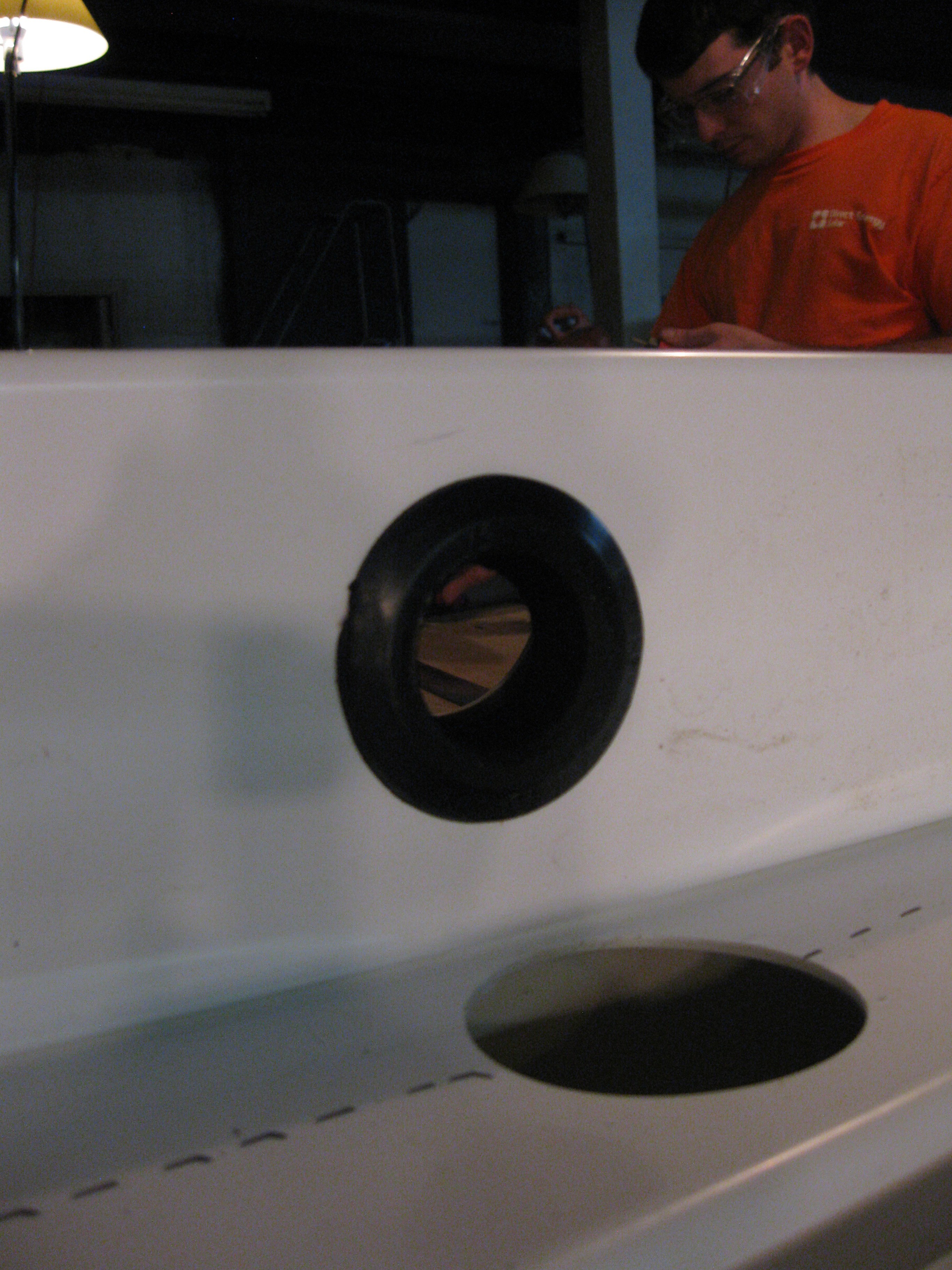
Outer view of drain manifold uniseal, also Will giving into his screen addiction
![]()
Will Getting ready to drill the reservoir holes
![]()
Next big chunk of work was done a few days after the day at the hackerspace, this work was done on the frame and general assembly of the whole unit. The frame was drilled to fit the drain manifold tightly between the top of the frame and top of the reservoir (about 8 inches of clearance). After the holes were drilled it was only a bit of eyeballing and measuring to figure out the dimensions of the pipe sections, we cut them fast on a chop saw and assembled/installed it into the frame. The pictures tell a much better story:
Hole drilled in frame for drain manifold, 2" hole for 1 1/4 inch pipe, left it with enough slack to be moved around some.
![]()
Drilling the second hole in the frame for the drain manifold.
![]()
Testing out cut pipe
![]()
Assembling the manifold within the frame
![]()
Working out on the deck
![]()
More assembly of the drain manifold
![]()
One side assembled and installed
![]()
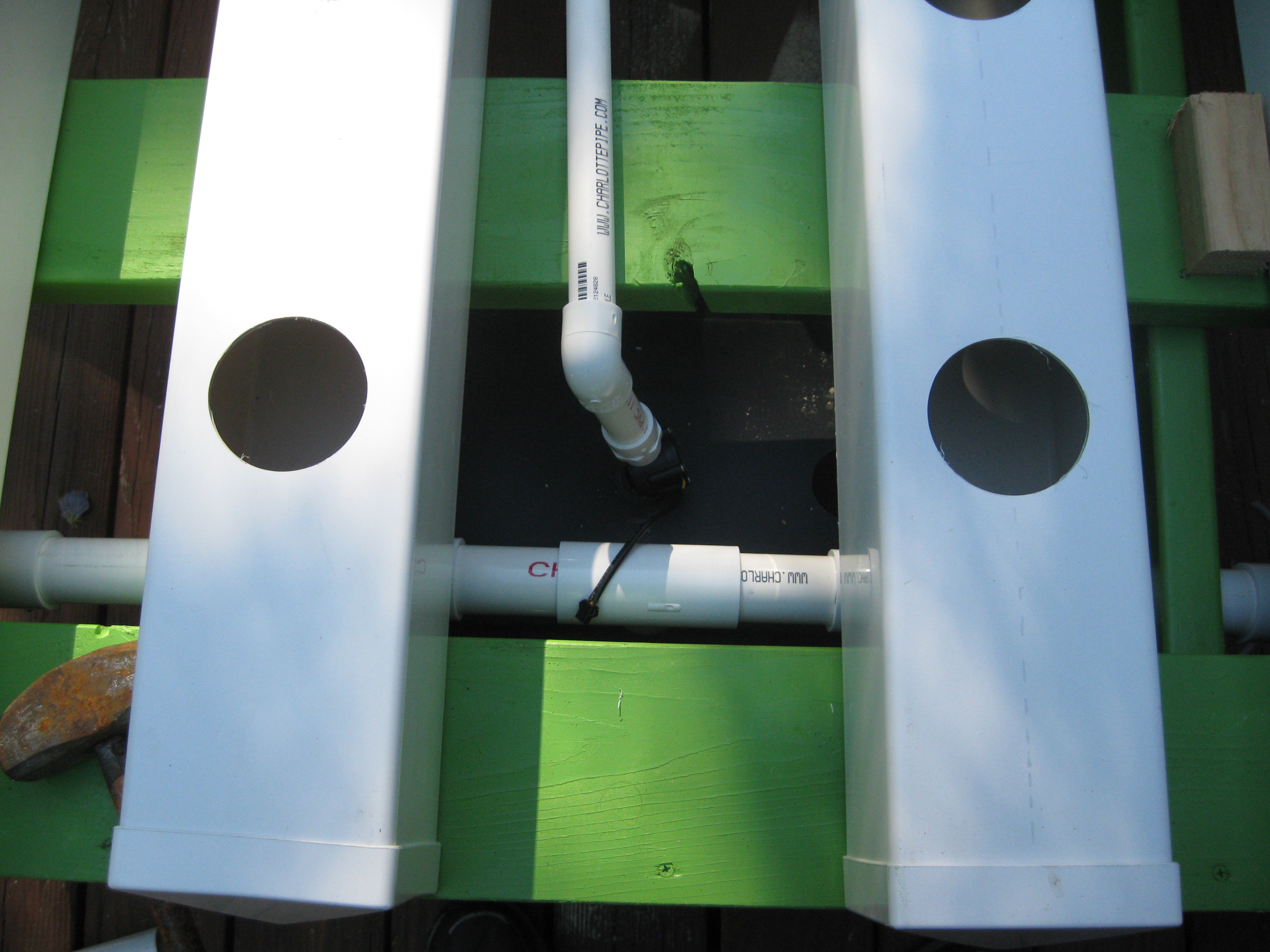
Close up of drain manifold in frame, connected to two fence post rows.
![]()
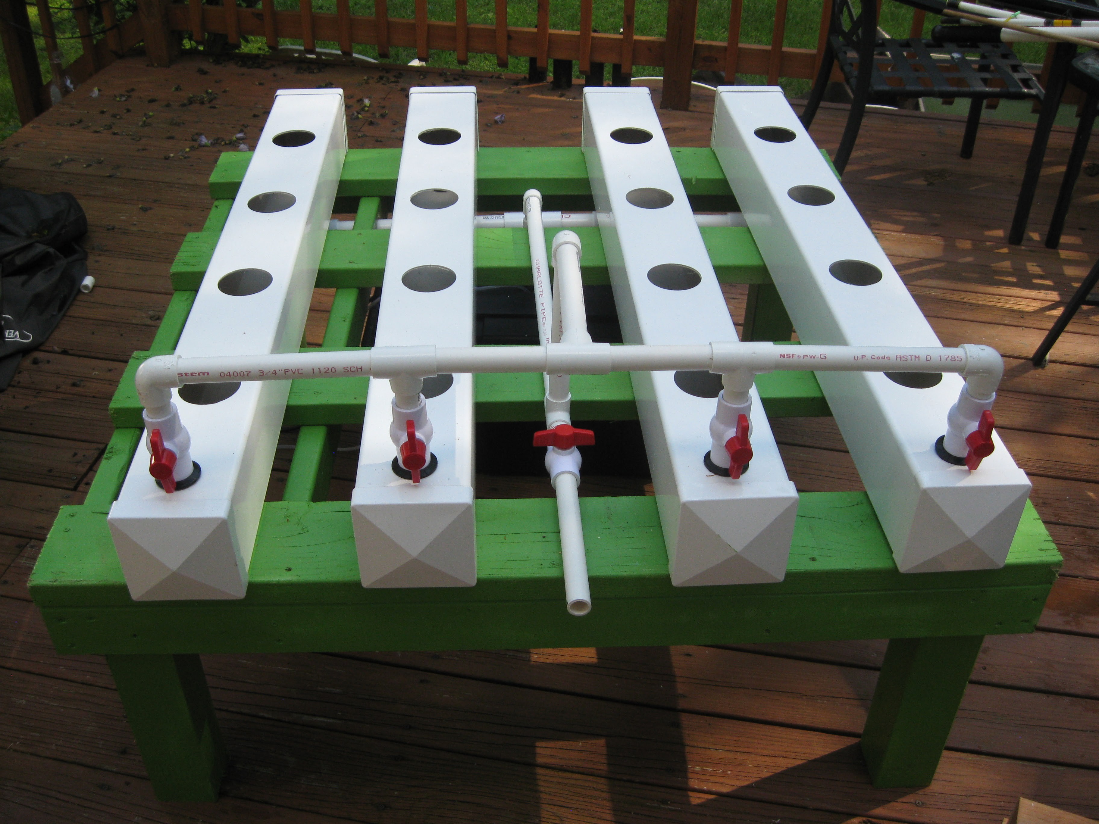
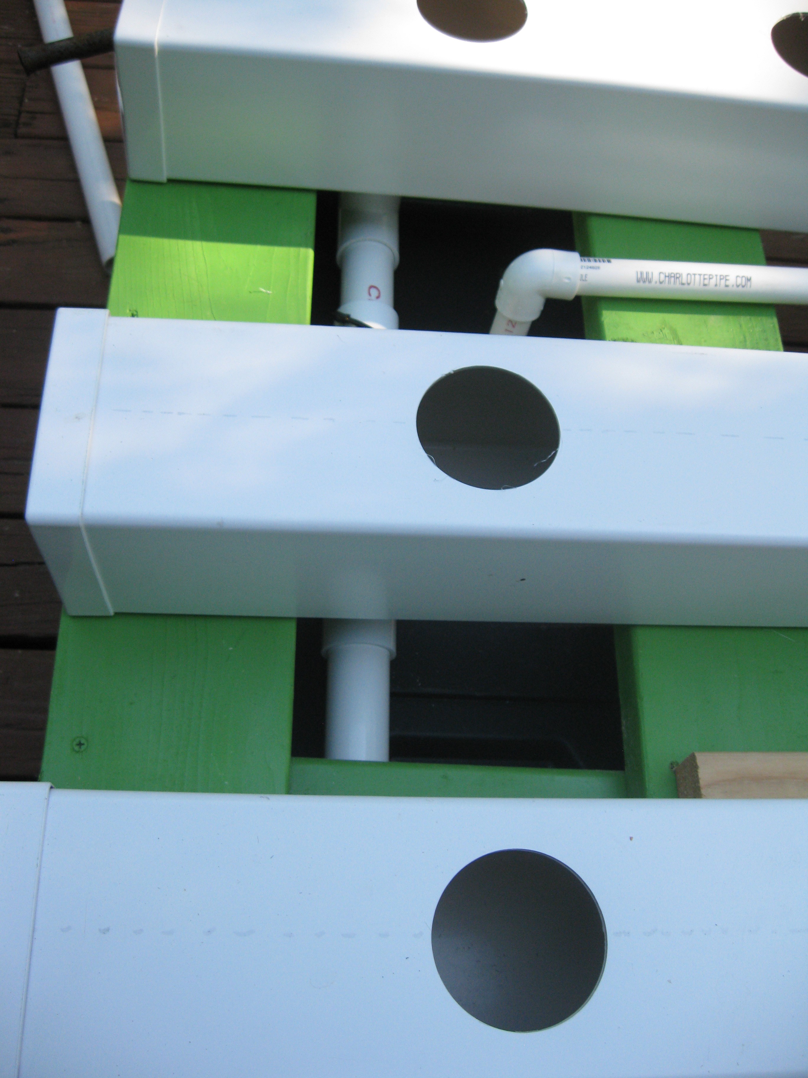
Another view of the drain manifold within the frame and the input manifold pipe between the posts.
![]()
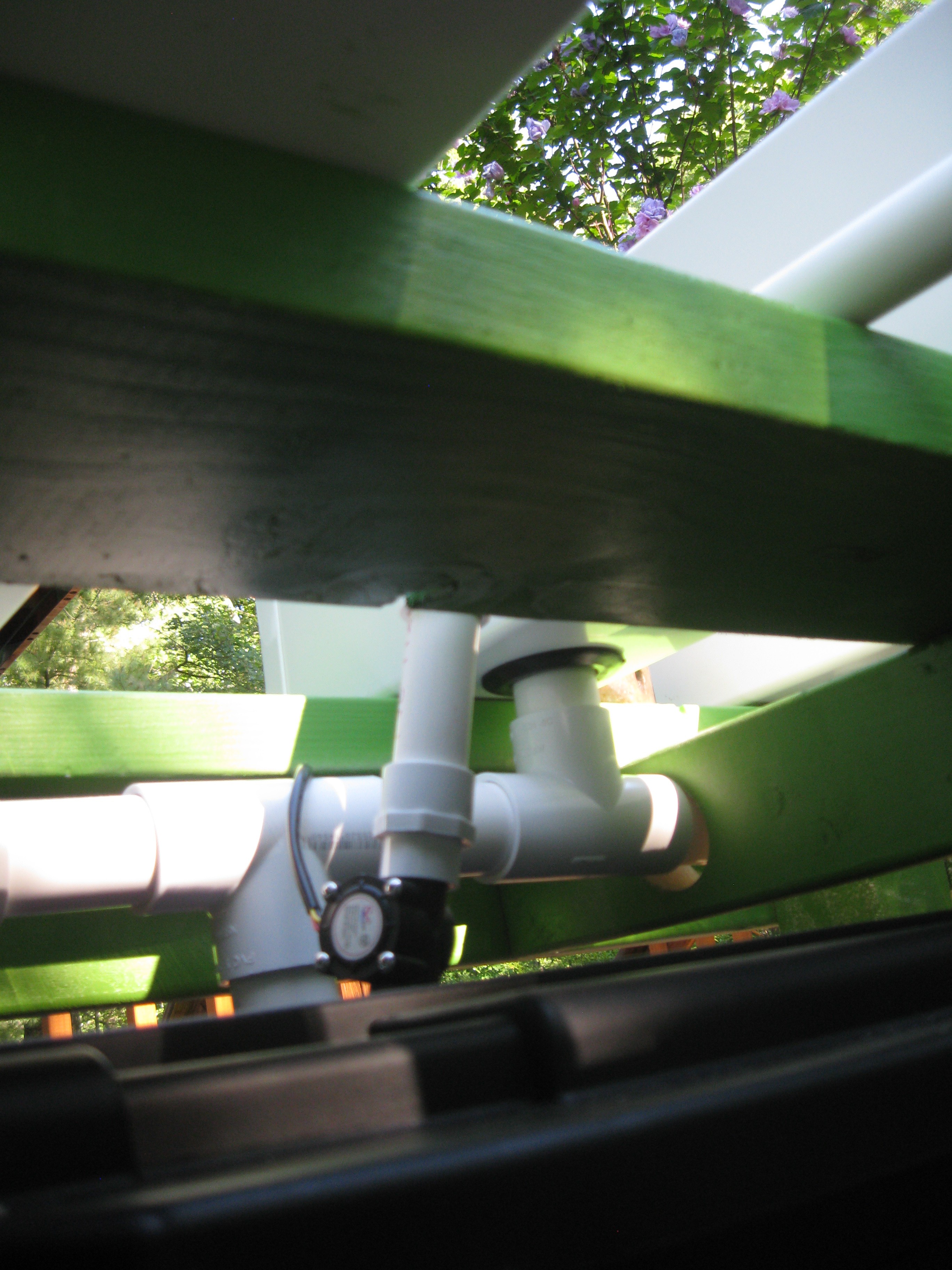
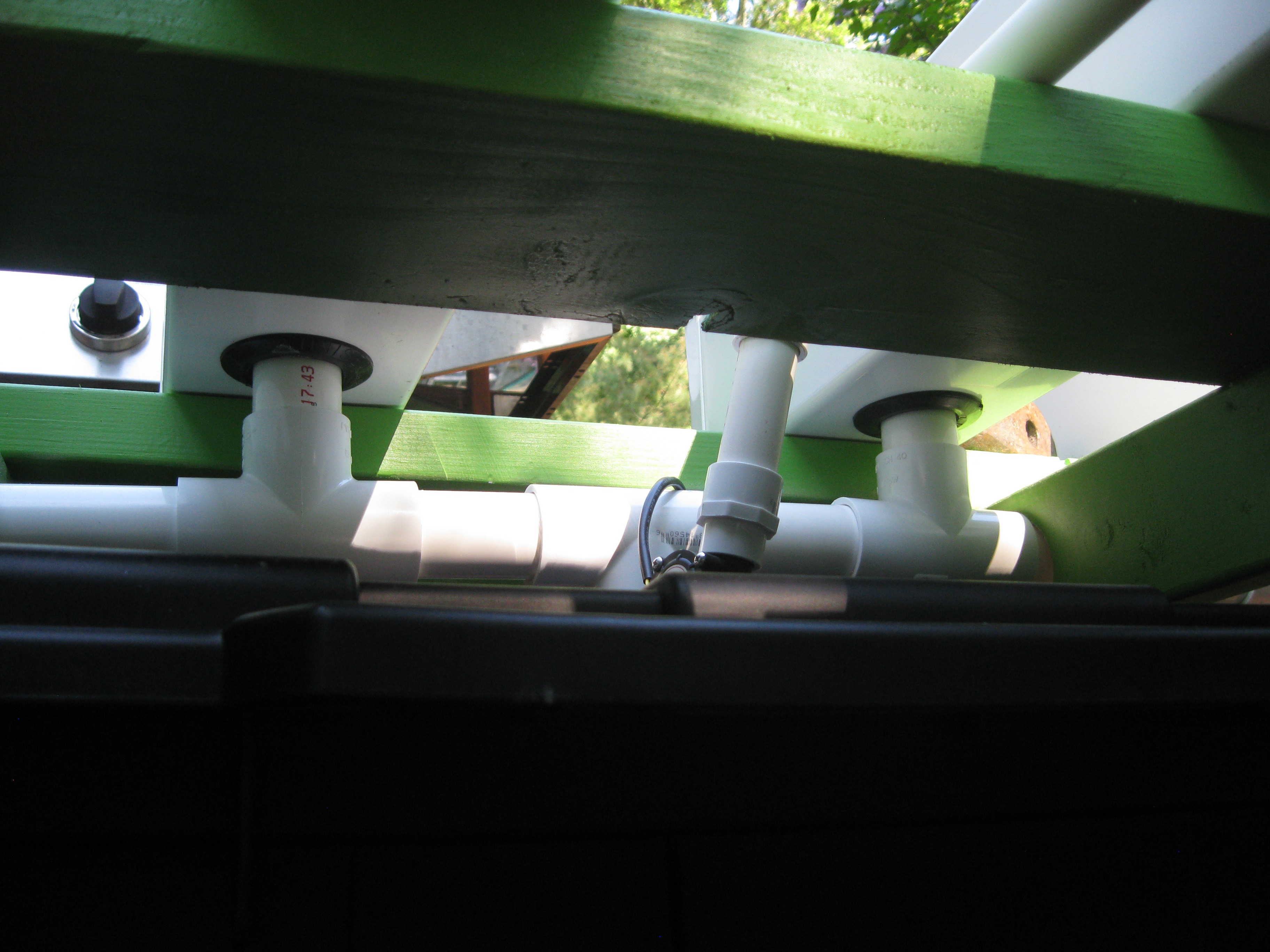
Underneath view of drain manifold installation/assembly
![]()
Better view of drain manifold from underneath feeding into the storage bin reservoir
![]()
A view of the outer ends of the manifold (right angle instead of T)
![]()
Lining up the posts after finishing the manifold installation/assembly.
![]()
All cleaned up and put out of the way until the next build day
![]()
Now its just a matter of time, waiting for the plants to mature in the cloner and a few more parts for a water drainout option and this system will be up and running. The next step will be finishing the HydroPWNics hardware and electronics and deploying it on this system. Stay tuned for more!
-
Water Circulation Parts and Components!
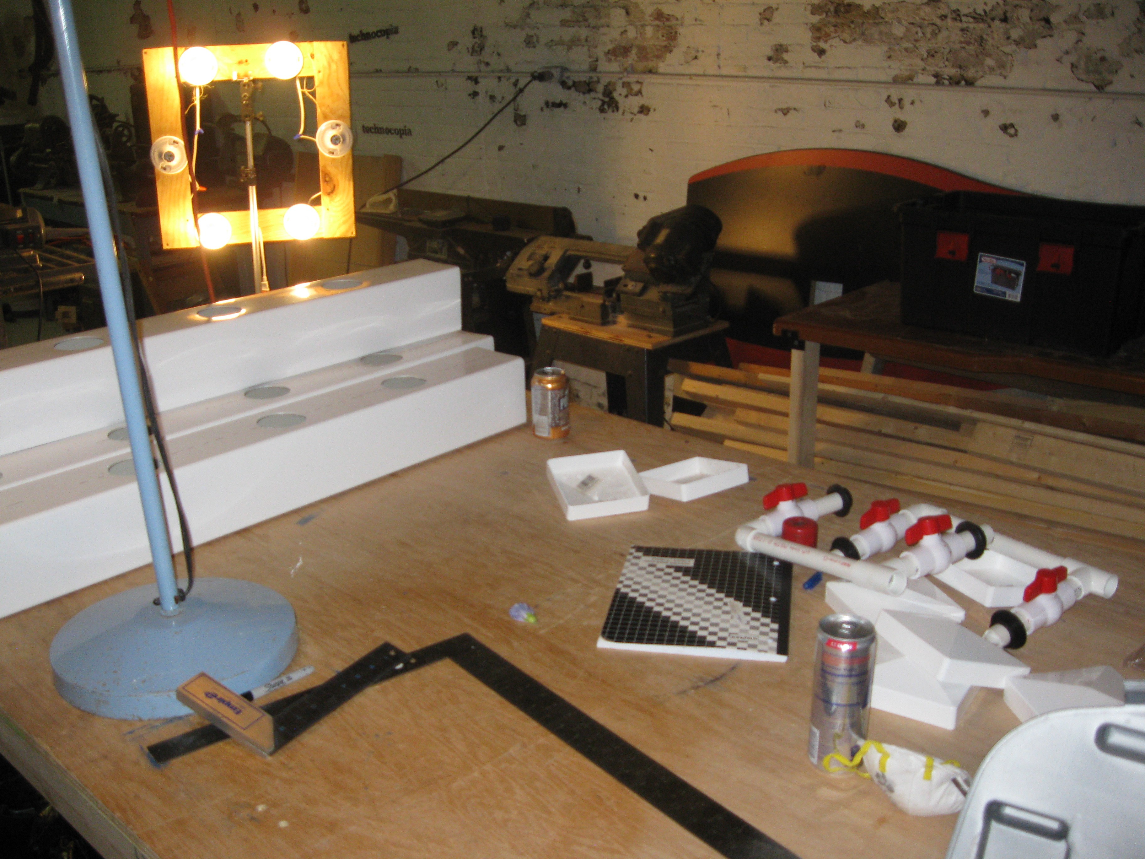
08/11/2015 at 17:03 • 0 commentsPart of HydroPWNics is building a Nutrient Film Technique grow system, this post is mostly about the various parts I made for the NFT grow system I've been working on for the project. Also if you wish to build your own version of this cheap NFT setup I made a separate project page and will be adding pictorial instruction to it to help folks build their own! The other page wont be getting project logs and updates like this one, its mostly to cut down on clutter and be a standalone guide. Project page yo build your own NFT: https://hackaday.io/project/7116-low-cost-nft-hydroponic-garden-under-250
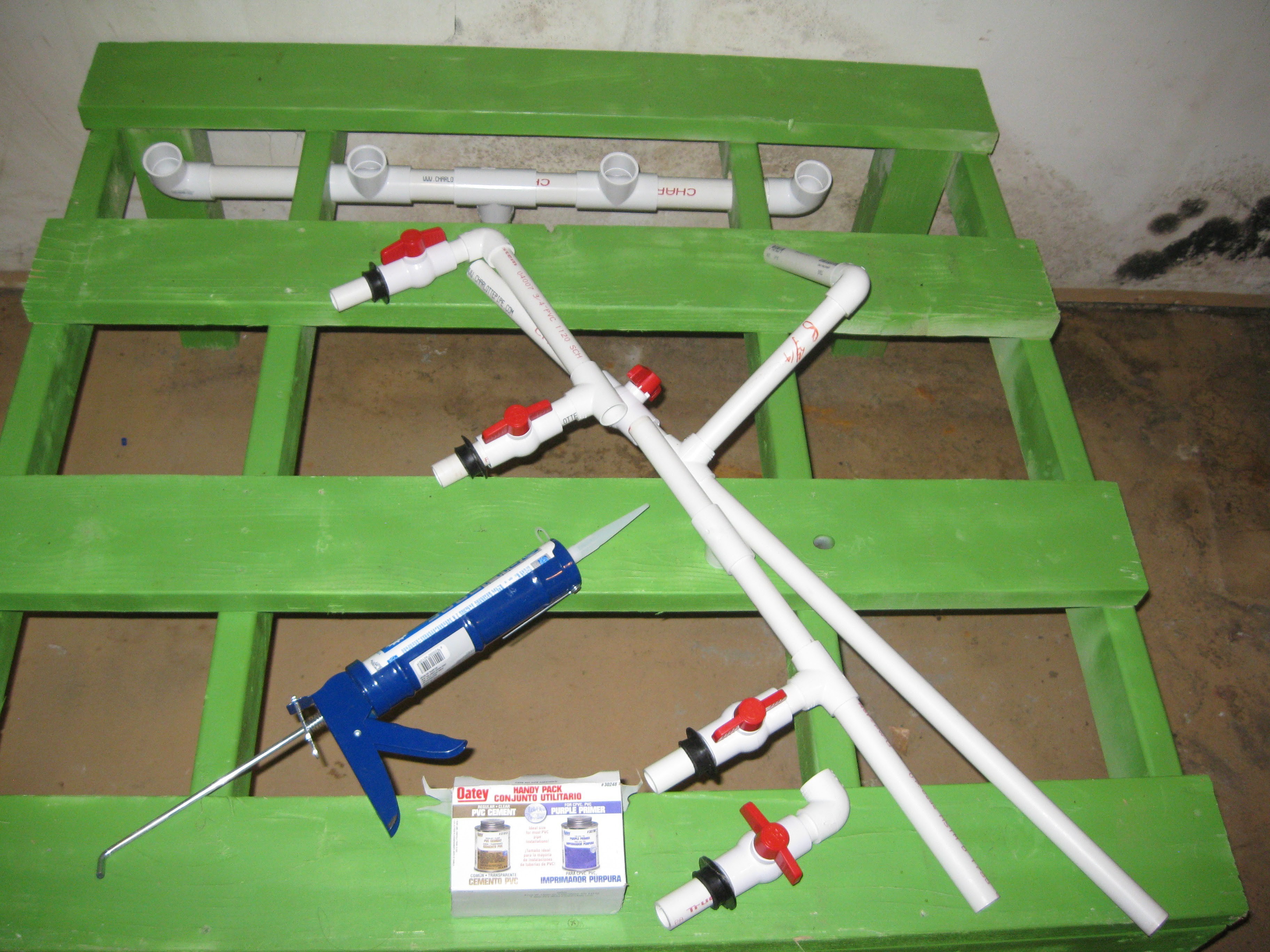
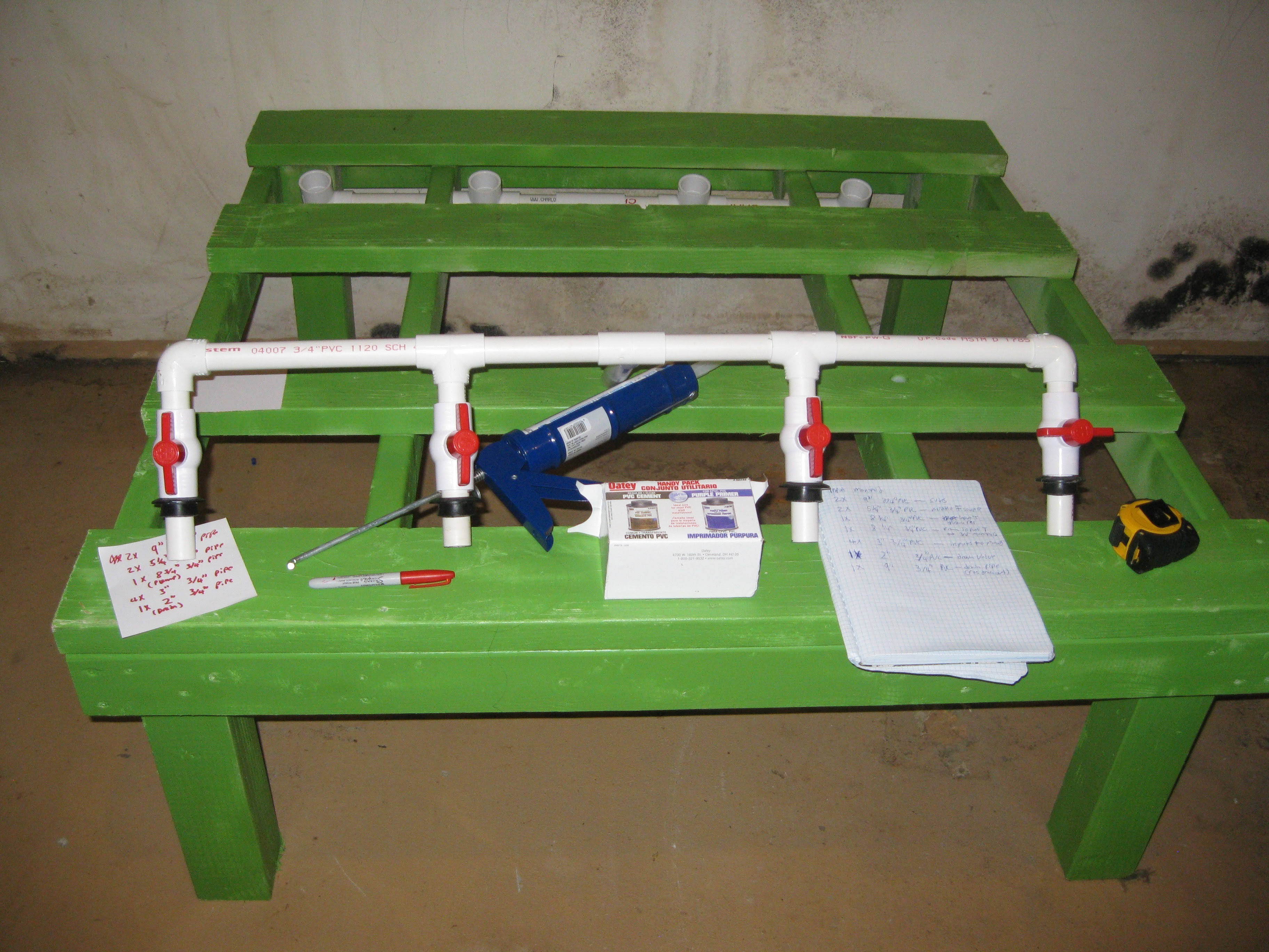
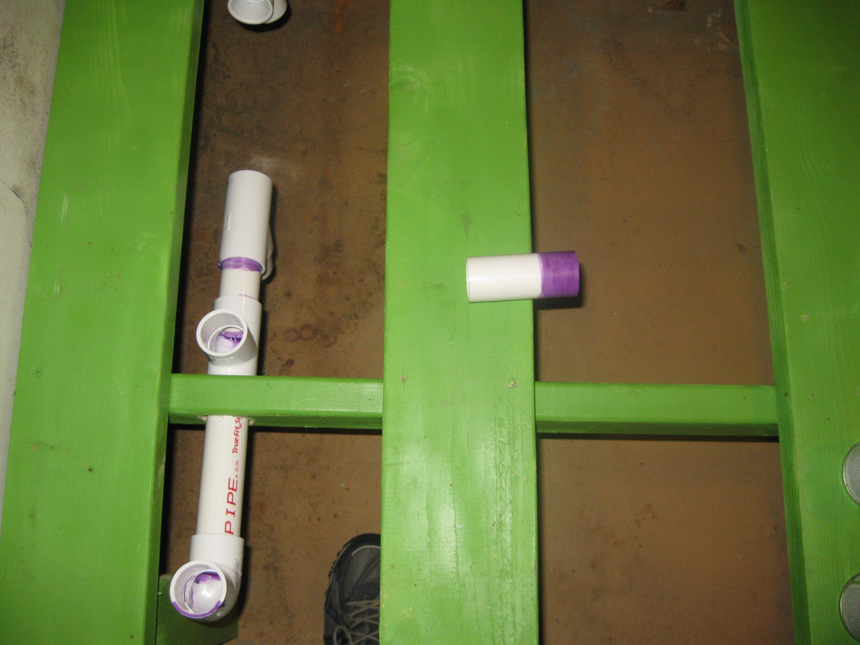
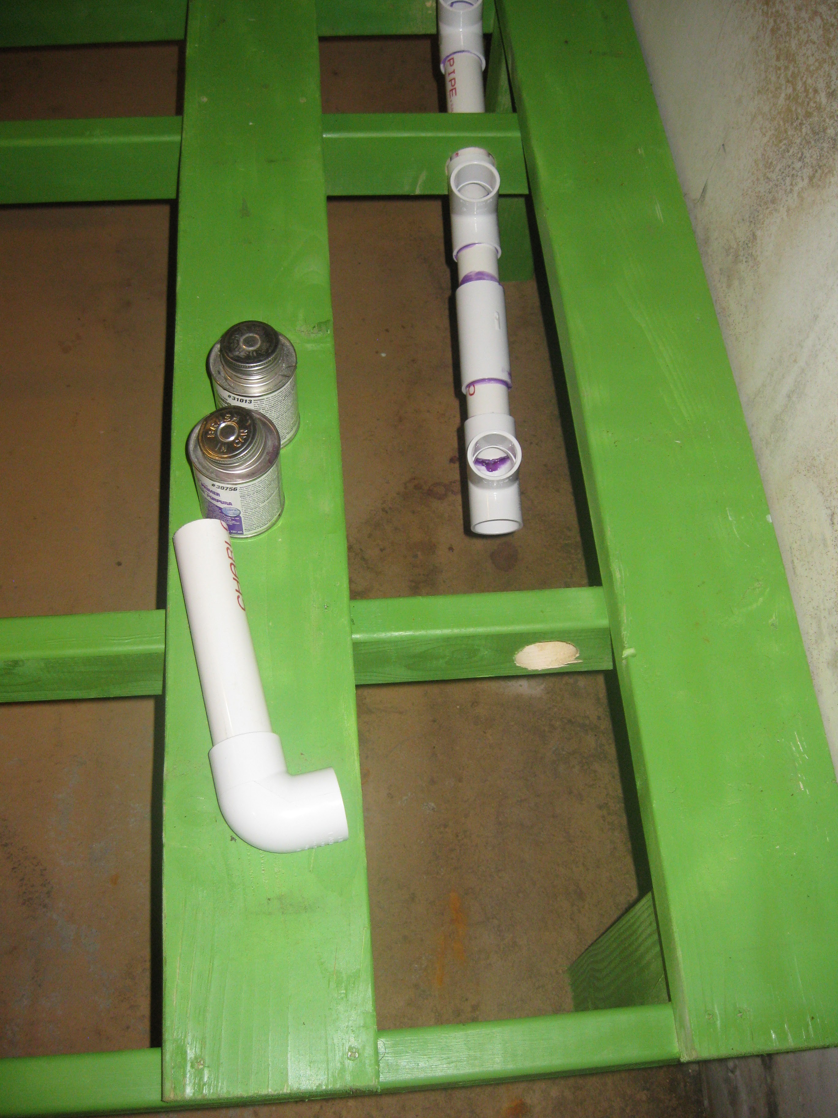
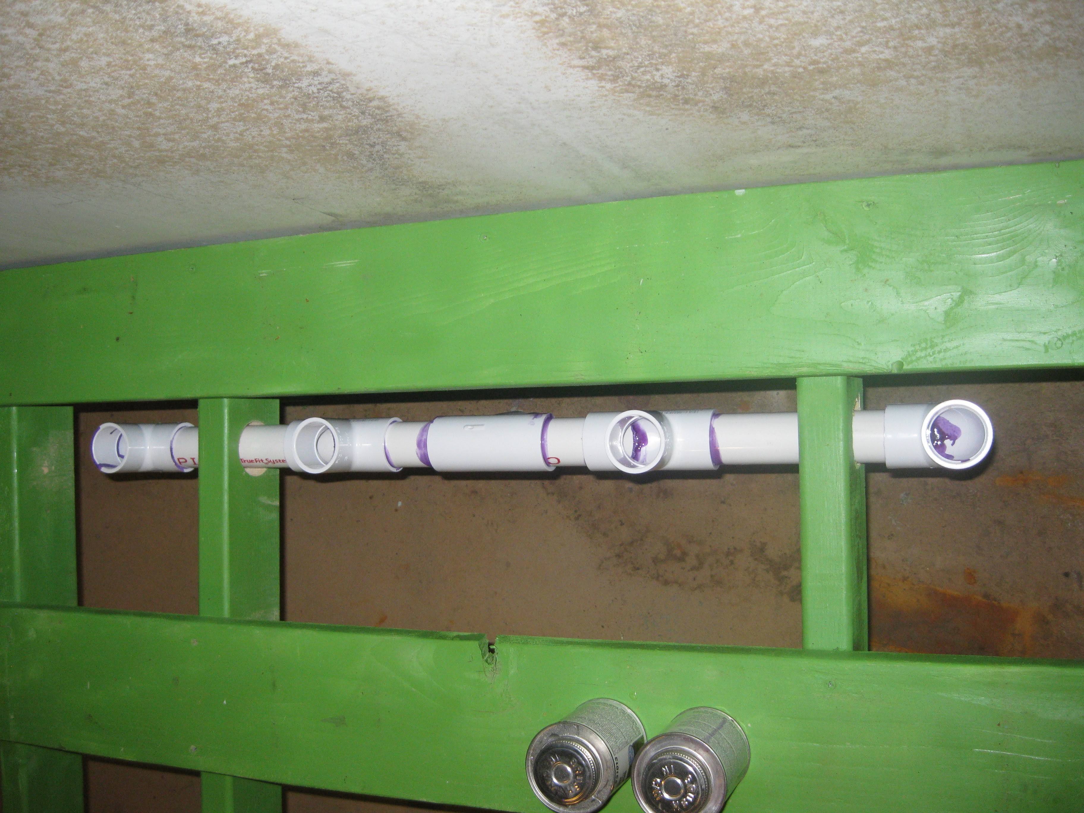
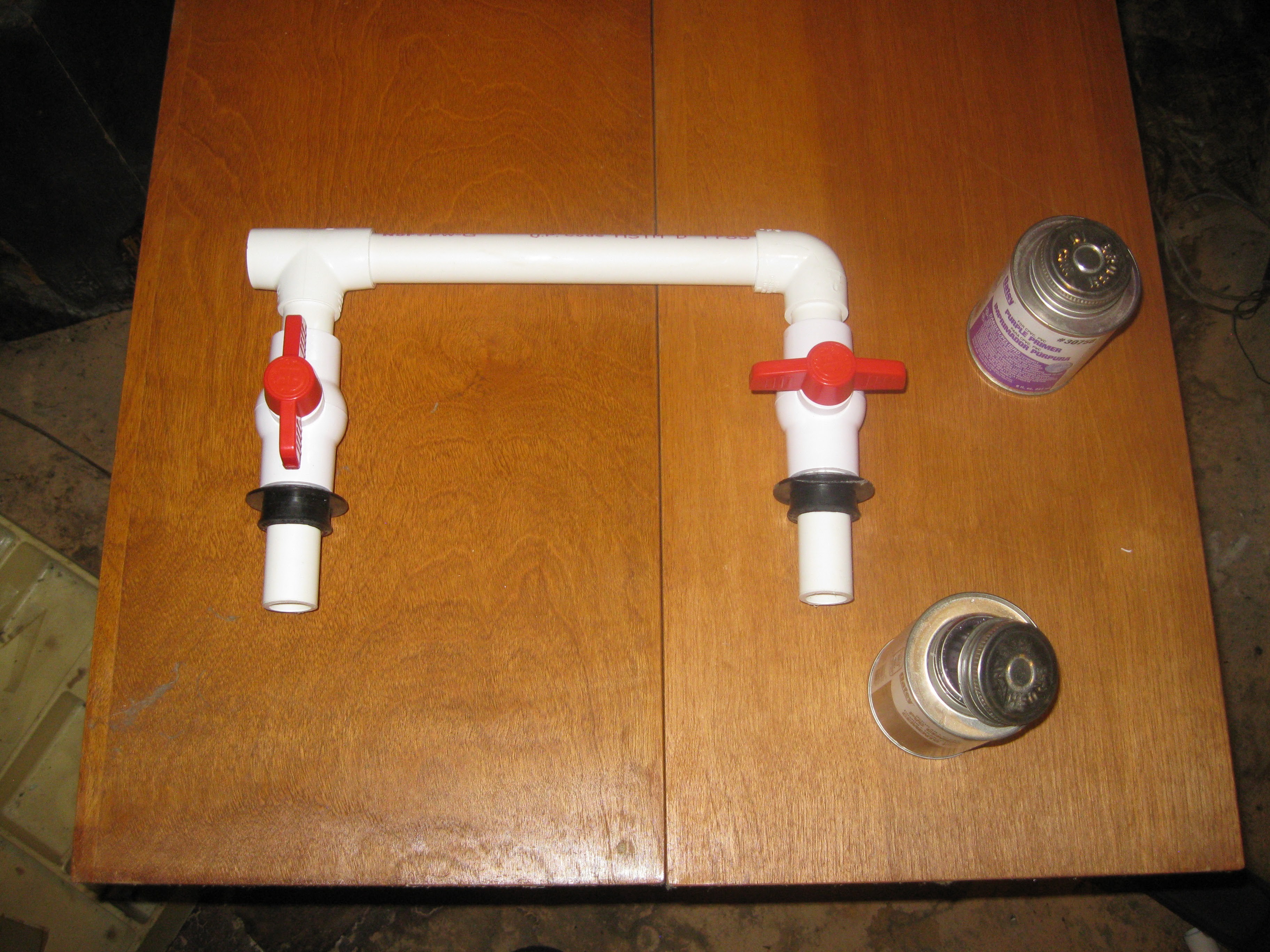
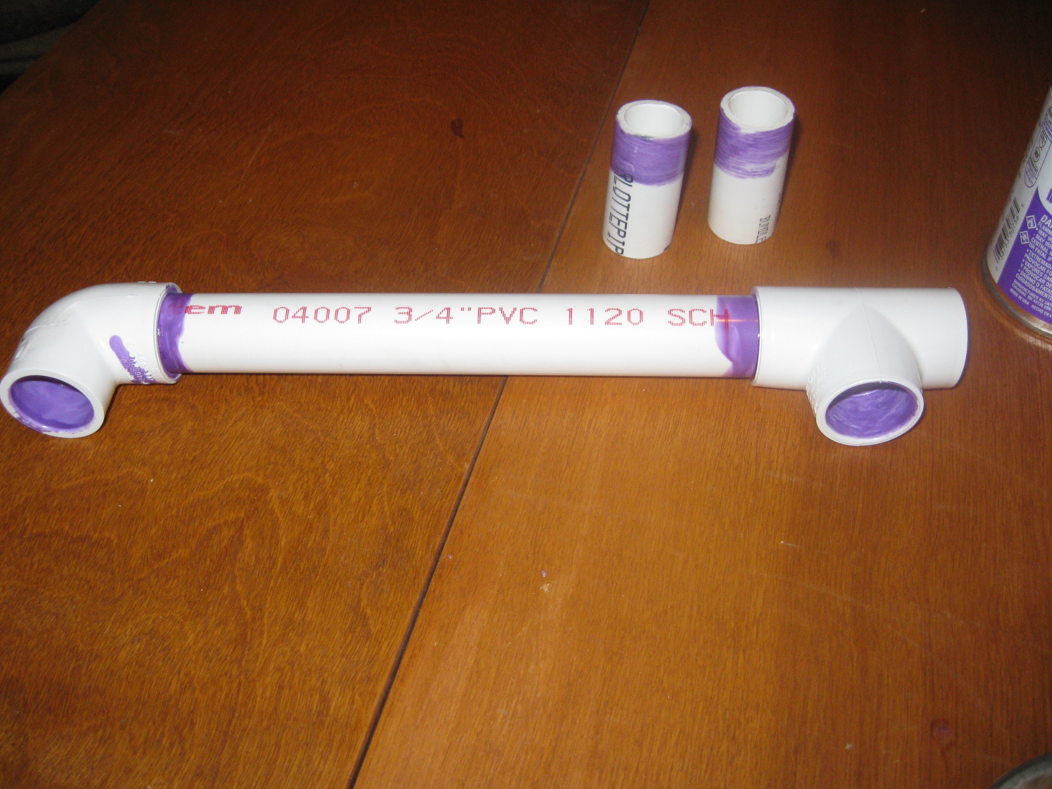
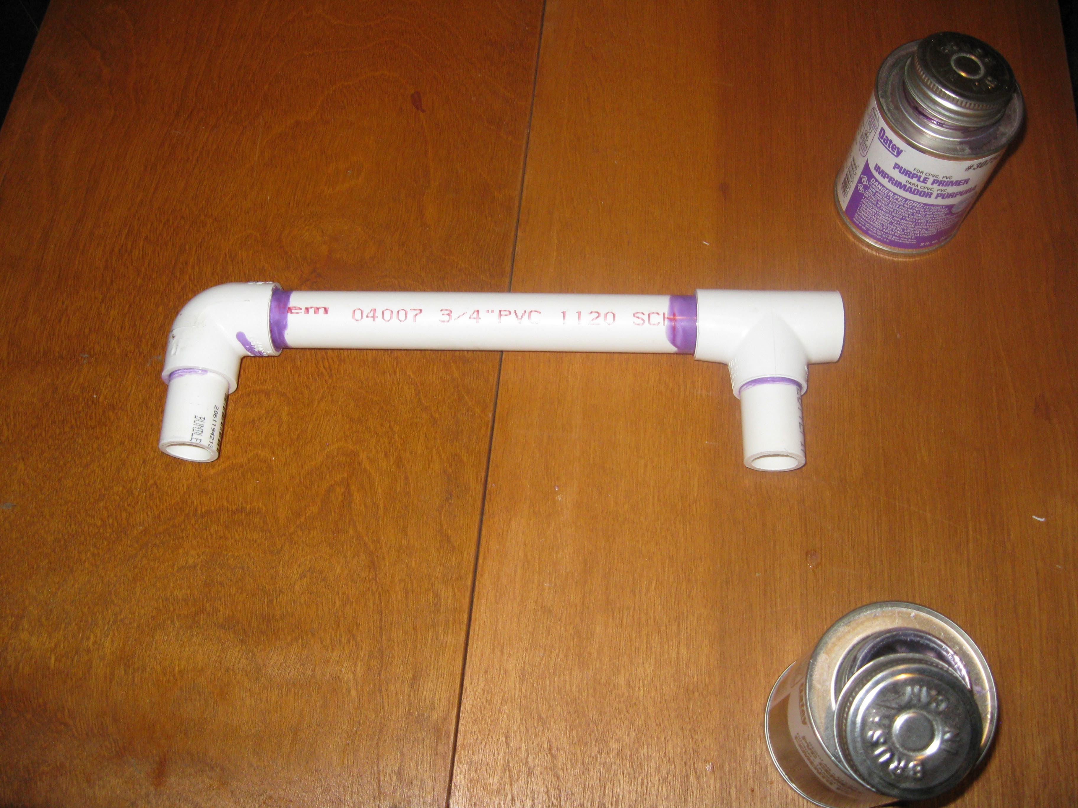
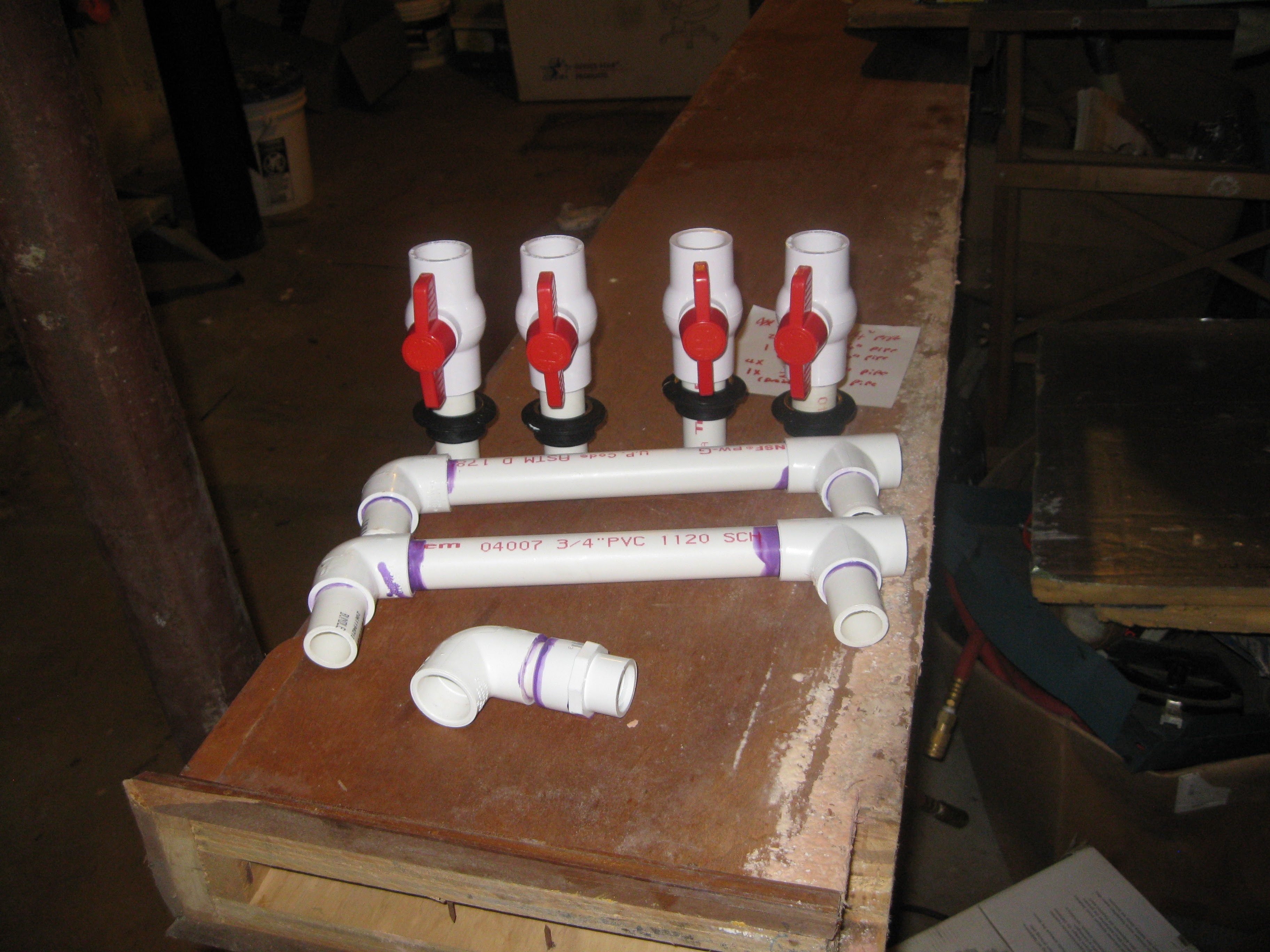
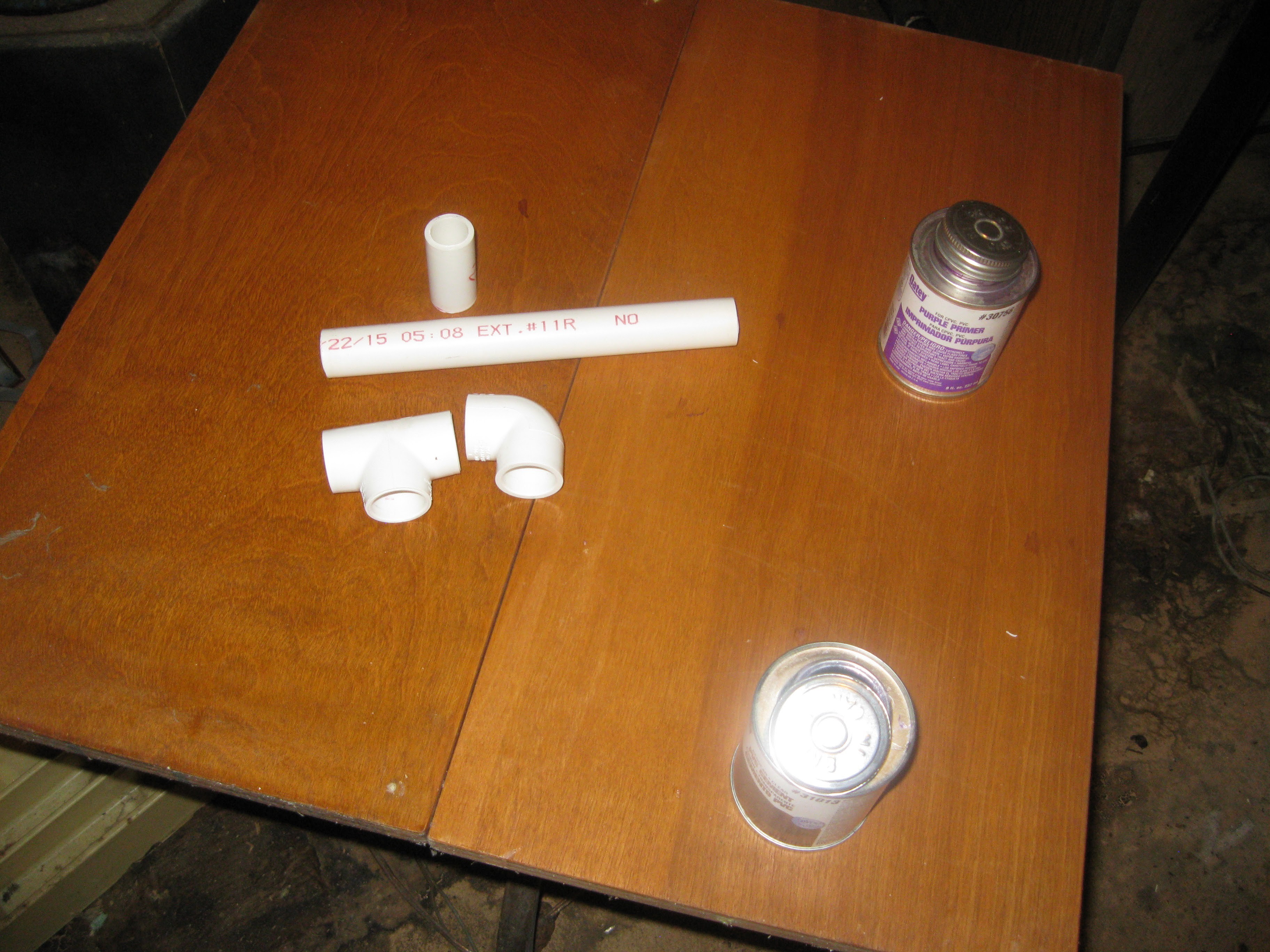
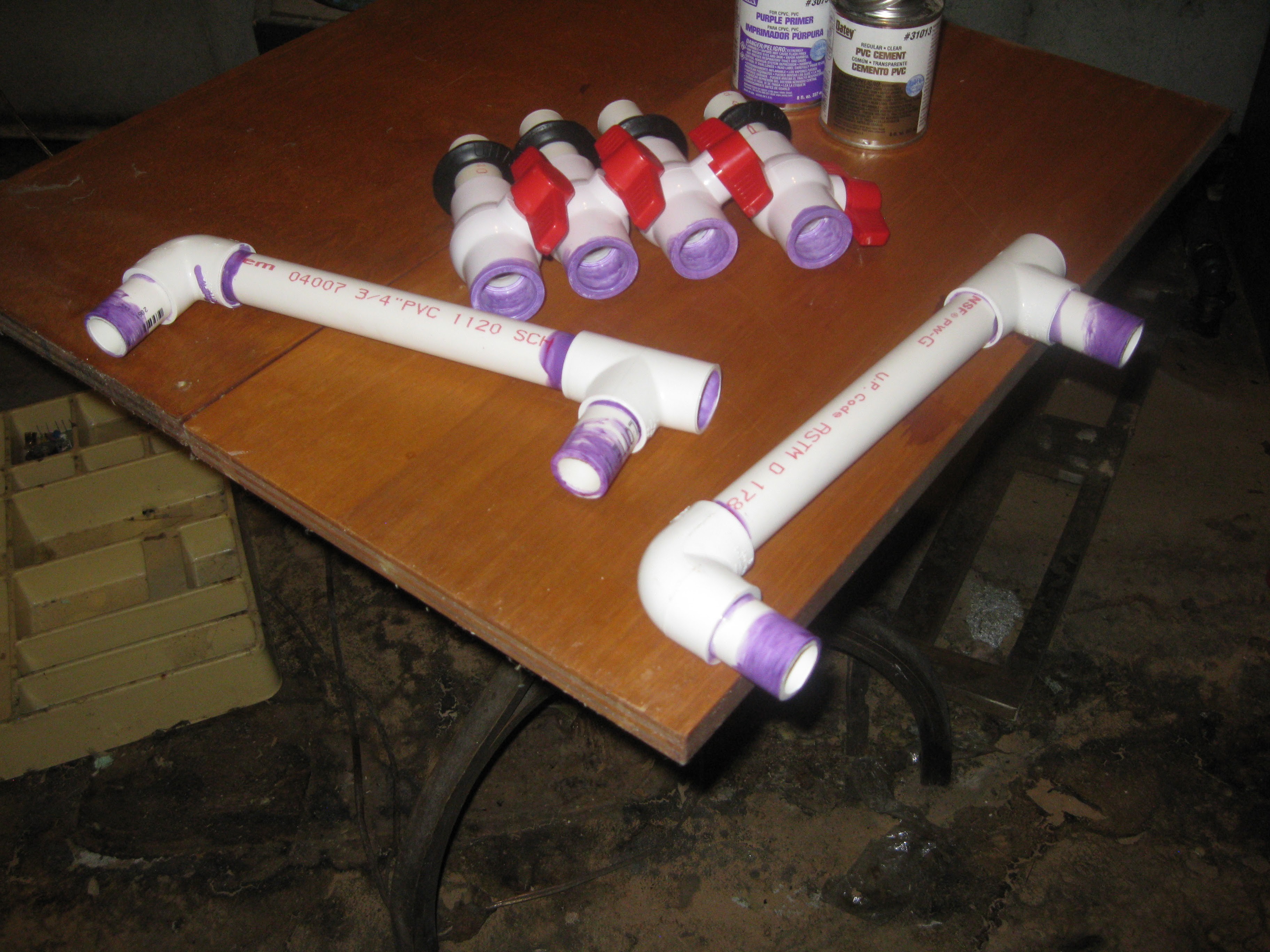
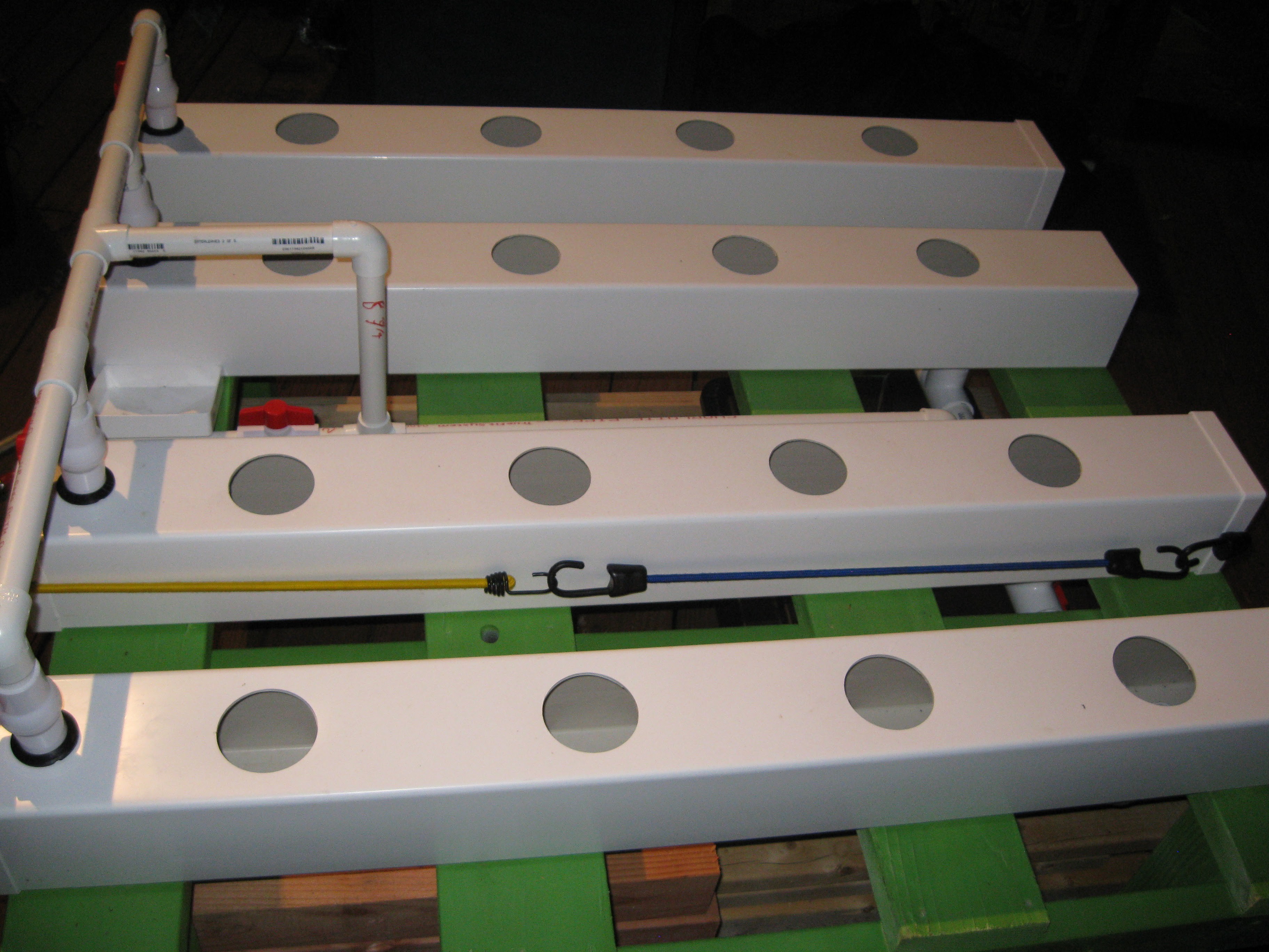
Most of the work in this log pertains to water circulation and management within the NFT grow system. As mentioned before and pictured the NFT grow system is constructed from PVC fneceposts and PVC pipe. The fence posts hold the netted pots where the plants grow, the PVC pipe is used for piping the water in and out. For this system I build an input manifold from 3/4 inch PVC pipe and PVC ball valves. The purpose of the ball valves is to so the water level inside the fenceposts can be adjusted, when the plants are first starting out the water level has to be high, when their roots grow big enough the water level can be lowered. Eventually I intend to motorize these valves and add sensors to enable closed loop water level tuning. The next piece I worked on was the drainage manifold, it consists of 1 1/4 pipe and a few 1 1/4 inch fittings. The drain manifold is made from larger sized PVC so that the water drains fast enough relative to the circulation pump. In the picture below I show how the drain manifold will go together:
Pipes, fittings, valves, etc
![]()
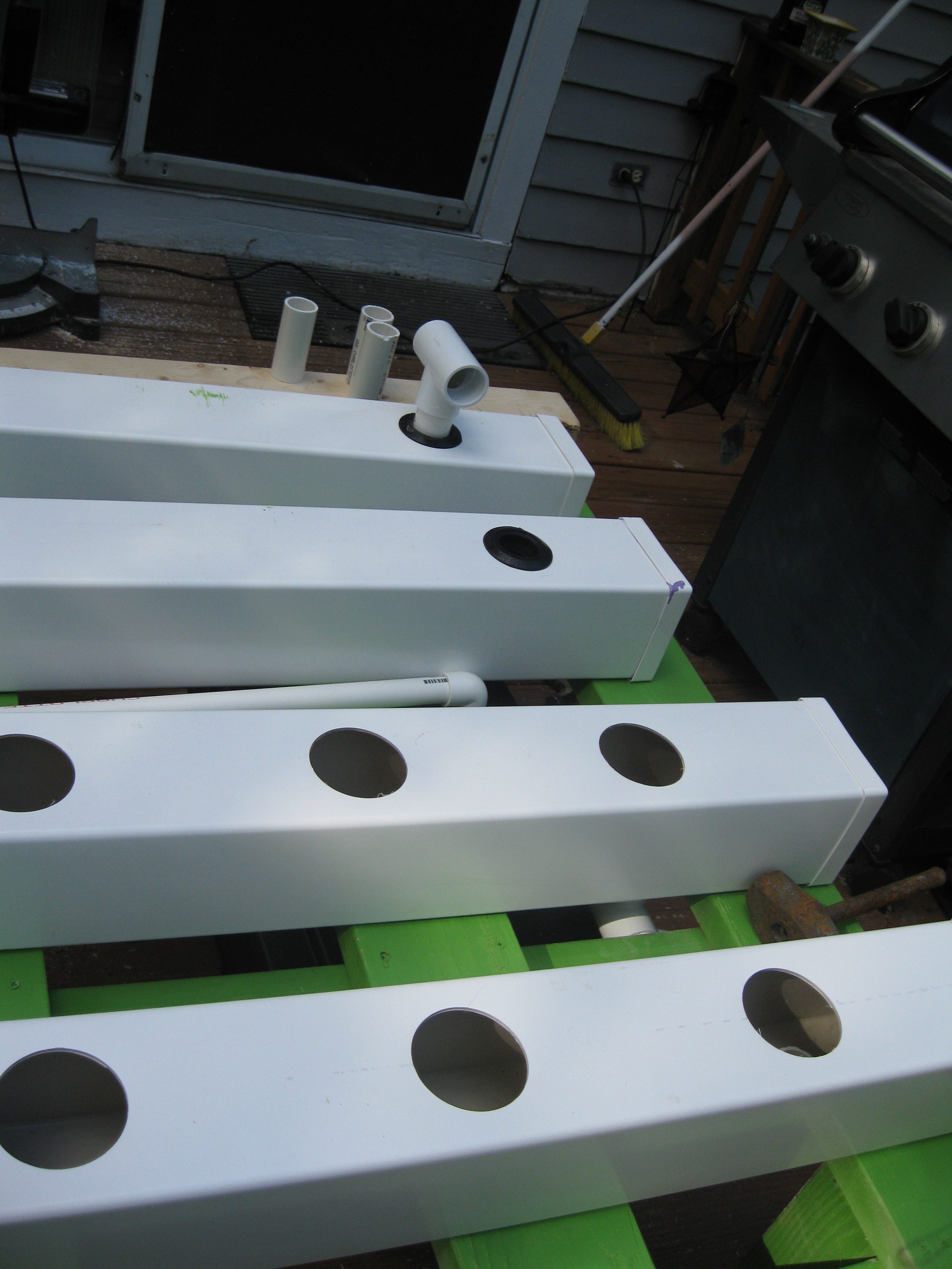
As for attatching the manifolds to the fenceposts I originally was planing on drilling holes in the endcaps and using PVC glue and epoxy to hack it all together. I decieded that would be a rather terrible way to put it together so I did some research on what other folks are doing with similar builds and someone recommended uniseal gaskets. They work really well and they are very simple to install, basically you buy a seal based on the size of pipe and they have a hole-saw chart explaining what size hole is required for the seal, just drill the hole pop in the seal and push in the pipe, water proof and you can take it apart for cleaning. Here is where I got them BTW http://www.aussieglobe.com/uniseal1.htm
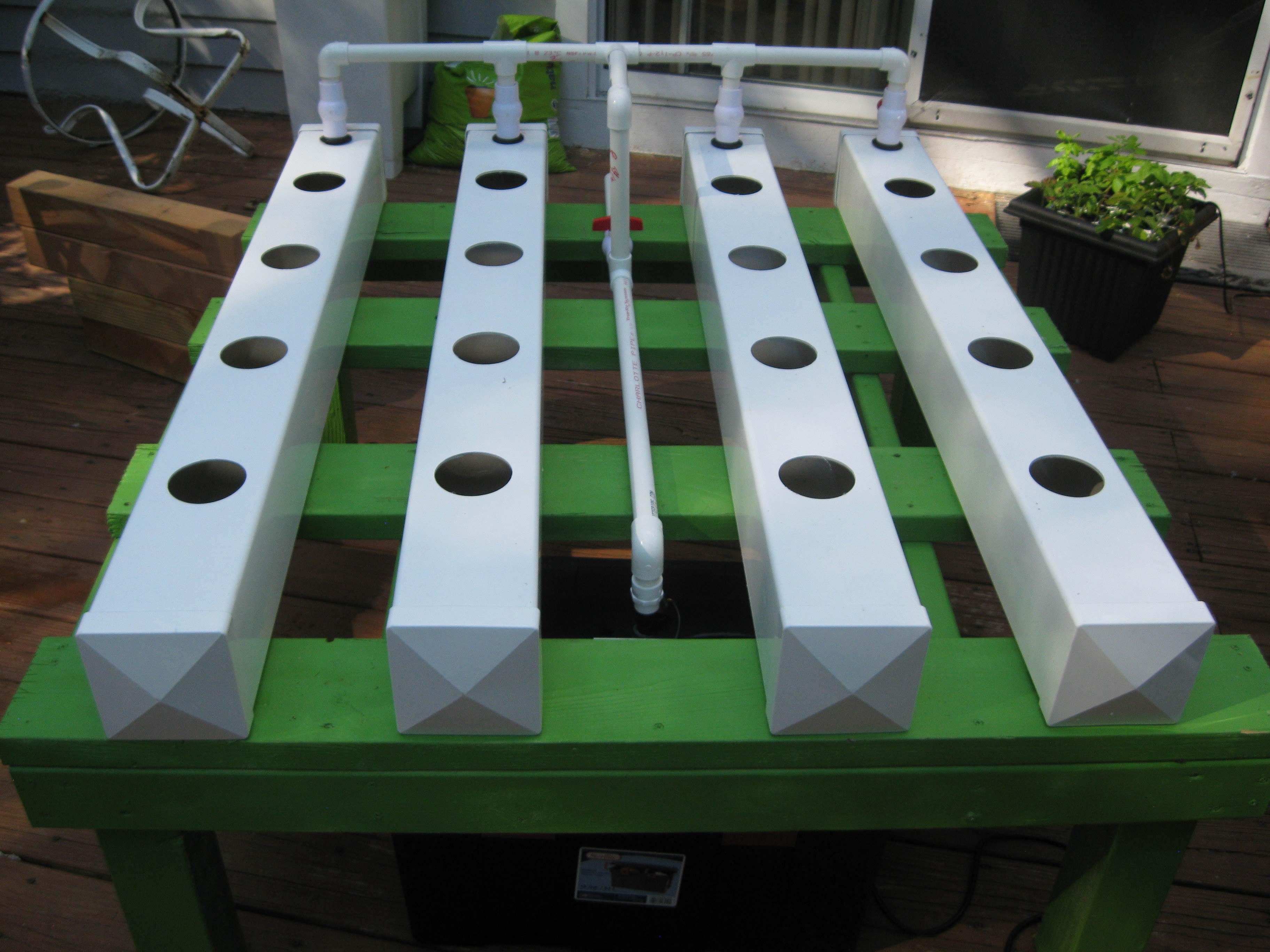
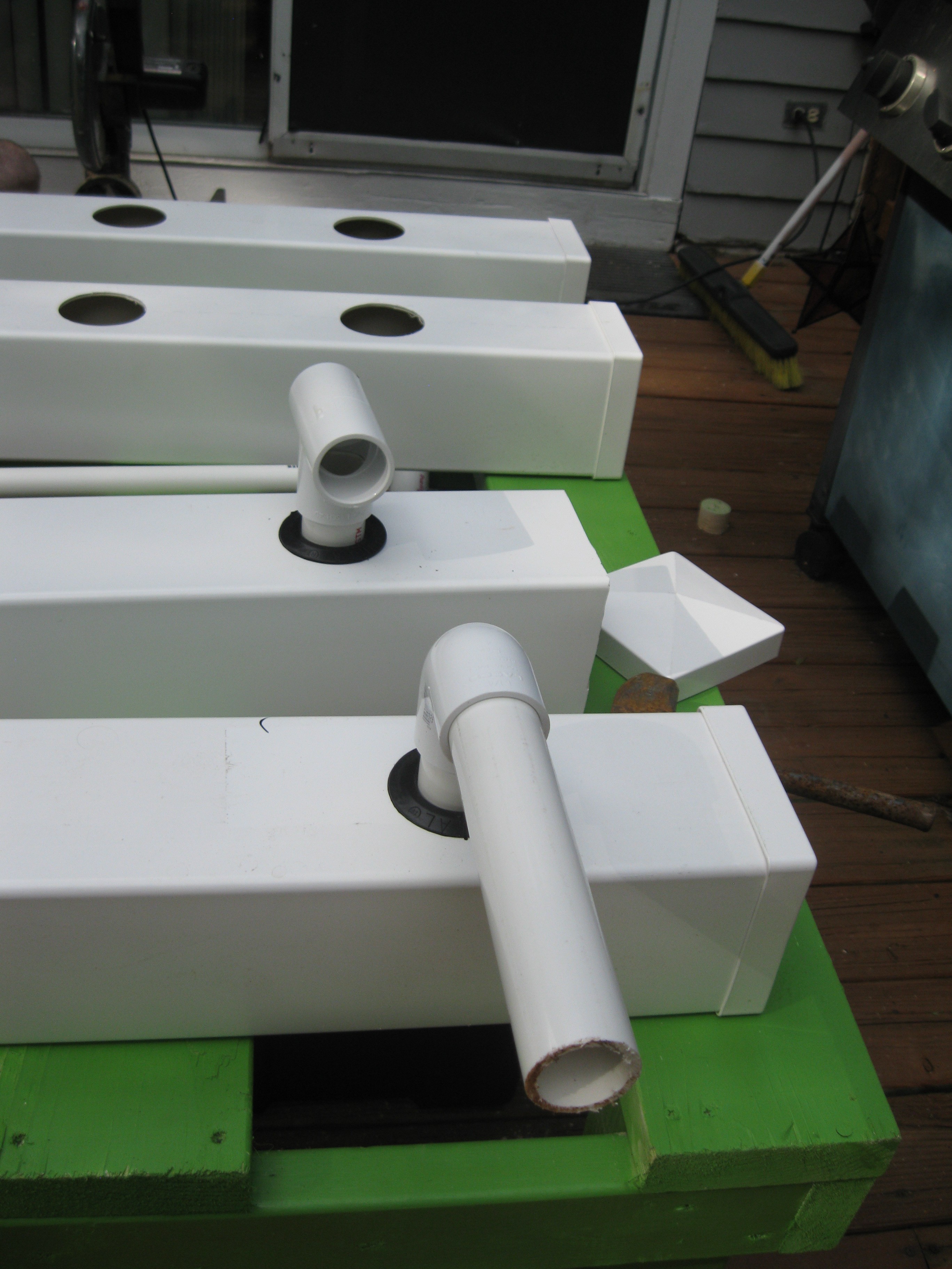
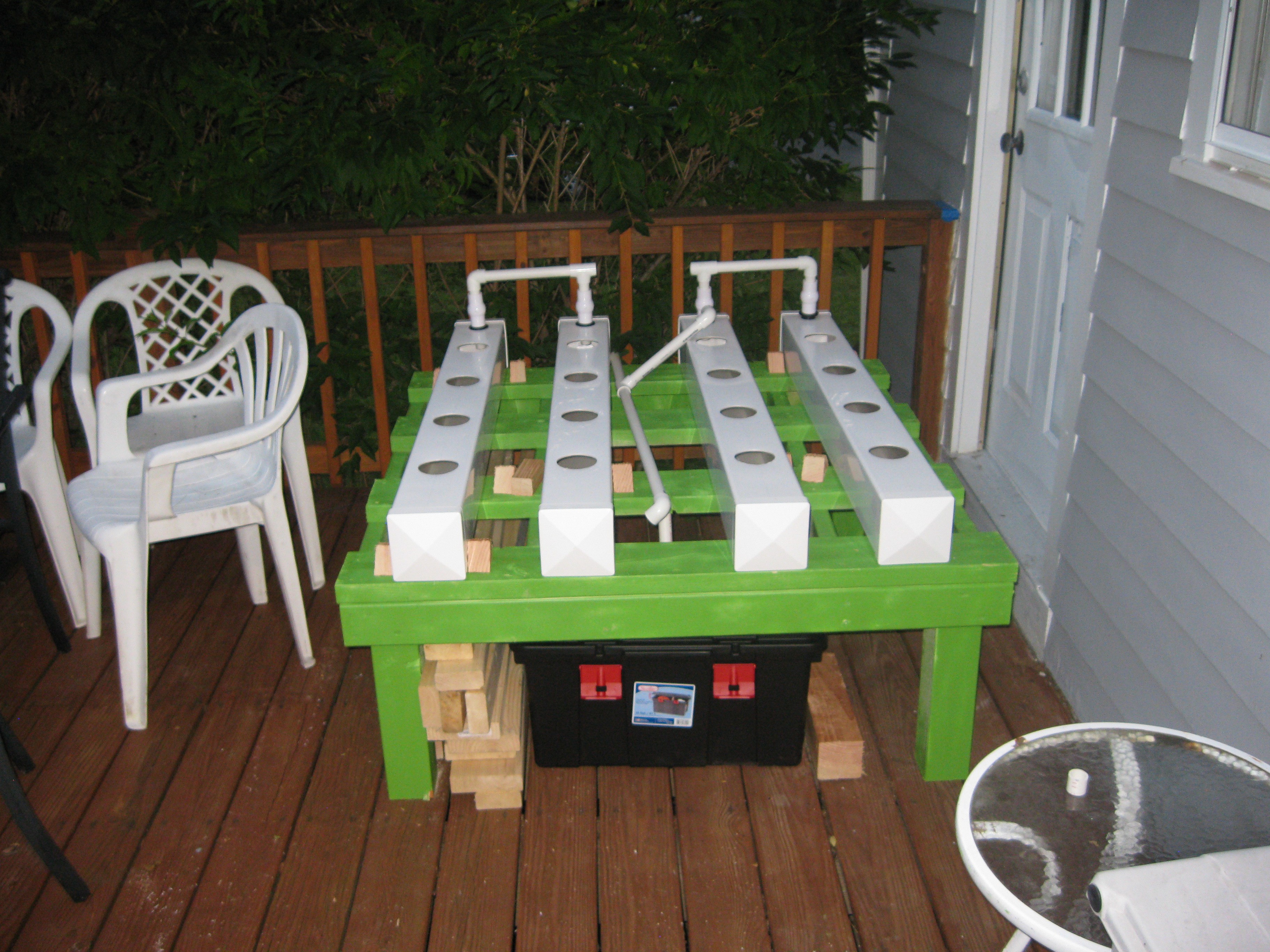
The input manifold pictured not yet finished, next pipe needs to be cut to join the two sides with a t fitting in the middle that connects to the circulation pump in the reservoir. Also in the picture the two halves are different sized, I was still deciding on the exact spacing I wanted. I should also note that I primed and painted the wood frame to that nice planty looking green color, I think it turned out great and gives the rig a nice look, the plan is to build another rig but paint it a different color. Its really just for fun.![]()
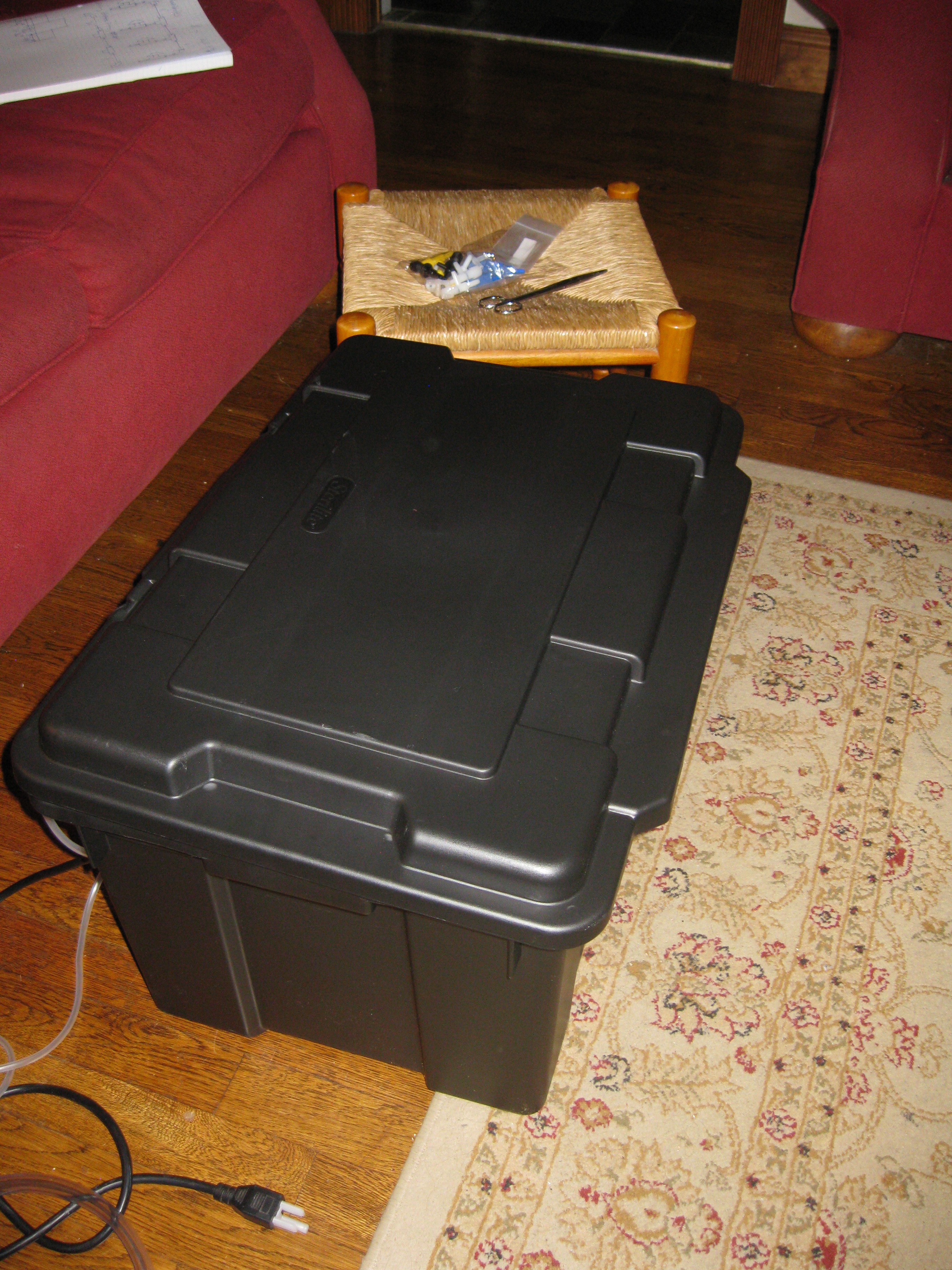
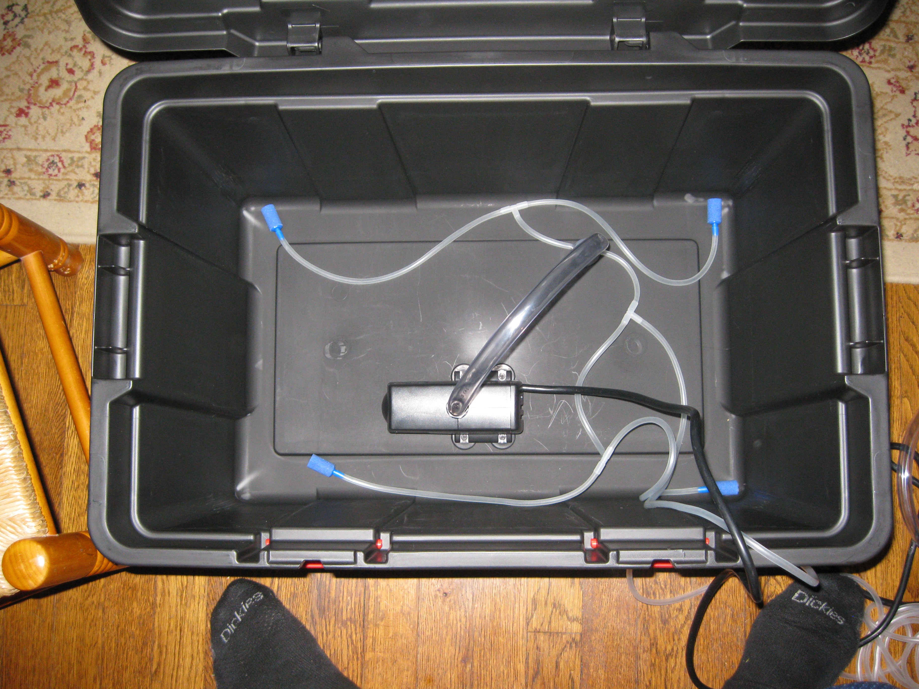
In addtion to the manifolds I finally found a reservoir for the system. I was planning on a 55 gallon water barrel originally but that would be too much water and require a bigger more expensive pump, I also decided to build the green two by four stand shorter in case plants get way too tall. The next idea for a reservoir was a storage container, at first I was going to go with a 10 gallon container but ultimately decided to get a 16 Gallon container because the dimensions allowed for a better fit underneath the grow system itself. Inside the reservoir is s submersible pump used for circulating the water through the NFT system, connected directly to the input manifold. Also in the reservoir are aquarium airstones connected to an aquarium air pump , this serves to aerate the water/nutrient-solution and agitate it to prevent stagnation/algea growth.
Submersible Pump, airstones, tubing, fittings, and leftover air valves.
![]()
16 Gallon storage container, AKA the reservoir!
![]()
Rervoir internal setup, 185GPH submersible pump and airstone setup.
![]()
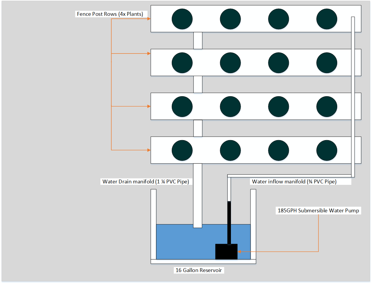
How all this works:
The diagram above should explain the general idea behind everything discussed in this log update. The pump sits in the reservoir and pumps water into the fenceposts via the input manifold, the water drains after flowing from the fenceposts into the drain manifold and back into the reservoir. Stay tuned for more!![]()
-
Custom Grow Lights !
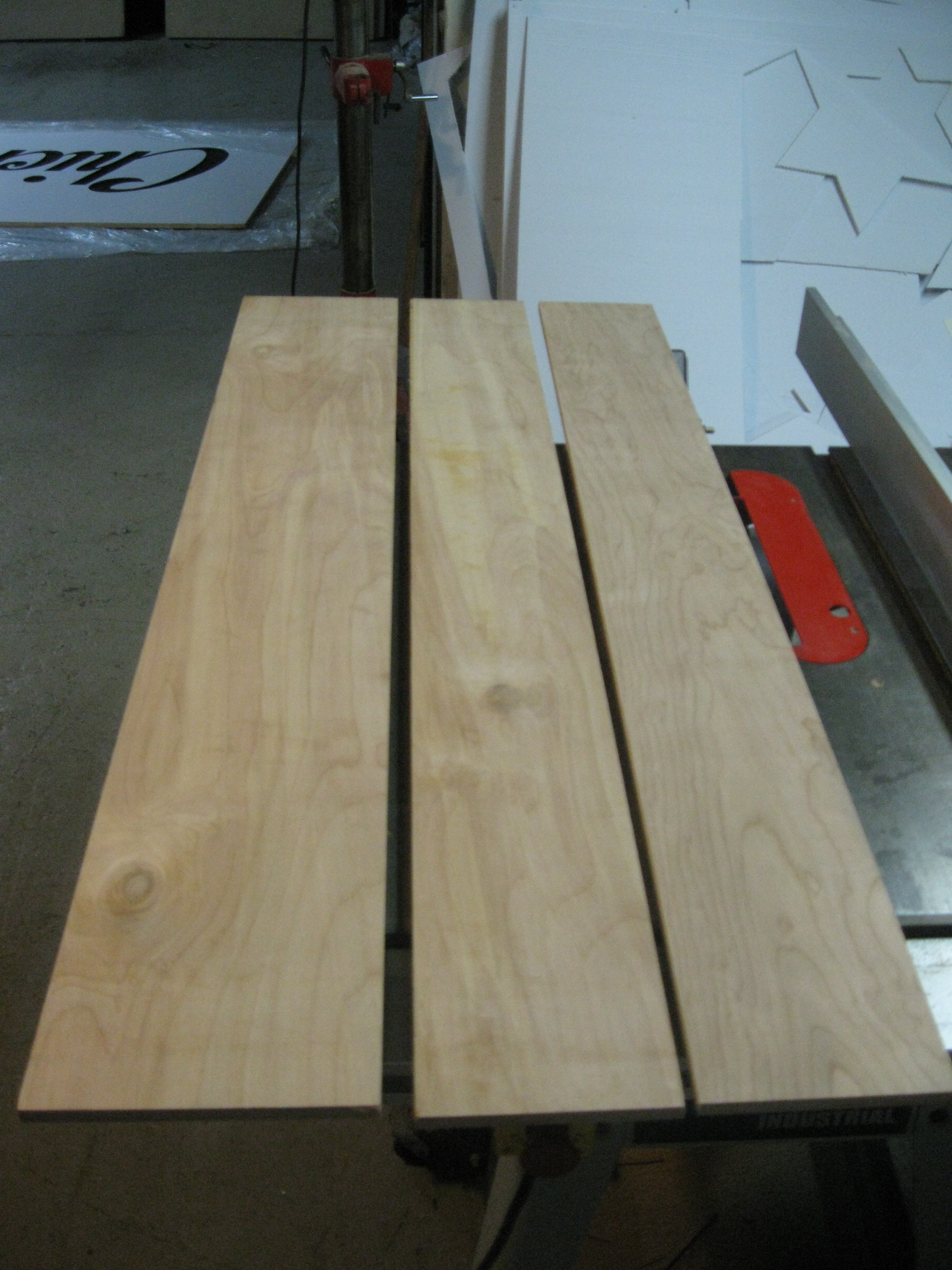
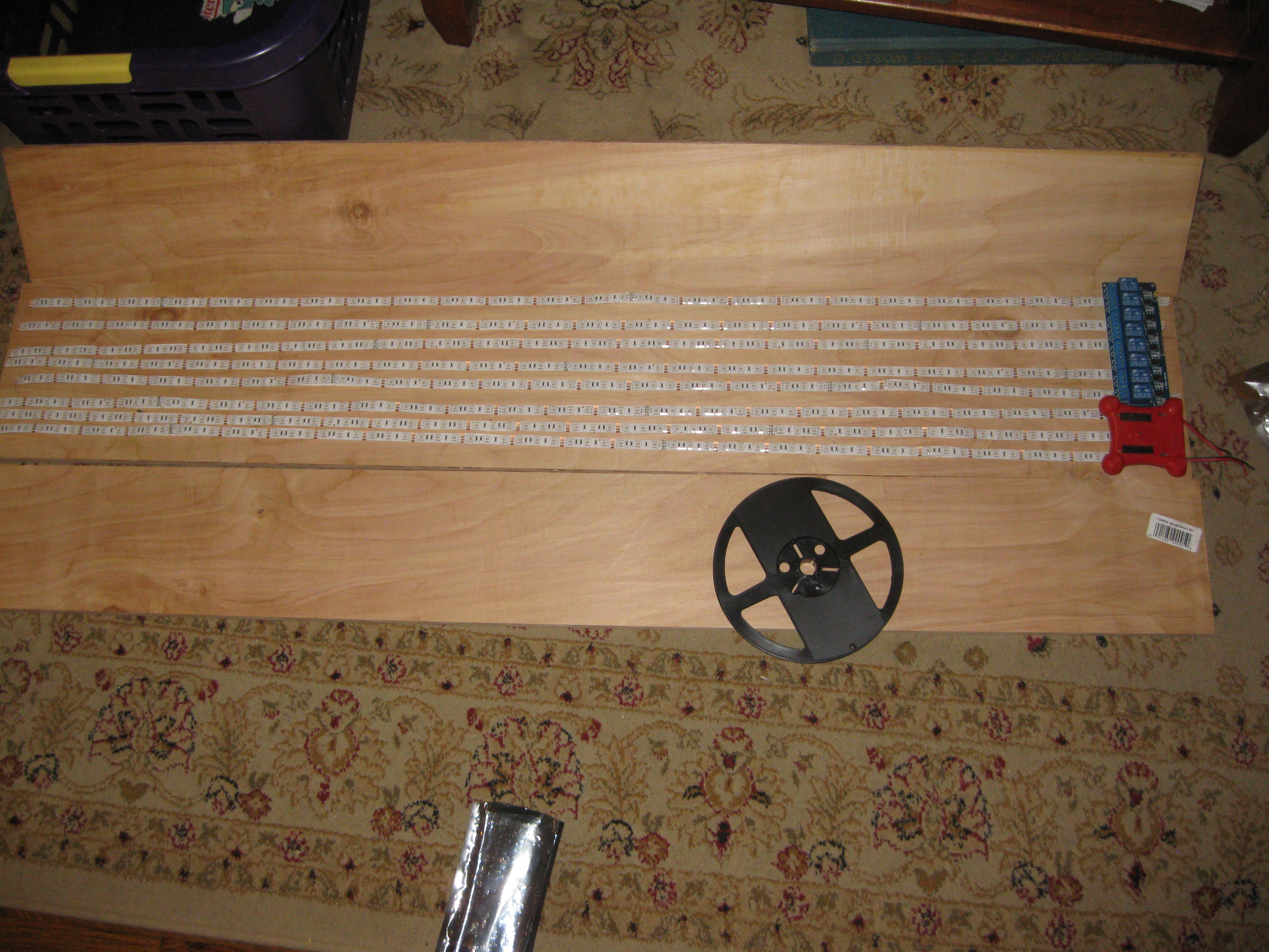
08/11/2015 at 06:03 • 0 commentsSo last week after a short vacation I got some work in on the project. The electronics is on hold while I develop the embedded software a bit further and order some more swtitching regs. In the mean time I have been working on other aspects of the project. I am buuilding custom LED grow lights that will be powered of cheap switching PSUs, the standard LED power supply you find on ebay. The LEDs are 5050 variety mounted on strip, they are two red wavelengths and one blue wavelength (forgot at the time of posting), between this combination the plants should get all they need. I also got some 5050 purple LEDs too to mix in for more wavelength variety. The lights are a simple plywood design, three cental boards cut with 60 degree bevels glued together to form a half hexagon shape. Ends will be made from ply wood ans well and the whole assembly will be glued and screwed together. The inside will be plated in tin foil mounted using spray mount glue. The electronics for driving/switching the strips wil be mounted on the outside one end of the light. So far I started building one light, I havent decided 100% on how they are gonna work/be controlled, the tentative idea is using a DyIO and the 8 channel relay board you can get off ebay to individually switch strips on an off , allowing for changing light coor temp configurations or cutting power down to save on energy costs. I might just wire them all in parallel and just power them straight, not sure yet. Anyways I took some pictures of what I'm working with:
Boards Cut for custom grow light, half inch think birch plywood.
![]()
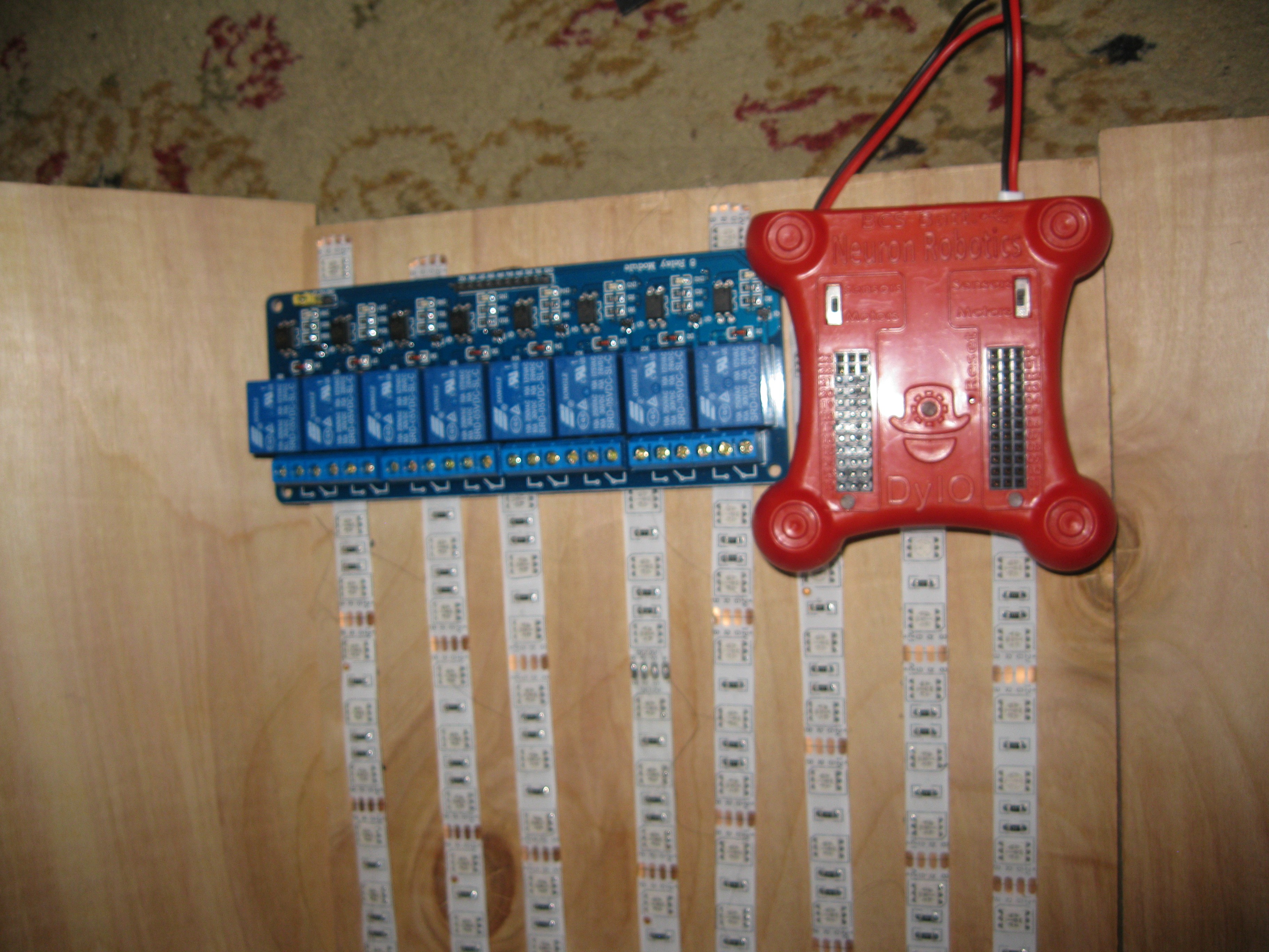
laying out the LEDs on the board with the relay board and DyIO module
![]()
Up close shot of controller electronics
![]()
Stay tuned for more!!!
-
Hardware Build Update
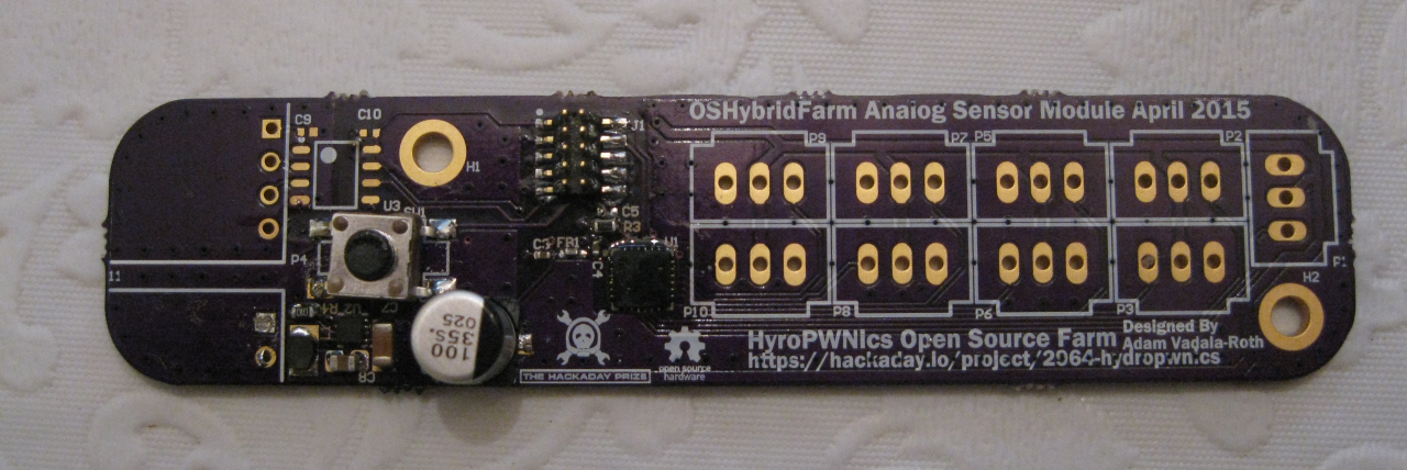
07/27/2015 at 20:56 • 0 commentsFriday of last week I started assembling the hardware. Most of my time was spent organizing components and tracking down all the tools and missing parts at the hackerspace. I didn't get as much don the first day but I didn't expect to, hopefully this week the build will pick up pace and more will get done per day. Anyways the first board I got started with was the analog sensor module PCB. Following my PCB population protocol I described int he last update I started by populating the power supply of the PCB first. In the case of the analog sensor module the power supply consisted of a TPS62162DSG DCDC switching regulator circuit with a fixed output of 3.3v. First I assembled the regulator then I cleaned up the board with isopropyl alcohol and a toothbrush just to get rid of flux and solder balls that could cause shorts. Before moving on with any more assembly I tested the power supply circuit. When testing a voltage regulator its best to limit the current on your benchtop powersupply to mitigate the severity of component failures if there is a short or mistake in the design. In my case I limited the PSU to 100mA at 12V , when I tested the board the regulator powered on successfully and outputted a steady 3.3v volts!! The regulator working on this board is a good sign for the rest since they are using the same circuit and same PCB layout. Given that the power supply worked, I populated the microcontroller part of the PCB, however I held off on testing it because I still am figuring out the programming routine for the Kinetis chips from the Kinetis IDE. Anyways here is a picture of the first PCB so far:
So yeah more to come on populating PCBs in the coming days, also i hope to have a guide up on the wikis on how to setup toolchains for the MCUs and SoC hardware being used on the HydroPWNics project. Stay tuned!!!!!![]()
HydroPWNics
An open source hydroponic garden control, monitoring, and grow system with cloud database and dashboard.