charliex
-
More GUI updates
12/03/2014 at 06:32 • 0 commentsChanged the grid to use combo boxes instead of numbers the patterns, that way they can have descriptive names for the patterns and not have to remember 201 means fade to red. Started to color match the boxes as well , though i havent dont all the names yet, for some color switches that aren't patterns i might just go forgo the text and set the combbox to the colour it's changing too.
next is to add a display that shows the states of the lights.
-
updates
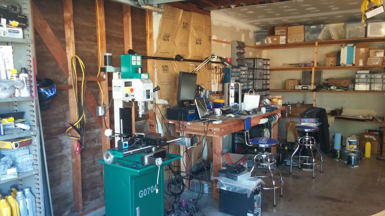
12/01/2014 at 19:56 • 6 commentsWell lights up day was meant to be Sunday, but we decided to start finishing the drywall on the garage which is my home shop, so that took three days of the holiday, krs had to do her sisters bridal shower event as well, so all in all a very busy thanksgiving. but i got some time to work on them.
went from this
![]()
to this
![]()
We just finished as the rain started, so had to get all of gear back in at like 10PM, in the rain... so yeah fun time, and didn't get a chance to clean and seal the floor, or at least prime the drywall Oh well, its getting there. I also left a bunch of wood outside, so thats gonna take 6-12 months to dry out.
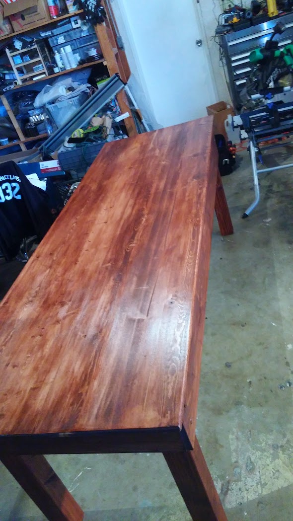
Also finished (mostly) the table for krs, that had to be done before we started the drywalling because of the dust.
![]()
New Things.
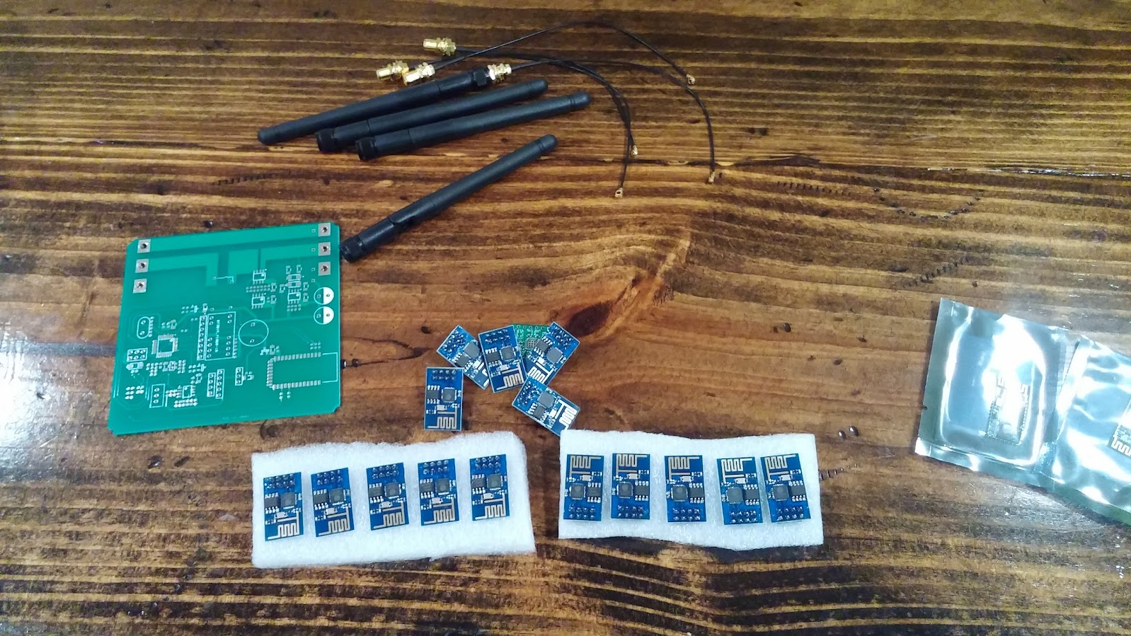
Ordered another 20 of the ESP8266's from alibaba, they arrived and i programmed them all for my AP and 460800 baud rate , and so far so good, i built a small usb uart to 8 pin header for the programming and just used that to rinse/repeat. Though this prolific adapter doesn't work as well and you have to reconnect every time, and every 10-20 reconnects you lose the port. Luckily these ones came with the same firmware I've used.
I also got 4 of the external antenna versions to test, have no hooked them up.
![]()
The PCB's arrived from itead and kris put a couple together, they worked off the bat but i hadn't noticed i'd used the debug lines for one of the GPIO's, it didn't matter since i wasn't going to be debugging these anyway, flashed the firmware in and i dropped 20 psocs on the boards and left the rest for her, i of course forgot to order the parts on reels/strips in time so we could use our pick and place. which would have breezed through this. ah well. i did find a full reel of 10K 0805 resistors in the first box i looked in, considering (a) how many we have and (b) how much of the house was a mess since it was moved out the garage into the house during drywalling, i'm amazed how lucky i was to find them when needed.
The top right board is one of the "free 2 boards" from itead, it looks like some sort of bluetooth/wifi power control switch the other one was a reprap motor controller, and the first board i've gotten from itead in that jumble that i could figure out what project it was for.
The esp8266's cost me about $3.20 each.
The new node designs have the programming pins broken out.. so super easy to program, all you do is solder the chip to the board and use the cypress programmer, no other components needed for flashing, which was great for batching. I'm a tad worried the little smd switch has the make contacts on the wrong side of the pcb schematic, but its not really needed since it was a shortcut for bootloader mode anyway.
The control software is now able to control up to 255 nodes, and for pretty much any song length, i've got it set to 250ms steps at the moment, i'm adding in the various patterns and figuring out how i want it to work. I've been thinking about how to split up the rows of the table to match the song being played, maybe with a bpm/tempo match, but a lot of music is at things like 148BPM which doesn't easily match up to a nice uniform number. 60,000/ 148 = 405.40540540540540540540540540541 etc but we'll see as i go along, variable control over the range of the song would be great, so instead of just doing row*n, you give a list of times to fire the pattern, and no dead data, which might make a lot more sense, I'm mulling it over. Then insert/delete rows as you go along with new times..
Currently I'm just putting in numbers, so 1-15 are various preset patterns, 100-164 means switch to color 0-64 immediately, 200-264 means fade to colour 0-64 etc, there's a preset CLUT for those too. 0 means no change.
Had to stop about 10:20PM last night, since were just worn out. It's one of those times where you're too tired even to take pictures and document, so i'm at least adding what i recall here. krs managed to get about 70% of the itead boards completed.
Today i'm thinking about changing the numeric values in the grid to a ComboBox with a text+color representation of what will happen at that time spot, then adding a display control that shows what each strip is set too, that'll be interesting since they're 150 leds long and up to 256. i might just make it a bitmap, we'll see.
I also started a rev of the board that runs the PSOC at 3.3V this should need less parts since instead of level shifting everything between the ESP8266 and the psoc, its just the LED control signal that needs to be level shifted to 5V. I really should have sent in a build of that too, since its a few less components to build, well really i should have had the parts ordered in time and used the pick and place! But time sneaks up on you, I can't believe it's already December, it was just summer.
Now that this rev i know works i'll post up the eagle files. Though i also flipped the 8266 so it points away from the board, and moved that GPIO.
The 3rd gen board will be 3.3V primarily.
Maybe tonight the rest will get finished and we can start to waterproof and install them this week, definitely by the end of the week..
cheers
-
external antenna + USR-WIFI232-T
11/13/2014 at 22:13 • 0 comments
bought from here http://www.ebay.com/usr/goldy0903 arrived in a few days. not sure if its the best deal around,![]()
data sheet http://en.usr.cn/download/USR-WIFI232-T.pdf
hopefully i'll get time to mess with it at the weekend.
-
Built one of the prototype boards, don't know if it works :)
11/04/2014 at 17:59 • 0 commentsThe Wife put together one of the proto boards, but i thought/or assumed that the psoc4 would have a uart bootloader on it already, didn't seem like it, and yeah i didn't break out the programming ports since i was trying to keep it single sided and small.
So just have to lift the chip program it with the bootloader or find out why the bootloader that might be on there isn't working,
She wasn't so happy after i realised that !
Another point to add to check list, make sure micro has bootloader loaded.
I've also been thinking about running the PSOC at 3.3V and just boosting the signal to the LED strip to 5V, that'll cut down on the number of components on the board by a bit. Off the top of my head the PSOC4 should still clock at max at lower voltages, but i'll check before I do the change.
Also I might add an ADC for a mic or something. I'm trying to keep it as simple as possible but i can see the usefulness of an ADC for this setup.
I'v got a stack of test clips that go over chips, but of course i never have the one i need and they're crazy expensive , I typically use them for ECU work so i can justify the costs there, and occasionally you'll find them on sale at places, i bought a bunch from a place in Vegas for $5 each, but none of them are right size, of course. You can clip on the little test leads or solder on , but with the CNC milled boards at this pitch it is really easily to lift a pad or track. I'd rather delay and use the right kit than mess up a board the wife put together.
-
Writing the controlling sequence software
11/03/2014 at 23:39 • 0 commentsSo now that hardware/firmware side is at an alpha-ish level, it needs a front end to drive it and sequence to the music so on Sunday i put this together.
It's an MFC hosted app where each of the sub window is part of a base class, so you add them with callbacks and they can process the data in their own unique way , as well as communicate with each other.
If you've seen something similar on my you tube channel it is indeed a rework of my third gen ECU tuning software that never got finished, so i'm glad I found a new use for it as I've always liked the framework, a few of the controls are scratch built, a few are from codeproject, Chris Maunders GridCtrl is in there for instance.
It can handle multiple songs at once, and the sequencer is controlled from the grid, the rows are time, the columns are individual LED controllers, the number being the pattern, script or container.
Using Visual studio + MFC its really easy to throw together a complex UI very quickly indeed.
I've got some tidying up and tie together work to get it sequencing, but its mostly there. Still thinking about how i want to design the grid.
Chris's control is great and its very expandable so you can cut and paste from excel or google sheets if you want to edit and layout in there, there is no point re-inventing the wheel, but this grid has enhanced cut and paste, multi select etc, and you can edit it as it plays etc. with undo/redo levels and all that jazz.
cheers
-
Two strips , independent streaming test
11/02/2014 at 02:05 • 0 commentsPut two strips out front to see how it they'd stream together from an AP 30 metres away.
-
First range test.
11/01/2014 at 19:23 • 0 commentsNow Halloween is over, I get to do a range test on it. Setup a strip + controller at the other side of the house, and booted it up. It worked! about 30 metres though the house to the AP that's buried in the back.
I'd had a second demo board made up but it worked strangely, turned out i'd flipped Vin and Vout on the LD1117 so yeah oops there. No ill effects though, so i'd basically been running the ESP8266 at 5V on that board, i'm sure it wouldn't have lasted.
Next changes are adding reset control and the two GPIO's to the PSOC on the custom PCB and get it sent out for manufacturing.
So i just looked at my other board, which has been constantly running since i started this project. I swapped the Vin and Vout of it too.. So of course who knows who long the ESP8266 would last now or if damage has been done that will take a while to show up, shortened the life of it etc, but it has been running full on at 5V power for at least two weeks continuously.
-
updating the firmware of the ESP8266
11/01/2014 at 18:17 • 4 commentsThere is lots of info on this elsewhere, but this is partly for me to easily find when i forget :)
Grab the esp8266 firmware flasher and binary, i used v0.9.2.2 AT Firmware.bin from here
http://www.electrodragon.com/w/Wi07c
CH_PD HIGH
GPIO LOWuse a low numbered COM port , 6 or less, you can change this in the device manager if needed, in windows handling comports about COM10 is slightly different so a lot of software won't do it
power on the esp8266 with serial at 115kbps
Run the flash tool, load the binary change the COM port to match, leave the second number (offset) at 0x0000 )
Hit download, should see this, I've always gotten the last warning.
connecting ....
Erasing flash...
Writing at 0x00000000... (0 %)
Writing at 0x00000400... (0 %)
Writing at 0x00000800... (0 %)
....
Writing at 0x0007e800... (99 %)
Writing at 0x0007ec00... (99 %)
Leaving...
Failed to leave Flash mode
After flash the ESP8266 settings will likely reset to 9600n81, enjoy new baud rates etc!, remove power , remove GPIO low , and restart.
AT+GMR prints the firmware id
0018000902
Set the baud rate
AT+CIOBAUD?
AT+CIOBAUD=115200
AT+CIOBAUD=230400
AT+CIOBAUD=460800
AT+CIOBAUD=921600Listen on UDP port 20002
AT+CWMODE=3
AT+CIFSR
AT+CIPMUX=1
AT+CIPSERVER=1,20002
AT+CIPSTO=9000
AT+CIPMUX=0Some other notes, the cypress bootloader host has a couple of small bugs, if you remove board to switch into bootloader mode, it'll redo the com port list and reset to the first entry. if you have the comport open in another app, it'll null out all the settings and then back to 9600 after closing the other software using the com port
With teraterm (maybe others too ) i can remove the dev board from usb and plug it back and in and it'll keep the serial going, which is really useful and acts more like a traditional RS232 port. But it also means i forget to close teraterm and the bootloader issue above kicks in, be nice to have a cmd line bootloader going instead or just have the uart bootloader integrated into the Creator UI.
-
460800 baud
10/30/2014 at 05:06 • 0 commentswent up in baud again, no problem either, no delay after the socket send now.
added the Fire2012 from FastLED just to see see how it looks, needs a shorter strip of 30 or so to look good i think.
-
updated firmware, faster baud rate
10/29/2014 at 06:26 • 0 commentsChanged to the v0.9.2.2 AT Firmware.bin firmware, set the baud rate to 230400 and now i'm pushing out 150 leds at 10ms intervals. looking nice. I'll keep increasing the baud to see how far i can go.
firmware update is just CH_PD high, GPIO0 low and run the update tool via the UART, i have an echo mode on the PSOC so it can proxy the uart and update the firmware.
Cypress PSOC 4 + ESP8266 WS2812 RGB XMAS Lights
802.11 WIFI enabled RGB LED Strips, using the ESP8266 and $4 Psoc 4 dev board.