-
More modules
04/04/2015 at 11:40 • 0 commentsI bought a couple of esp-12 modules with breakout board from ebay recently.
These modules have the same pinout at the esp-07 but have PCB antenna instead of the chip antenna.
The breakout boards work, but they have a couple of problems:
- No pinouts for decoupling caps for the LDO
- They are wide! Which means that they will fit on a standard breadboard, but they cover all the holes.
-
Back to the original SDK
03/17/2015 at 08:17 • 0 commentsIt doesn't seem like there is much support/updates for the RTOS sdk, so I'm going to switch back to the original SDK.
There are a number of things I'd still like to explore:
- Using the RAM in the RTC to store data
- Using MQTT
- Using the ADC
- SPI slave mode (maybe)
I've also been making some mods to the makefiles to make them easier to use.
-
Working with FreeRTOS
12/17/2014 at 10:08 • 0 commentsI've been re-compiling my demo apps with the new FreeRTOS SDK. This is a lot easier to use for network access, if you are used to a BSD style socket interface (which I am).
So far, so good. One thing I've noticed is the lack of support for reading from the UART. I've written some code to handle the uart rx interrupt and read the received data. Seems to be working so far...
Updated code is in github https://github.com/mattcallow/esp8266-sdk
-
Temperature Measurements
12/11/2014 at 11:19 • 0 commentsI've updated the lua code to read the temperature from a 1-wire temp sensor using the code provided with the nodemcu firmware
Results are on the same thingspeak channel https://thingspeak.com/channels/17374
I'm quite impressed with the nodemcu firmware. It makes it very easy to write simple scripts like this. Still don't like the upload method though!
-
nodemcu firmware
12/10/2014 at 12:30 • 1 commentI did some testing with the nodemcu lua firmware.
https://github.com/nodemcu/nodemcu-firmware
This is a handy scripting language for quick tests. Not sure I'd like to write a lot of code using it though. For one thing, I don't know lua, and also the upload process is a bit painful (I used this tool https://github.com/4refr0nt/luatool)
Anyway, I hacked a script to run at startup and do the following:
- Connect to my wifi
- Wait for valid IP
- log the boot time to thingspeak
- Sleep for 5 minutes
Now I can measure the time required to re-connect to wifi and send an http message after a boot.
Results are here https://thingspeak.com/channels/17374
(it's about 5 or 6 seconds)
So, I can re-do my earlier calculations:
- Sleep current: 50uA
- Wake current: 100mA
- Wake interval: 5 minutes
- Wake time: 6 seconds
Each hour, the device would be awake 12 times for 6 seconds at a time, (72 seconds or 0.02 hours) and asleep for the remainder of the time (0.998 hours). So average current consumption in any given hour is (100*0.02) + (0.05*0.998) = 2.05mA
So the 890mAh battery would last about 434 hours, or 18 days. That's not great, but better than my original estimates.
One issue still to resolve is the inconsistent sleep current. This varies from about 50uA to over 1mA!
-
New SDK version released
12/09/2014 at 23:30 • 0 commentsI've just seen that espressif have released their SDK on github
http://bbs.espressif.com/viewtopic.php?f=7&t=67
Now with FreeRTOS integration!
This looks like a big step forward in terms of ease of use. The demo application included uses a standard socket interface to send/receive data
I'm going to install this and update my examples.
-
Deep Sleep
12/09/2014 at 05:50 • 2 commentsI've been testing the deep sleep mode on the ESP-03. I loaded the frankenstein firmware from here https://github.com/nekromant/esp8266-frankenstein onto the module to test the deep sleep mode.
Note, you need to tie gpio15 to GND in order to boot any firmware on this module as shown in this table
GPIO15 GPIO0 GPIO2 Mode Description L L H UART Download code from UART L H H Flash Boot from SPI Flash H x x SDIO Boot from SD-card On the ESP-01 modules, GPIO15 must be tied to GND on the board. But on this module because the pin is broken out, you need to make sure that it's grounded at boot.
So, with the firmware running, I connect GPIO16 and RESET together and send the module into a deep sleep...
 === Press enter to activate this console ===
��rll��|�l�|�l�b|����r�b�b��nn�lnn���bplblrlp�n��lbn�|��l���b��nn�l��l`�nn�lnr���n���lp�n�r�����bn�|�l��b��nn��l`�nnl�l`nr���nbl``�n��b�nl���nn��lp�n�r�����bn�|���b��nn�l�l`�nnl`nr���nb�l`r��nb�l`25901
(c) Andrew 'Necromant' Andrianov 2014
This is free software (where possible), published under the terms of GPLv2
frankenstein > deepsleep 10000000
Frankenstein ESP8266 Firmware
Powered by Antares 0.2-rc1, Insane Mushroom
While the module is awake, current draw is round 70mA. In deep sleep this drops to 600uA which rather high (stated deep sleep current is <10uA) I try it again, and this time the current drops to 45uA, which is a lot better.
What I'd like to do, is create a battery powered sensor running of a old Nokia 890mAh 3.7v LiPo
Some quick calculations:
- Sleep current: 50uA
- Wake current: 100mA
- Wake interval: 5 minutes
- Wake time: 30 seconds
So each hour, the device would be awake 12 times an hour for 30 seconds at a time, (360 seconds or 0.1 hours) and asleep for the remainder of the time (0.9 hours). So average current consumption in any given hour is (100*0.1) + (0.05*0.9) = 10.045mA
So the 890mAh battery would only last 89 hours, or less than 4 days. That's not really good enough for a battery sensor. (Compare this to some other battery sensors that I've build using NRF24L01+ modules which get about 10 weeks life out of the same battery)
I'll do some experiments to validate my estimates (especially the awake time) to see if this can be improved.
-
New Modules
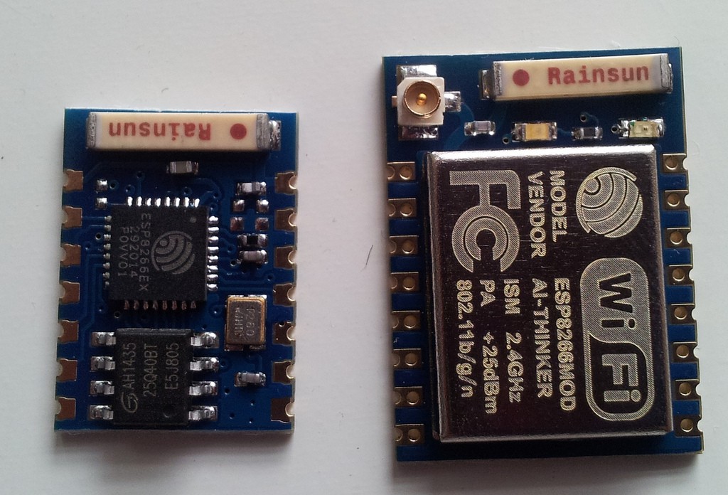
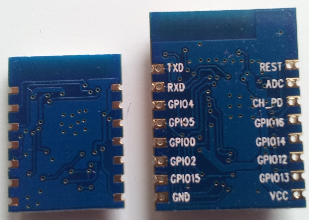
12/09/2014 at 03:03 • 0 commentsI got a couple of new module types recently and have started to experiment with them. On the left is the ESP-03, and on the right is the ESP-07. Both modules have 2mm pin spacing, so are not breadboard friendly.
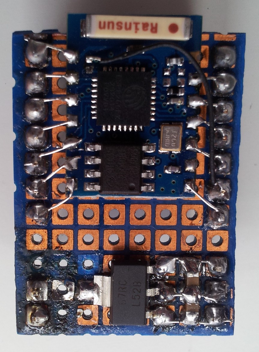
I built a breakout board for the ESP-03. it brings out the pins to 0.1" pitch headers and also adds a 3.3V LDO
Although several sources list this module as having a RESET pin, it is not broken out to the headers. Is is available on a small pad near the antenna. I wired this to the NC pin next to GND.
I also chose not to breakout the external WiFi antenna pin at this stage.
The ESP-07 modules look very interesting. They have all the pins I need to make an wireless sensor board, including:
- RESET and GPIO16 - to allow deep sleep mode
- ADC pin - to monitor battery voltage
- Other GPIOs to connect sensors.
-
Demo Apps
11/21/2014 at 05:19 • 0 commentsI wrote some demo apps based on the SDK. They are available on github https://github.com/mattcallow/esp8266-sdk
There are 7 so far:
01blinky - simple blinking LED on gpio2
02blink2 - as above, but using timers
03helloworld - Guess what this one does! (Connect to the device at 9600 baud after programming)
04sysinfo - prints out some system information (again connect at 9600)
05i2cdemo - This one is not working yet. I've copied the i2c_master files from the IoT example, but still needs more work
06thingspeak - This one actually uses WiFi! It will connect to thingspeak and update a channel with an internal counter. Optionally, it can be configured to use the thingspeak talkback commands to remotely control an LED on gpio2
07switch - basically a copy of the IoT example - a work in progress. I plan to simplify this somewhat
 Matt Callow

