To make the experience fit your profile, pick a username and tell us what interests you.
We found and based on your interests.
DSC_33860209.jpgFully populated Tiny020 with ZIF programming socket, solder sideJPEG Image - 2.07 MB - 02/10/2018 at 04:16 |
|
|
DSC_33840209.jpgFully populated Tiny020 with ZIF programming socket, component sideJPEG Image - 2.42 MB - 02/10/2018 at 04:15 |
|
|
Tiny020.bomPart list for Tiny020 pc boardbom - 2.33 kB - 02/10/2018 at 02:04 |
|
|
T020bugv009.zipMonitor/debugger for Tiny020. File is assembled withQuelo assemblerx-zip-compressed - 83.95 kB - 02/06/2018 at 03:06 |
|
|
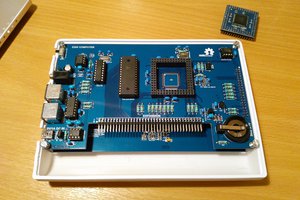
DSC_22050302.jpgTiny020 bare pc board, component sideJPEG Image - 495.39 kB - 02/06/2018 at 02:57 |
|
|
Added a pair of 7-segment displays to help me with debugging of software. The display is compatible with EASy68K hardware display trap 15/task 32, except there are only 2 displays instead of 8. Also implemented the ability to program the flash in-situ, so now I can reprogram the boot flash without removing it. I'm not putting away the flash programmer yet, just in case the newly programmed boot have fatal bugs and won't even boot. Tutor v1.3 will now run on Tiny020 using the existing trap service routines. Only a few modifications are needed: org the program to RAM base address ($100000 in this case); copy the trap #15 entry point from boot flash to RAM ($BC to $1000BC); and change vector base register to $100000. Tutor code is relocatable and with 68020's relocatable vector base register, it can be relocated and run anywhere. Very cool.
The next step is to revive my pc board layout tools so I can put this design in pc boards. I want to add the floating point coprocessor and include EASy68k hardware display as a permanent features of Tiny020, and it is too much work to hand-wire them.
Hand wired the schematic into a prototype board and this is what it looks like.
I'm confident about the 68020 and RAM chips since they are new from proven stock so they are soldered directly to the board. I'm not quite sure about the 68681, it was a pulled part from unknown board and the legs were all bent, so I socketed it. I'm also worried about 74LS138 not being fast enough to decode addresses for zero-wait state access, so they are socketed to be replaced with 74FCT138, if necessary. The flash is in a ZIF socket for ease of reprogramming.
Since I've already developed a monitor/debugger for the Tiny302, the 68020 should be able to execute them with a minimal modification, I programmed that into flash and power up. That works, I have a working monitor/debugger to work with. The design works, and I have a whole list of to-do's for the Tiny020. The top of list is a visual indicator to help me with debugging and code development.
Motorola has published an apnote, AN1015, describing a minimum 68020 system. Looking at it with today's better components, the appnote called for more parts & greater complex than is really necessary. I would rather do without PLD or CPLD--it tends to muddle up the design concept, and a through-hole design is easier to build, study and revise. The first iteration is just the CPU, flash, RAM, DUART and few TTL logic, about $30 of parts plus a prototype board. The basic design has room for a floating point coprocessor, two more memories or I/O which can be added later.
68020 instruction set is a superset of the 68000 instructions, so EASy68K tool chain is more than adequate to build a working system. The coprocessor instructions, when I get there, can be dealt using macros. My goal is to make a simple 68020 SBC that uses EASy68K trap services.
The schematic is a simplified version of AN1015.
Create an account to leave a comment. Already have an account? Log In.
https://www.retrobrewcomputers.org/doku.php?id=builderpages:plasmo:tiny020pcb
It is an old design, but I believe the pc board worked well
What are your plans with this PCB? I mean, what software are you going to run on it?
I have no specific software plan other than a better monitor/debugger. I'm looking at IDE68K tool chain which supports 68020 with assembler & C compiler so that may be a good tool for this board. I have ported CP/M 68K to 68000-based computers successfully, but the binary may not work with 68020. CP/M68k source is available in C so there is a chance it can be recompiled for 68020.
I won't try Linux on this board. I do have a 68030 design that I will post in a couple weeks. It has memory management and more memory (32Meg) so is more appropriate for Linux.
Many years ago, I talked with the guy that developed the Godbout Computing 68020 board. He said it ran the stock CPM68K, but the interrupt stuff is different enough that he never set it up to run interrupts.
it is perfectly fine to run CPM68K without interrupt if your device can work without interrupting. CPM68K polls the serial port so no need for interrupt there. Floppy controller probably will need interrupt support.
Become a member to follow this project and never miss any updates

 Plasmode
 Kn/vD
Kn/vD
 FloppidyDingo
 Tobias Rathje
Hi, may I kindly ask if you produce a PCB for this SBC ?