Close
0%
0%

uBBB 32u4

A dev board for the ATMega32u4

Similar projects worth following
A while back Warren and I designed a breakout / dev board for the ATMega32u2 (a very nice microcontroller which has native USB functionality, but does not have a through hole part for easy prototyping). The original uBBB was also a test for SMD soldering, as we had not done that before.

Fast forward to now: the uBBB boards have been used in various projects, and the itch for something new is here. More importantly, the 32u4 is now available in TQFP packaging! In addition to having more I/O pins, it also has an ADC, and is only $1 or so more.

This project documents the process of this dev board build.

(uBBB stands for 'Micro Bare Bones Board; this is a play off of an early Arduino-compatible board that I used in the past and liked for its simplicity: the RBBB - Really Bare Bones Board - from http://moderndevice.com)

As with most of my dev boards, I try to keep things simple but functional. This board includes:

  • a Mini USB B connector along with all required USB hardware (just plug it in, and you are good to go)
  • a RGB LED for status / debugging
  • all required components such as pullups on /RST and /HWB, decoupling capacitors, crystal, etc
  • 800 mil wide, 100 mil pitch, breadboard compatible holes for pins
That's it. No frills, no 50 mil spaced headers, just raw USB-compatible goodness.

  • Rev 1.1 Soldered and Working!

    The Big One05/26/2015 at 19:18 0 comments

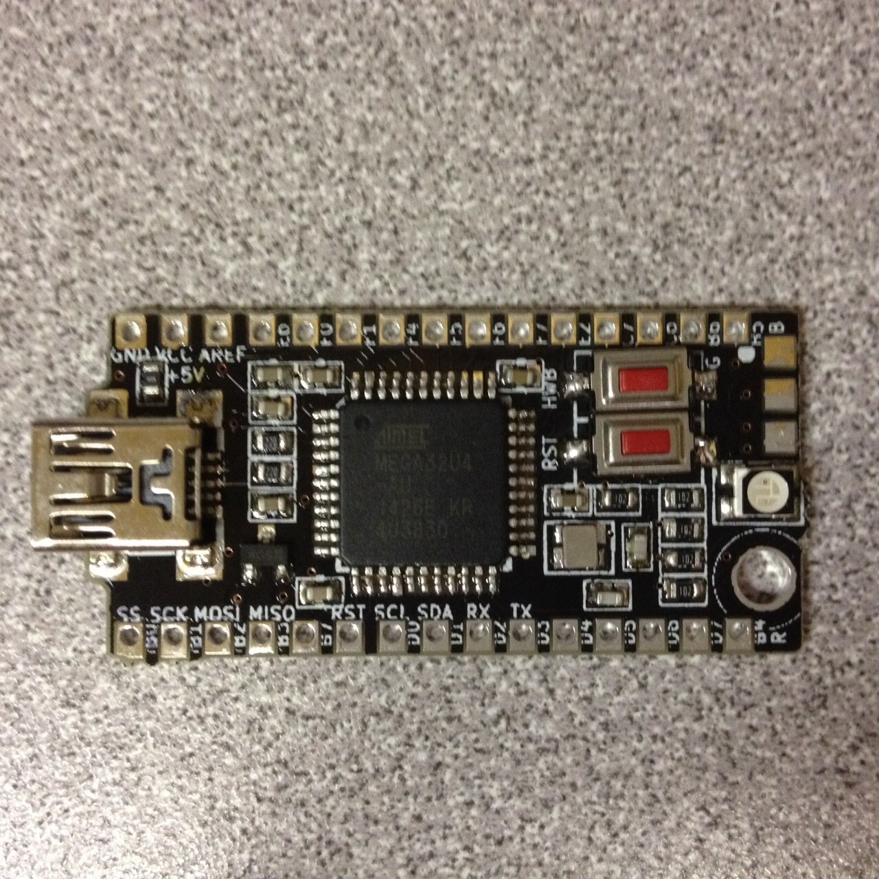
    The Rev 1.1 boards arrived a few weeks ago, but I have been too busy with other projects to update this log. Well, here we are now.

    The new boards are pretty much perfect: the only error remaining is that the crystal's silkscreen is rotated 90 degrees from what it should be (you can see this in the image; the crystal is positioned with the long side vertical, whereas on the silk screen the long side is horizontal).

    At this point I can solder one of these guys up in just about 30 minutes... not bad at all for a toothpick + heat gun job. :-)

    The soldered board is shown below. Enjoy!

  • Rev 1.1 Ordered

    The Big One04/14/2015 at 17:40 0 comments

    I panelized UBBB32u4 Rev 1.1 on my bench power supply PCB order last week. I hope for them to arrive early in May.

    The UBBB (plus power supply) boards can be ordered from Dirty PCBs.

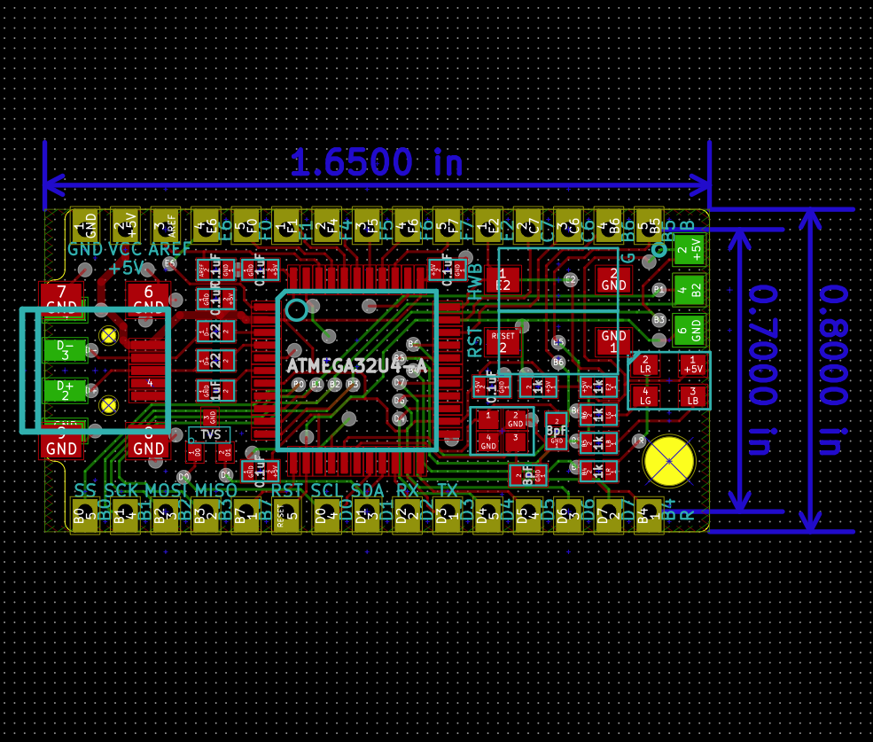
    The board image is below:

  • Revision 1.1

    The Big One03/04/2015 at 22:58 0 comments

    We have pretty much finalized the changes to Rev 1.1. In addition to the gerber bugs mentioned in previous logs, we have made the following changes:

    • Enlarged text for easier readability
    • Improved the mounting holes
    • Added an optional TVS diode on the I2C lines (I have managed to kill the I2C lines on AVRs in the past, and I suspect ESD damage... apparently these lines are more susceptible to ESD than other pins)
    • Minor routing improvements

    The updated board can be seen below:

    I am planning on batching this on my next PCB order (which will likely be for my power supply boards)

  • First UBBB 32u4 is Alive

    The Big One01/09/2015 at 16:31 0 comments

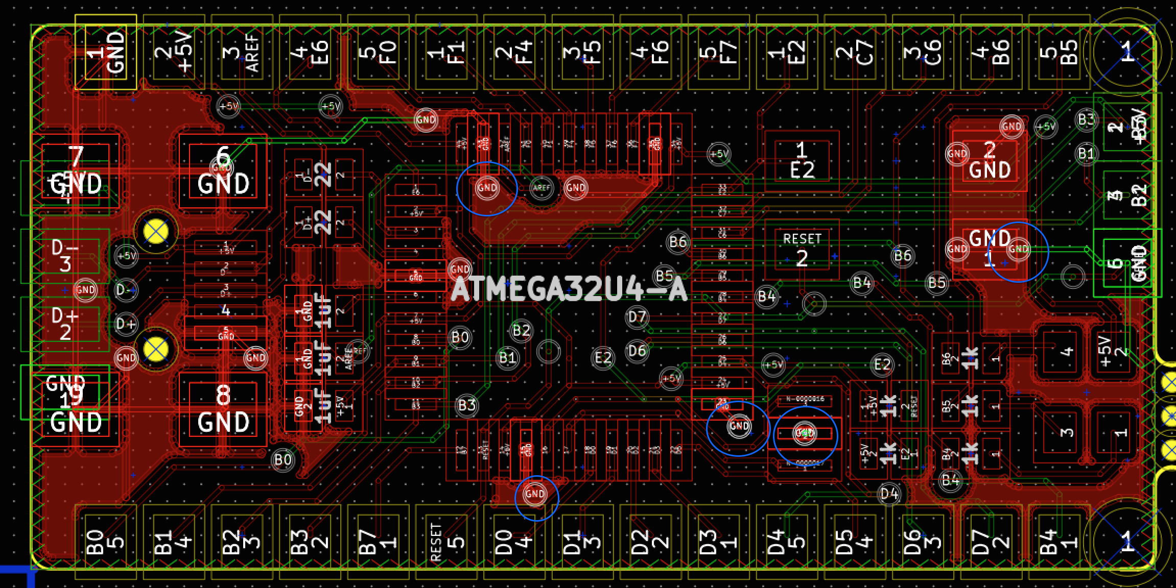
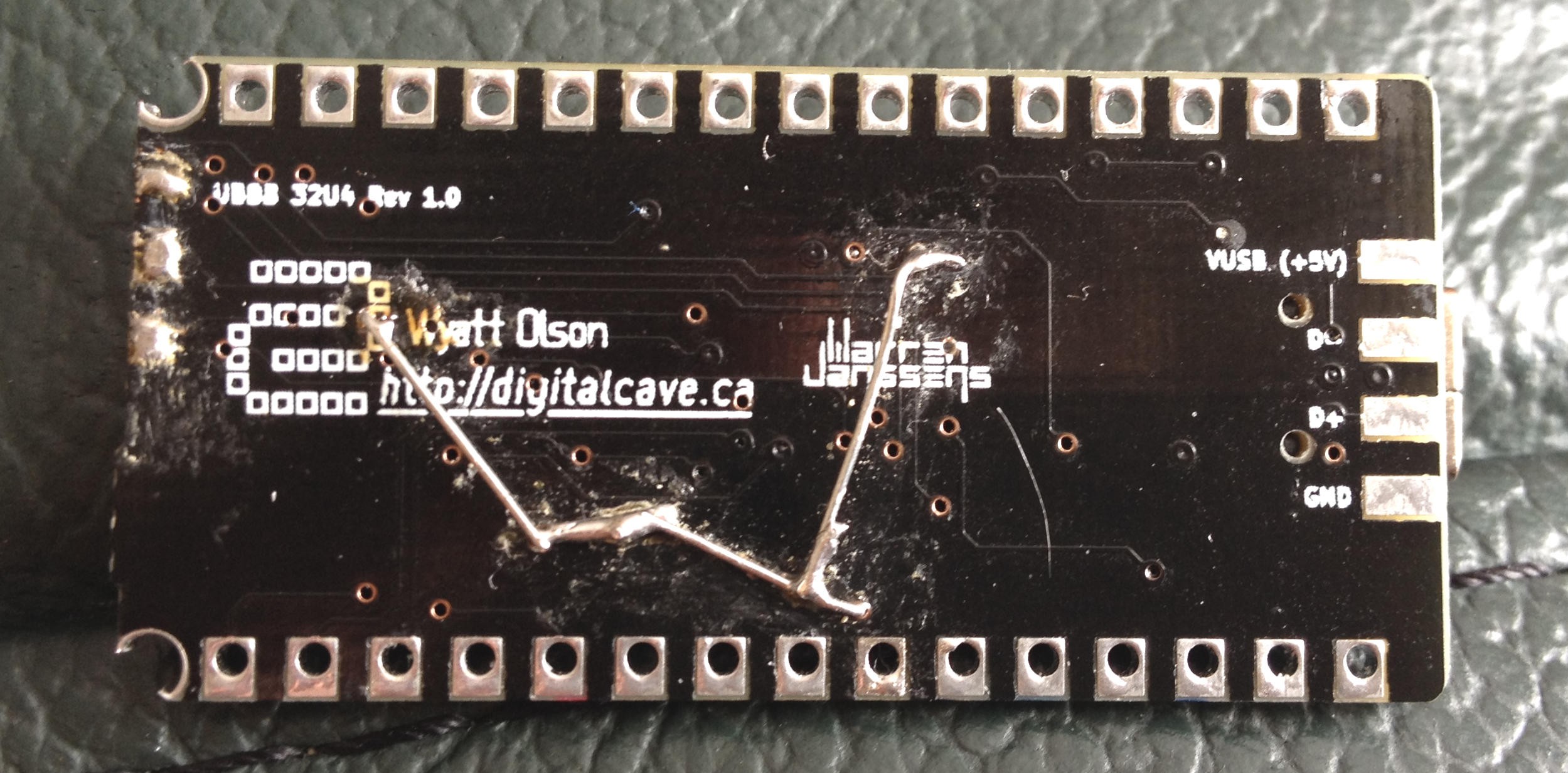
    Yesterday my 16MHz resonator finally arrived, so last night I soldered up the first UBBB 32u4 board. The SMD stuff was easy enough (took about 30 minutes). Trying to fix that stupid ground plane bug was much harder (took over an hour) - I ended up using a very thin wire from a through hole resistor that would fit inside the vias. I would then tin the lead, push onto the via (from the back of the board), and let the wire get soldered in the middle. I would then bend the wire over to the next closest GND via, and repeat. There are at a minimum 5 vias that must be done like this (diagram viewed from the front, with required GND vias circled in blue):

    After getting everything soldered up and verified with my multimeter, I plugged it into the computer... and nothing. AVR Dude was showing invalid device signatures:

    avrdude: initialization failed, rc=-1 
    avrdude: AVR device initialized and ready to accept instructions
    avrdude: Device signature = 0x000000 (retrying)
    avrdude: Device signature = 0x000000 (retrying)
    avrdude: Device signature = 0x000000
    avrdude: Yikes! Invalid device signature.
    avrdude: Expected signature for ATmega32U4 is 1E 95 87
    

    By this time it was after midnight, so I went to bed.

    The next morning I woke up early and checked continuity on everything again; this time checking from the actual chip to the destination (in my case, the ISP headers). Sure enough, the SCLK pin on the ISP was not touching the pad properly. I added a bit more solder onto that pad, and I got 'make readfuse' to work!

    I ran into another problem when trying to write the fuses, but it turns out that the u4 chips come with the fuses locked, and you need to do a full chip erase (-e flag) before writing fuses. See this post which got me pointed in the right direction here.

    I then uploaded my blinkylights program, and sure enough, the blue light (B4) started flashing at 0.5Hz as specified. The chip looks to be working!

    Next I downloaded LUFA, modified the DFU bootloader to use the lights on this board, and flashed the custom DFU bootloader.

    Finally, I uploaded the blinkylights program again, but this time using dfu-programmer. Sure enough, it still works.

    For those who have ordered their own PCBs for this board, you can download the sample program + custom bootloader from GitHub.

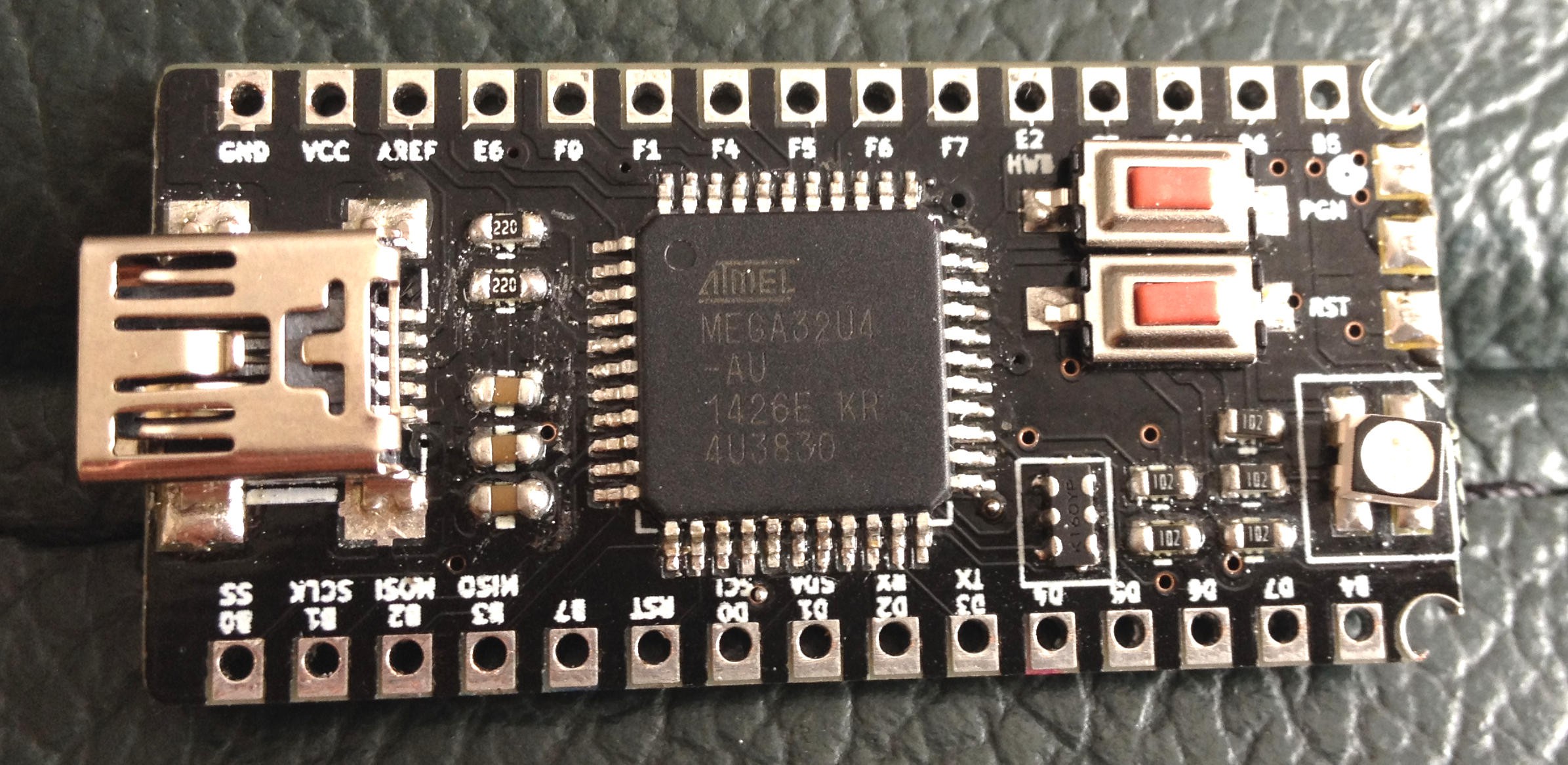
    Pictures of the front (reasonably pretty, with the exception of the slightly tilted LED and some flux) and back (hideously ugly hack) are below:

    At this time I am going to declare the UBBB 32u4 a success. Yes, there are some bugs on the rev 1.0 board, but they are well underway to being fixed in rev 1.1, and even with the bugs, you can still work around them and have a working 32u4 dev board. (And from now on, I am going to be even more OCD when checking the final panelized boards in KiCad... if anyone knows of a way that you can panelize a board in KiCad and still use DRC and such to verify the boards (even though there may be multiple boards with the same net names), please let me know.

    Cheers

  • Boards Arrived

    The Big One01/07/2015 at 02:47 0 comments

    The Rev 1.0 boards arrived today. There are a couple of other bugs which I can now see, which I have resolved in the Rev 1.1 model:

    1. Solder mask covering the rear of the ISP headers
    2. Enlarged the mounting holes a bit (two-fold purpose: to let them accept a \#4 screw, and to get rid of the scraggly edge that was left behind when the fab house didn't cut quite as deep into the edge as I had thought they would)

    I am still planning on soldering up one of the AVR boards (with appropriate jumpers to fix the broken ground plane), but I need to wait for some more components to come before I can do that (specifically, a high accuracy SMD resonator and some 1k resistors)

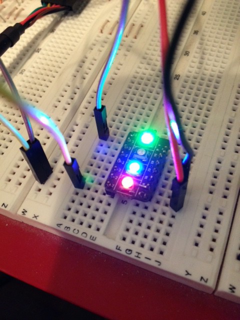
    The LED breakout board is working well, at least once I put a small jumper between VCC LED pad and VCC pin (lesson learned: do not modify a board after it has been added to a panelized project, since you can no longer run DRC against it). You can see the jumper right beside the red light in the picture below.

    (Showing three of the lights on. Sorry for the horrible quality iPhone picture!)

  • Bugs in Rev 1.0

    The Big One01/06/2015 at 19:09 0 comments

    We have still not received our boards yet, but someone else has ordered their own copy, and has reported that there are some bugs in the rev 1.0 version. The most glaring issue is the lack of GND flood fill on the back of the board (the zone is there, but had been reset at some point before ordering). This means that we will have to dead-bug 6 wires between vias on the back to get things working properly. Boo!

    A rev 1.1 board is well underway with the following changes (see git for details):

    1. Actually fill the GND plane this time (gah!)
    2. Use a crystal + caps instead of a resonator. While I believe that we have selected a resonator that will work with USB, apparently crystals make for more stable USB communications.
    3. Add more decoupling caps (we now have one 0.1uF for each VCC / AVCC pin, with a 1uF on UVCC).
    4. Fixed the LED footprint to use some dirt-cheap RGB LEDs from eBay rather than the more expensive Cree LED (same footprint, but different pinout). See http://www.ebay.ca/itm/330833693803?ssPageName=STRK:MEWNX:IT&_trksid=p3984.m1439.l2649 for the LEDs which we are now using.
    I'm not going to order this new board until I get my original PCB order (hopefully this week), and have verified that everything else is working as it is supposed to.

    Cheers

  • Ordered PCBs

    The Big One11/27/2014 at 21:28 0 comments

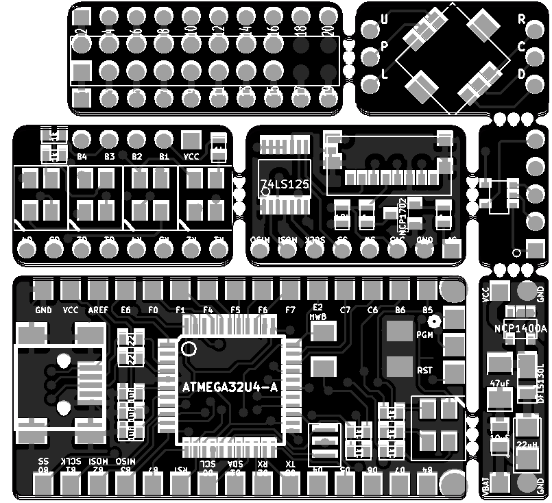
    We just ordered the PCBs today. Included on the same board are a number of other breakouts. See the DirtyPCB Store link for ordering info and breakout details.

    The dirty rendering of the board is below:

View all 7 project logs

  • 1
    Step 1

    PCB Rev 1.1 Errata:

    • The crystal silkscreen shows it as being rotated 90 degrees from what it should be (at least for the crystals I am using... I am not sure if there are standards on this or not). Be sure to verify which pins on your crystal are supposed to be GND, and which pins on the board are supposed to be GND, and rotate the cystal so that these are aligned.

View all instructions

Enjoy this project?

Share

Discussions

Michael Vowles wrote 10/26/2015 at 23:35 point

Could you see any problems in using a cheapy USBAsp programmer for this thing?

  Are you sure? yes | no

The Big One wrote 10/27/2015 at 14:58 point

No I would expect that would be fine.  Honestly you could get by without programming it with a custom bootloader at all.  The upside to that approach is simplicity (no ISP programmer required); the downside would be that you lose out on the RGB blinkylights to indicate that you are in programming / bootloader mode, and that you would have to adjust the clock speed on all programs (one liner, so no big deal).

It may be best to assemble it first, verify that things work with the default bootloader, and then program the custom bootloader if you want the blinkylights.  To see if it works, there are is a simple blinkylights sample program in my repository at https://github.com/thebiguno/microcontroller-projects/tree/master/samples/avr/atmega32u4/blinkylights

Cheers

  Are you sure? yes | no

Michael Vowles wrote 12/12/2015 at 02:26 point

Silly me, I didnt realise you could just program this straight up with FLIP...

  Are you sure? yes | no

Michael Vowles wrote 12/12/2015 at 02:26 point

Silly me, I didnt realise you could just program this straight up with FLIP...

  Are you sure? yes | no

zoobab wrote 10/09/2015 at 14:20 point

Could you try to flash opendous-jtag firmware for the 32u4 ?

http://www.zoobab.com/arduino-leonardo-atmega32u4

And tell me if it works?

  Are you sure? yes | no

Johannes Larsen wrote 01/08/2015 at 16:55 point

I have noticed that the different breakout boards use different pin header hole sizes. The 32U4 breakout, the boost convert and the center rows of the ribbon cable breakout use 40mil holes. All remaining holes are 32mil, and this barely fit .1" headers (as in I need to press the board onto pins pressed against some surface or attached to a vise to avoid pushing the pins through the plastic). I have yet to try attaching pins to one of these hole which have been accidentally filled with solder then cleaned with desoldering tools, but I doubt it would be an easy task.

So are you using something other than .1" headers (e.g. something that does smaller damage to breadboards) or are do you have any other reason for choosing so small holes?

  Are you sure? yes | no

The Big One wrote 01/08/2015 at 17:08 point

That is the kicad default. I change them when I remember. That said, with standard 0.1" headers, I have had no problems fitting them into either sized hole just by hand, not using any tool to assist. Yeah the 32 mil ones are a bit tight, but I have yet to find a pin that doesn't fit (and I have sourced my pins from all over the place, including Digikey and eBay, so they are not all just one manufacturer).

I am (slowly) building up my own set of custom KiCad libraries (located at https://github.com/thebiguno/microcontroller-projects/tree/development/lib/kicad if you are interested), and have plans to make standard pin headers with 40 mil holes. (I already have the components made up in sizes from 1 to 28 pins, the footprints will hopefully be soon).

I find that this is the biggest problem with KiCad - their assortment of libraries and footprints is haphazard at best. They have all sorts of obscure parts, and then miss something common. Even when they *do* have a component, it is no guarantee that it is correct - see for instance the SMD USB Mini connector (at least in the version I have currently). Buuuuttt..... it's still way better than Eagle! ;-)

  Are you sure? yes | no

Johannes Larsen wrote 01/08/2015 at 17:53 point

In my KiCad standard PIN_ARRAY components use 40mil holes, but the available permutations is so limited that I have created my own library[1] containing set of pin arrays with 1..16 circular pads, rectangular pads and interconnected pads (used for prototyping boards). I see your problem with the poor libraries, and I tried fixing it by using the component library from Dangerous Prototypes, but it turns out that this is generated from their Eagle components library which results in components with an inconsistent pin numbering scheme (e.g. A[node] and C[athode] for diode pins) which differs drastically from the KiCad numbering scheme, so you have to triple check the pin ordering of each component. And as such I consider dropping their entire library despite the fact that they have great graphics (e.g. Micro usb connector).

I have actually managed to get boards manufactured where the "nice" silk screen visualizing diode direction for some Dangerous Prototype component was reversed from the schematic symbol, so you would need to solder diodes back to front.

[1] https://github.com/johslarsen/lib_kicad

  Are you sure? yes | no

Johannes Larsen wrote 01/03/2015 at 22:33 point

I stumbled accross this project in the DirtyPCB Store, and since I had a few Atmega32U4 laying around I ordered a protopack some while ago. A couple of days ago the board arrived and I soldered components onto the board.

Long story short, there exists bugs (see list at the end) which you seem to be aware of, because the KiCad schematic and layout images differs from the DirtyPCB gerber preview. So I am wondering whether you are planning to do another run or if it would be possible to get a copy of the KiCad project and/or updated gerber files.

Observed bugs:

The buttons that should connect HWB and RST to GND is connected to a flood plane that is not connected to GND

No caps between oscillator and GND

Common andode for the RGB LED is on an incorrect pad when aligned with the pin marker. NOTE: The DirtyPCBs have it on pin 1, the revised layout have it on pin 2 and the RGB LED breakout board have it on pin 4 along with my RGB LEDs, but this can be worked around be rotating the LED.

RGB LED breakout board have a VCC pin, but these is not connected to the anything.

  Are you sure? yes | no

The Big One wrote 01/03/2015 at 22:49 point

My boards have not arrived yet, so you are at an advantage here :-P
The DirtyPCB preview is a bit off, but I didn't think that was indicative of any problem (as they don't always look identical).
Reported bugs are addressed below:


1) HWB not connected to GND - this should be connected, the flood plane on the front is connected to the flood plane on the back with four vias. Do you see no continuity when using a meter, or are you just visually inspecting it?


2) No caps between oscillator and ground - that is by design, this is meant to use a resonator, not a crystal. I am planning on using part http://ca.mouser.com/Search/ProductDetail.aspx?R=PRQC16.00SR1010V00Lvirtualkey58110000virtualkey581-PRQC16.00SR1010V (resonator with enough accuracy that it should work with USB 1.1 speeds)


3) I saw this bug a few days after I ordered. There are a few different LEDs which can be used; the one which is in the design right now should be http://www.digikey.ca/product-detail/en/CLVBA-FKA-CAEDH8BBB7A363/CLVBA-FKA-CAEDH8BBB7A363CT-ND/2650500 . This one should work correctly. (I had wanted to use a different package since I had bought a bunch of dirt cheap ones off of eBay; luckily the one I want to use can still be used by rotating the LED. I need to verify this before soldering). Just check everything out with a DMM before soldering.


4) On the 4x RGB LED breakout, the VCC pin is connected to pin 1 of each LED. As in response 1, are you seeing no continuity with a DMM, or are you just visually inspecting it? There are 3 vias which should connect it through.
I wonder if the fab house didn't properly connect the vias? That is very annoying if that is the case... :-(


You can see the panelized board at https://github.com/thebiguno/microcontroller-projects/tree/47a4a5314f2d2cc3db8d2db4c6288e78091556d9/projects/temp . The various source projects (including schematics) are in the repo at this same commit (the UBBB_32u4 is still there at head revision, but some of the minor breakouts have been deleted after the order, so look at SHA 47a4a5314f if you want to see everything)


Please let me know what you find here... and when I get my boards (I am hoping for next week), I will be able to reply with a bit more confidence.


Cheers

  Are you sure? yes | no

Johannes Larsen wrote 01/04/2015 at 01:06 point

1),2), would be solved by a GND flood fill on the bottom copper layer. My workaround:

USB and capacitors are connected to GND

Some of the chip pins (35,43) are already connected to GND, and ignoring the remaining pins.

Soldering a jumper wire between the GND side of one of the buttons and the USB shield (i.e. GND) solves the buttons and ISP header.

My resonators[1] works without bothering to connect the GND, see pictures [3]..[6] for the impact.

3) This is a problem with different LED packages, and I do not see a
simple solution. For my LEDs[2] the workaround is to solder it on
rotated a quarter turn counterclockwise. The datasheet for the ones you found on digikey states (page 7) that its anode on pin 2, so it would need to be rotated a quarter turn clockwise.

4) There is no traces connected to the VCC pin, which is clearly visible in the DirtyPCB images. Pin 4 on the LEDs are connected together, and the remaining pins are connected correctly for my LEDs[2], so workaround is to connect pin 4 of LED 1 to VCC.

5) NEW. I noticed the pads alongside the board by the LED is a standard ISP header, however its pads on the bottom side of the board are covered by silkscreen. Workaround is to scrape of
the silkscreen.

[1] http://www.ebay.com/itm/121454862851

[2] http://www.ebay.com/itm/330833693803

[3] XTAL1 without GND

[4] XTAL2 without GND

[5] XTAL1 with jumper wire to GND

[6] XTAL2 with jumper wire to GND

EDIT:

noticed reply button, so reposted as reply, added links not just the references to them and reordered links such that images is on the bottom in case images are inlined

  Are you sure? yes | no

The Big One wrote 01/04/2015 at 01:11 point

3) These LEDs are not the ones from Digikey; they are ones from eBay: http://www.ebay.ca/itm/330833693803?ssPageName=STRK:MEWNX:IT&_trksid=p3984.m1439.l2649 (These are the ones that I had meant to use for the uBBB, but messed up).
4) Not sure about that. Looking at the KiCad files, there should be a trace there. :-(
5) Good to know, thanks for the info.

  Are you sure? yes | no

Johannes Larsen wrote 01/04/2015 at 02:26 point

4) I checked out the project at 47a4a53, and on my side there does not seem to be any trace from VCC on the LED board

6) NEW. The optimistically placed screw holes at the edge of the board are a bit too close to the edge, so on most of my boards their edges towards the board edge are missing or will break off by as little as a sneeze. The reimainder of the screw hole may possibly be press fitted between the screw head and some other surface (e.g. nut).

  Are you sure? yes | no

The Big One wrote 01/04/2015 at 02:37 point

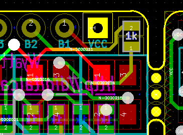
4) OK, that looks like another bug which happened during the panelizing process. Again, the easy fix would be a deadbug jumper from VCC to the pad 1 directly across from it (see highlighted net).

(This was the first time that I panelized this many boards in one. I think my process needs to be re-visited. Have you any experience panelizing boards in KiCad? I am curious if there is any way other than the "File -> Append Board, then manually move things around" way of doing things.)


6) The screw holes were actually meant to hang off the side; in fact, if there is anything there at all I am surprised (and a little disappointed). The thought was that the two of them together would be sufficient to hold the board in place, assuming that both screws were used.

  Are you sure? yes | no

Johannes Larsen wrote 01/04/2015 at 02:59 point

I have never panalized boards in KiCad. The only boards I have
created have been designed around the 5x5 cm price mark for DirtyPCB.

Of the boards that had any material on the outer part of the screw holes it is removable by hand or just use any side cutter. I measeured the edges from one of the broken of piece with a micrometer and its around 0.05mm, which corrosponds to the reimainder of the edge cut in Kicad, so the boardhouse probably cuts to the outermost edge of the board edge. Using a smaller width (e.g. 0.001) would probably cause them to cut closer to the center of the board edge and thereby removing all the material.

EDIT:

reposted as reply instead of new comment

  Are you sure? yes | no

The Big One wrote 01/07/2015 at 02:34 point

5) I was confused by your comment on the ISP header silkscreen, as there was no silk screen around that area. However when the boards came today, I realized it was solder mask that was covering the bottom. *That* makes no sense to me... I have used this component in the past for other boards, and it has worked. I have no idea why it didn't this time. Looking at the KiCad module, I see that the rear pads are marked as front, so I see why it happened, I just don't know when the component was changed.

Anyway, thanks for your help with the troubleshooting. I apologise that (at least the main AVR board) didn't work out for you. :-( Hopefully you will at least find some of the other breakouts to be useful.

  Are you sure? yes | no

Johannes Larsen wrote 01/07/2015 at 22:55 point

This boards are much better than any standard TQFP breakout board, so I am happy.

EDIT: reposted as reply, goddamn user interface

  Are you sure? yes | no

The Big One wrote 01/09/2015 at 06:59 point

Well this is frustrating.


I got the last of the components that I was waiting for today (the resonators), and so I soldered everything up. The worst part was getting the grounds connected, but I ended up using thin through hole resistor wire that fit inside the vias (I tinned it first, then put it in with an iron). All grounds are connected... but the thing still can't be seen by the programmer. It just says:


avrdude: initialization failed, rc=-1
avrdude: AVR device initialized and ready to accept instructions
avrdude: Device signature = 0x000000 (retrying)
avrdude: Device signature = 0x000000
avrdude: Yikes! Invalid device signature.
avrdude: Expected signature for ATmega32U4 is 1E 95 87


I am wondering if I burnt the AVR (I had originally soldered it to another board, then desoldered using a heat gun, and re-soldered again using the heat gun). Looking at the SPI interface using a logic analyzer, I see MISO as zero (well, actually it is floating since if I touch it I see all sorts of noise... but regardless, the AVR is not driving it in either direction).

Looking on my scope I see activity on both XTAL pins (my scope is a 10MHz analog one, so I can't see much, but I see definite 'fuzz'). I can't think what else I can test... and besides it is way past my bedtime.


I'll give myself a bit more time for thinking, but if I can't get it working I will have to desolder it and throw another chip on... and cross my fingers that it works that time. :-(

  Are you sure? yes | no

The Big One wrote 01/09/2015 at 16:11 point

Yay! It turns out the problem was a bad connection on SCLK. I can now successfully read fuses.


I ran into another problem when trying to write the fuses, but it turns out that the u4 chips come with the fuses locked, and you need to do a full chip erase before writing fuses. See http://electronics.stackexchange.com/questions/37476/failing-to-write-atmega16u4-fuses-with-avrdude for the post which got this working for me.


I then uploaded my blinkylights program, and sure enough, the blue light (B4) started flashing! w00t!


I then downloaded LUFA, modified the DFU bootloader to use the lights on this board, and flashed the custom DFU bootloader.


Finally, I uploaded the blinkylights program again over dfu-programmer. Everything is working properly.


If anyone is interested, they can download the sample program + custom bootloader from GitHub: https://github.com/thebiguno/microcontroller-projects/tree/development/samples/avr/atmega32u4


Cheers

  Are you sure? yes | no

leandro wrote 07/30/2015 at 19:10 point

i had the same problem last year trying to burn the bootloader to the atmega32u4 in a board i made similar to yours. I couldn't solve it and until now i didn't have time. 

Maybe i can give it a second chance with your design..

  Are you sure? yes | no

The Big One wrote 01/03/2015 at 22:58 point

Hmm, looking at it again, it looks like problems 1 and 2 with the uBBB are due to the rear ground plane not being filled properly. GRRRRR!!!! I normally route boards with the ground planes hidden, so I didn't see that when I submitted the boards.


The good news is that all is not lost.


You can connect the front ground plane in all required places by jumpering at a minimum 6 vias together. You can look at the KiCad files in PCBNew to see which ones.


I apologize for missing that 'minor' detail :-( Sigh. Such a n00b :-(

  Are you sure? yes | no

Similar Projects

Does this project spark your interest?

Become a member to follow this project and never miss any updates