Michael O'Toole
-
August 2015
08/06/2015 at 05:41 • 0 commentsDisplaying sensor status:
I have started work on the web interface to receive sensor data and process it accordingly. I have chosen to set up a local server as this will provide a nice looking interface independent of the OS and simple to modify and update.
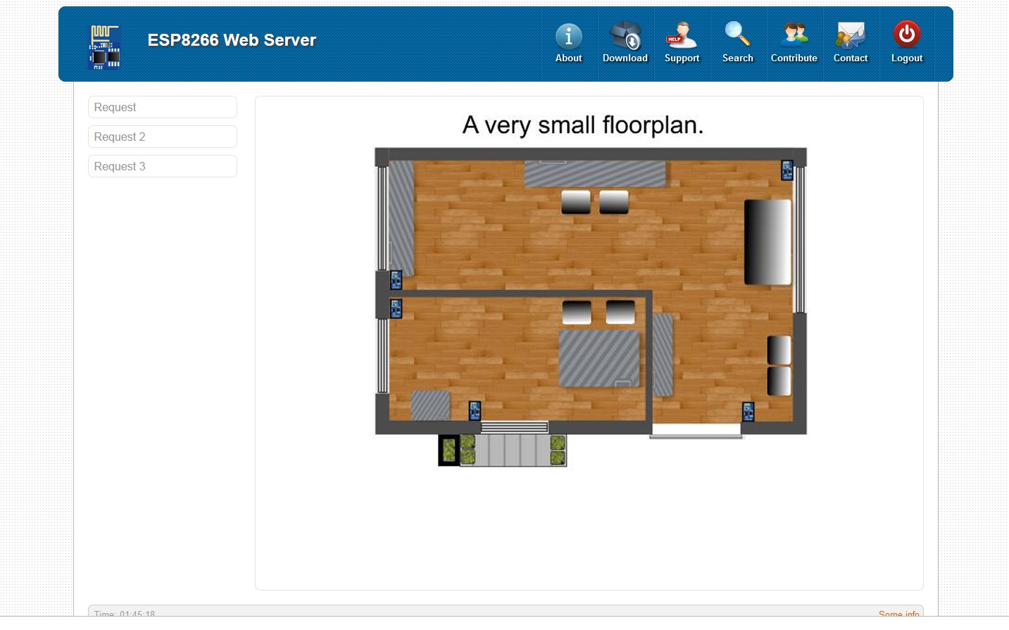
Example:
![]()
Here I'm using a simple image to represent the layout of a small house. Each window and door is protected by an inertia sensors. Should anyone try to enter the house the corresponding sensor will trigger and send a signal via WiFi to the server.
While each sensors is designed to operate autonomously and could activate an alarm directly, the inclusion of a web interface gives us the added ability to further analyse the alarm condition and depending on a variety of circumstances take alternative action...
In its simplest form the web interface might just be used to display information but as you can see from the above example, it could be expanded to almost anything...
-
July 2015
07/30/2015 at 01:38 • 0 commentsI've been busy with some long standing projects but have managed to do some testing with inexpensive piezo sensors in order to determine if they are suitable (and reliable) as the main sensing device for the project...
Inertia Sensors:
- Capable of detecting the slightest vibration...
- Must be consistent over various temperature ranges...
- Free from electrical/electronic induced side effects...
- Free from corrosion over an extended period...
Analysing Inertia Sensor Signals:
Having established that we will receive some signal data for even the slightest vibration it follows that we must analyse each signal both in amplitude and time (relation to any previous signal)...
A single high amplitude might signal a gross attack (glass breaking or force entry for example) and if above a predetermined level we might generate an alarm straight away... A much more common occurrance might be several small vibration in a short period (gently prying or forcing a window or door without making noise), here the analysis is a bit more tricky, after all we don't want an alarm if it's raining...
On a side note, some advanced alarm might even include a rain sensor, wind gauge and thunder sensors to augment inertia sensor analysis... we could add that too...
Implement criteria in software
On first detecting a signal we measure its amplitude and if above a predetermined level we signal an alarm condition but if below this level we record (count) and start a timer.
Should the signal be below the gross level, we start a timer and count each successive signal up to a predetermined number... If that number is exceed during the sensor time period we trigger an alarm condition...
Setting the sensors sensitivity can also be accomplished with software (during the install process) and this help remove some of the guess work but of course you can also modify sensitivity via the web interface...
A second line of defence:
As all WiFi sensors send data to a central computer it also follows that we can further analyse signals in relation to each other. For example, if several sensors in different locations appear to indicate a break in at the exact same time (within milliseconds) , we can over-ride the alarm as it's almost certainly something natural, thunder for example...
A simplified Approach:
Allowing for the fact that a central computer can do all the analysis, it follows that we could actually simplify the WiFi sensors job and instead simply pass the detection event and the level back to the central computer (after first eliminating extraneous signals locally) and not have to write more complex code...
Notes to add...
Note the sensor also signals battery low using the ADC pin...
-
Programming ESP with Arduino IDE
04/28/2015 at 11:57 • 0 commentsSee: https://hackaday.io/project/3352-esp8266-development-pcbs/log/17066-programming-esp-with-arduino-ide for updates...
Looks like we will soon be able to use the little ESP8266 as a standalone device (no additional microcontroller required) and that make the WiFi sensor so much more practical... Just write your program in the Arduino IDE, upload to ESP and off you go...
...
-
Firmware Update (902)
11/19/2014 at 16:26 • 0 commentsThere are a few way to update the firmware but for the moment as I am not writing any code I have chosen to use an executable containing the most recent firmware. I should note the little executable program's UI is in Chinese and a bit difficult to work out but as there's only one button it's not impossible...
After updating to 902, you can no longer use Putty to issue AT commands as it doesn't send CR+LF so I have changed terminals to Termite version 3.1 and it works a treat....
-
Building a development board
11/16/2014 at 17:54 • 0 commentsAt the stage where I need to program the ESP8266 and see what it's capable of... time to build a development board.
Started working on one here: https://hackaday.io/project/3352-esp8266-development-pcbs ... As you can see, my current projects are interrelated, working on one, progress all of them...
It's highly likely that the ESP's on-board controller can handle all the sensing and remove the need for the ATMega328...
-
Toolchain and Compile Tests
11/09/2014 at 16:35 • 0 commentsThe installation of esp_iot_sdk_v0.9.2 toolchain and compile tests were successful... next to upload the compiled binaries to a couple of the early modules...
Toolchain Contents: (windows)
MinGW, Python27, the ESP sdk (v0.9.1) and ESP Tool (esptool..).
All programs are installed to root (C:\) and the path has to be set for the each...
After compiling the binaries are sent using a python scrip but as I'm old and lazy so I opted for the Flash Download Tools v0.9.2 from esp8266.com... nice simple GUI...
Check the esp8266 forums (http://www.esp8266.com/index.php) for Linux/Apple information...
-
Getting Started
11/09/2014 at 05:18 • 0 commentsAs mentioned, this project is a spin-off from my Home Automation and Security project, so some work has already been completed. The next stage is setting up tools to write and compile code for the ESP8266...
The main display unit consists of a small 1.8" TFT display, ATMega328 and ESP8266 module has been built and tested... The costs of the display hardware is less than $20....
Each ESP8266 WiFi Monitor Module should cost less than $5
While any type of sensor can be used, I will use an inexpensive piezo sensors (the output of which is analyses to prevent false alarm) and a simple IR reflector (to determine if door/windows is open or closed)...