 willbaden
This tester can be broken down into a few sections:
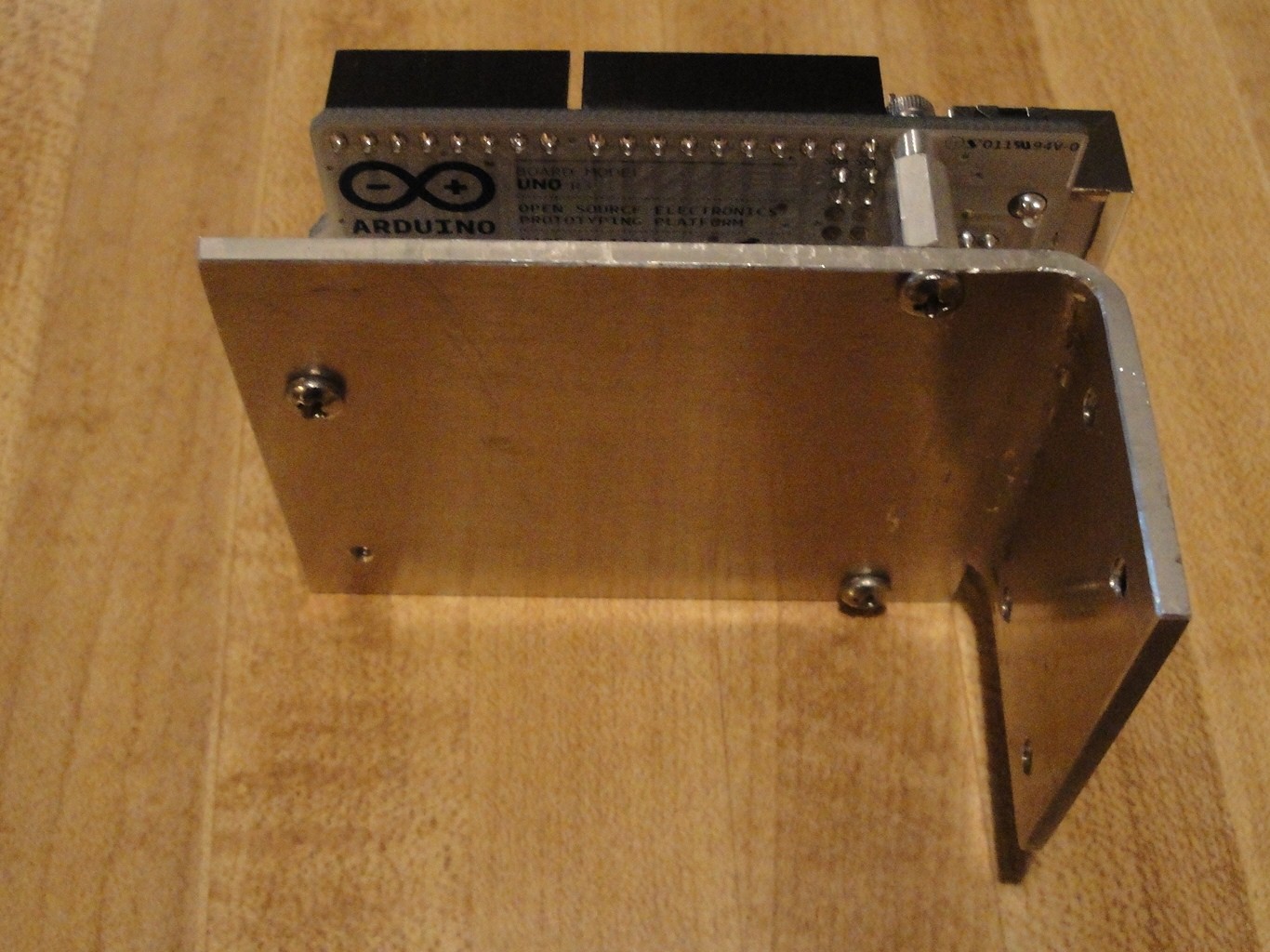
Controller (Arduino UNO)
Loads (Resistors and Heater Coils)
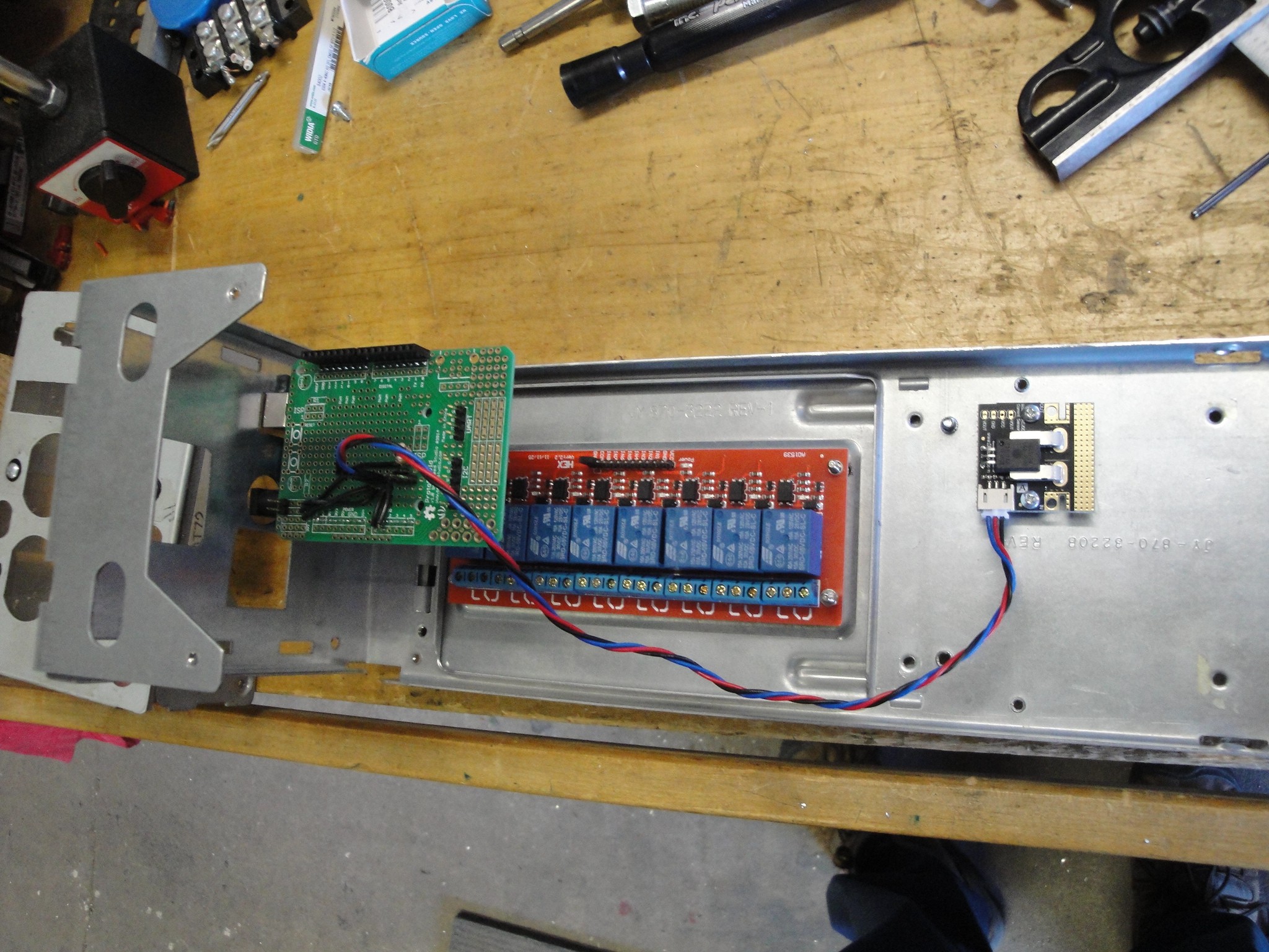
Output control (Relay Board)
Input Sensor (Current Sensor and Voltage divider)
Data Logger (Computer running software)
The controller uses an UNO. This will monitor the input sensors and control the resistor banks to apply loads to the battery. The selection of when to turn the resistor bank on or off is based on the voltage sensed and the known resistances of the loads. By placing the lowest valued resistor on bank 1, the second lowest on bank 2, the third lowest on bank 3 etc until bank 7 has the highest valued resistance. The UNO then calculates the current that would flow through with the applied voltage. If the amperage that is required (starting at 40 amps) is greater than the amperage that the resistor bank can supply, then the bank is turned on. The calculated resistor amperage is then subtracted from the last known amperage requirement. This value is saved and the next resistor banks amperage is calculated. This value is then checked to see if it is lower than the remaining current that is required. etc.

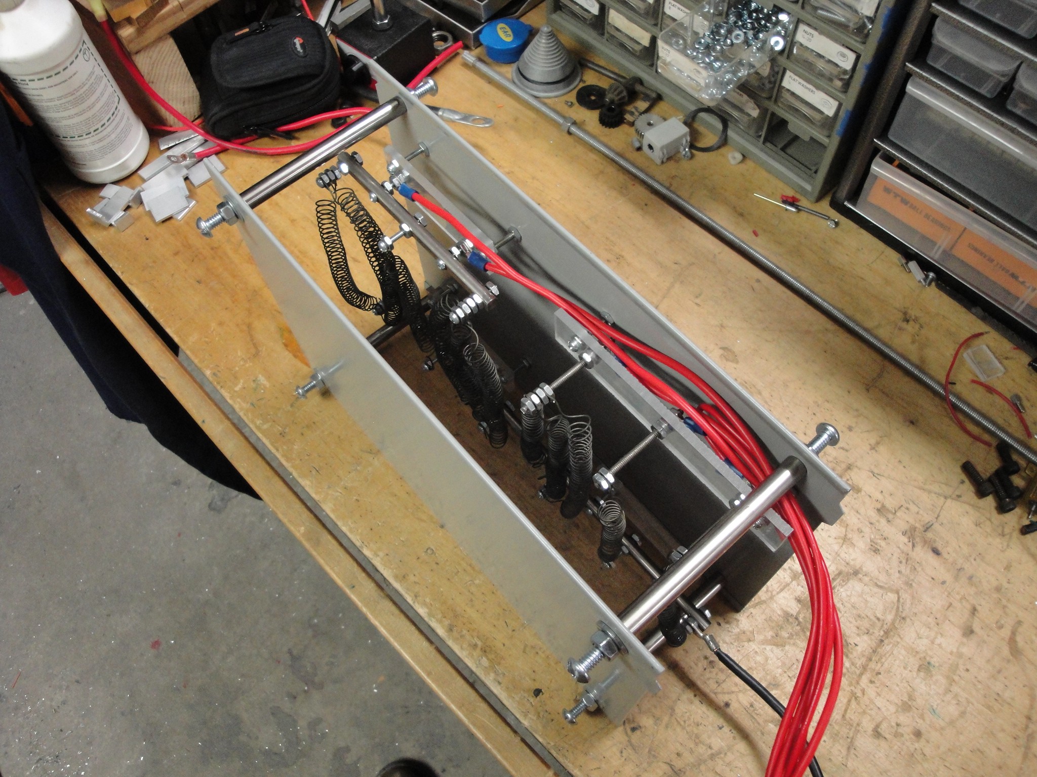
The loads that were used was a mix. I did not want to spend too much money on the wattage requirements of the resistors. Digging through my parts bin, I found some old heater coils from an old electric dryer that we fixed. The dryers coils were replaced with new coils as these old ones failed in one location. Instead of throwing them away, I held onto them and am glad that I did. By cutting them down I could get approximately 3 ohm segments that could be paralleled to create low ohm resistances that could handle the watt dissipation. One was cut down to 2 ohms, but that is pushing it to the point of glowing a dull red. Using a fan to blow across it prevents it from glowing.
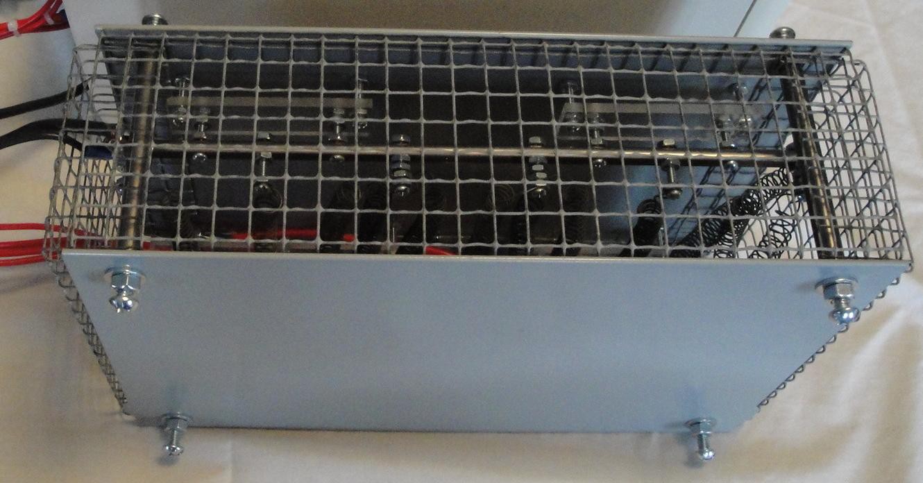
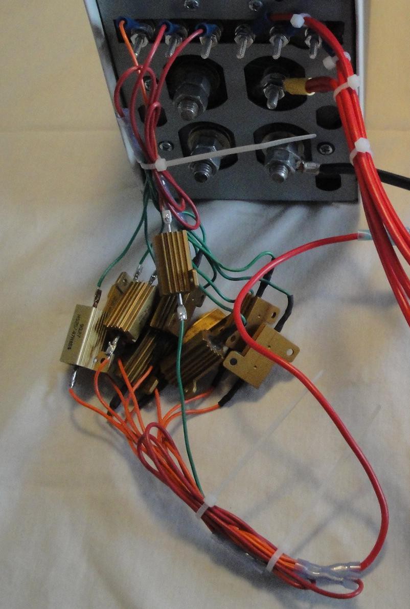
The heater coils took care of the heavy loads, while a 10 ohm and 10x 47 ohm resistors took care of the rest. 5 each 47 ohm resistors were paralleled to roughly create 10 ohms.
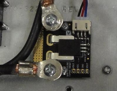
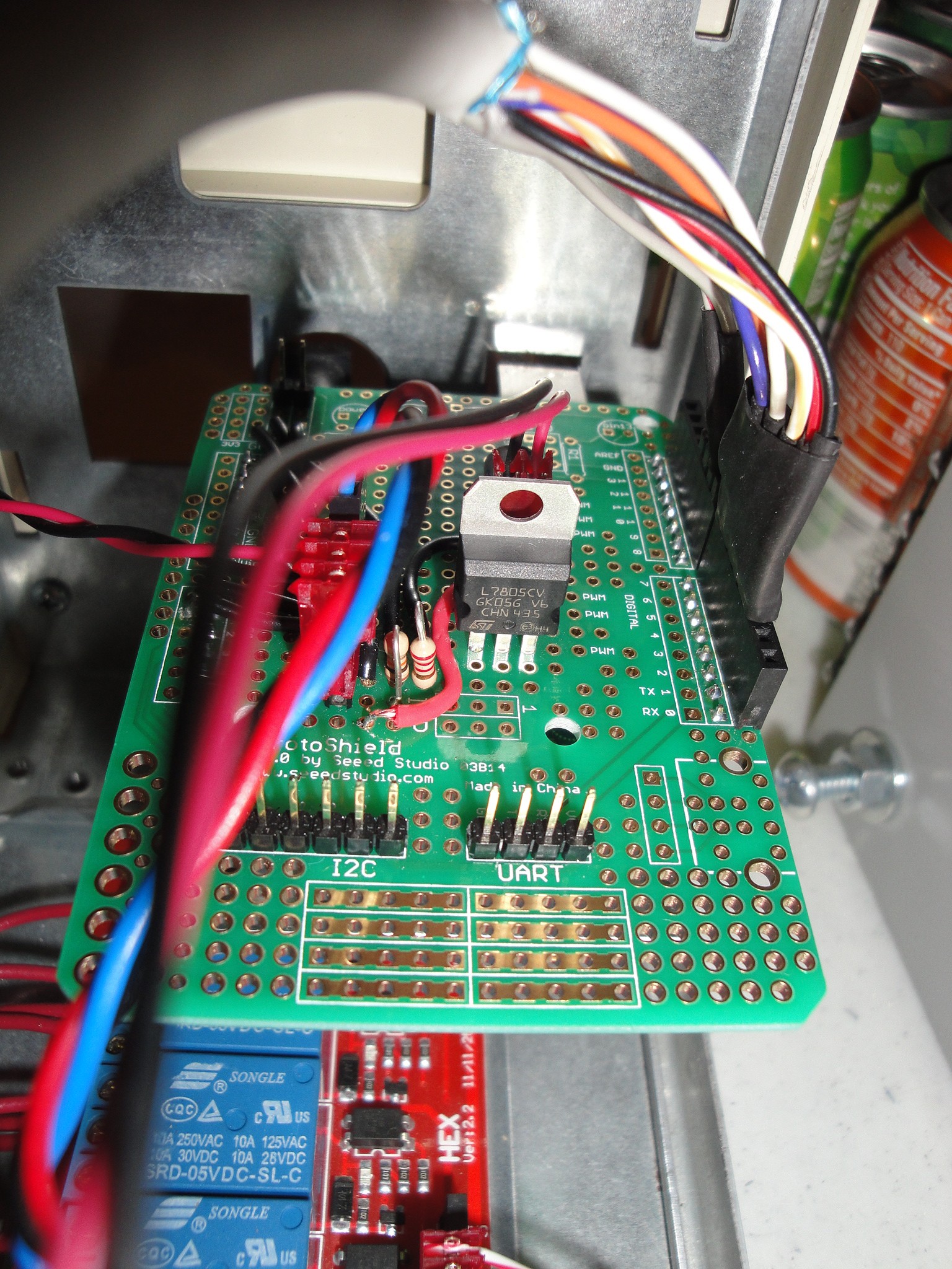
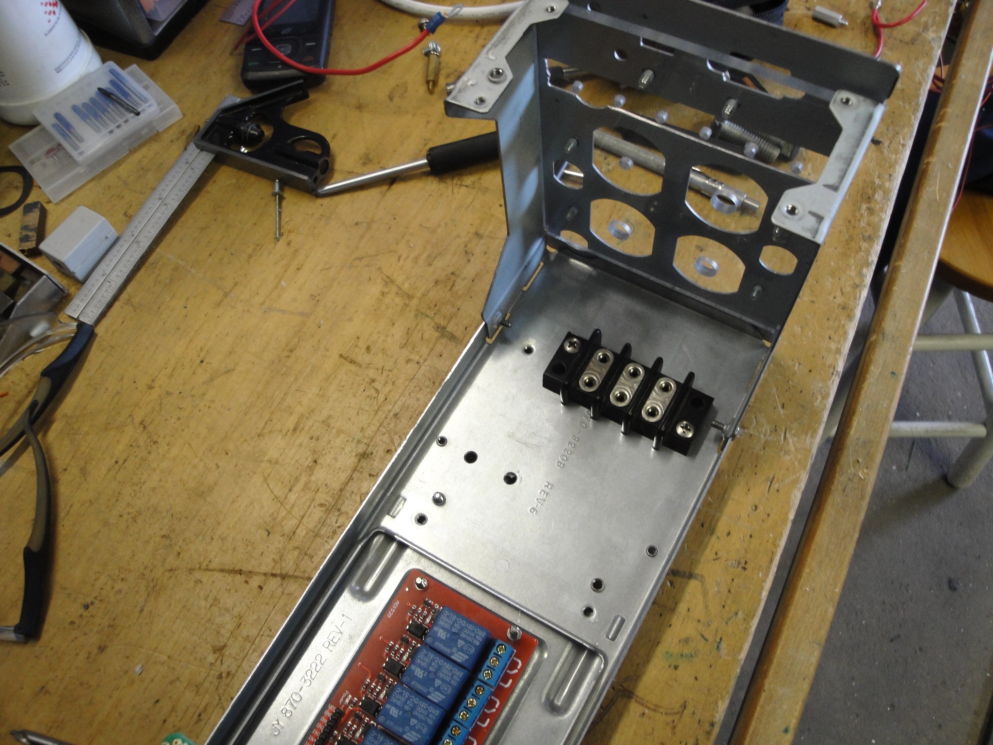
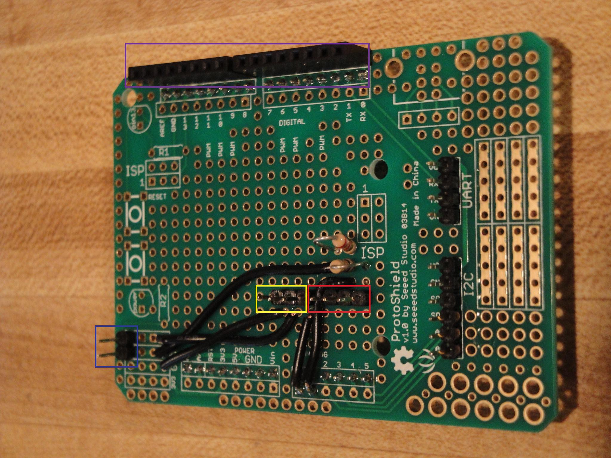
To sense the voltage of the battery, a simple voltage divider is used. The values used are 2k and 10k ohms. The 2k was connected to 12V ground which was also tied to the Arduino ground. Selecting a lower ohm value for the bottom resistor allows for the voltage divider to sense up to 27V. The first picture above shows the Seeed Studios board with the two resistors to the left.
To sense the current a DFRobot 50 Amp Current Sensor was used. This can measure +/-50 Amps DC. It outputs an analog signal whose spec can be found here:
http://www.robotshop.com/en/dfrobot-50a-current-sensor-ac-dc.html
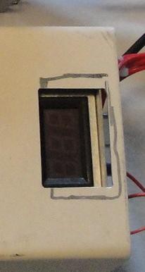
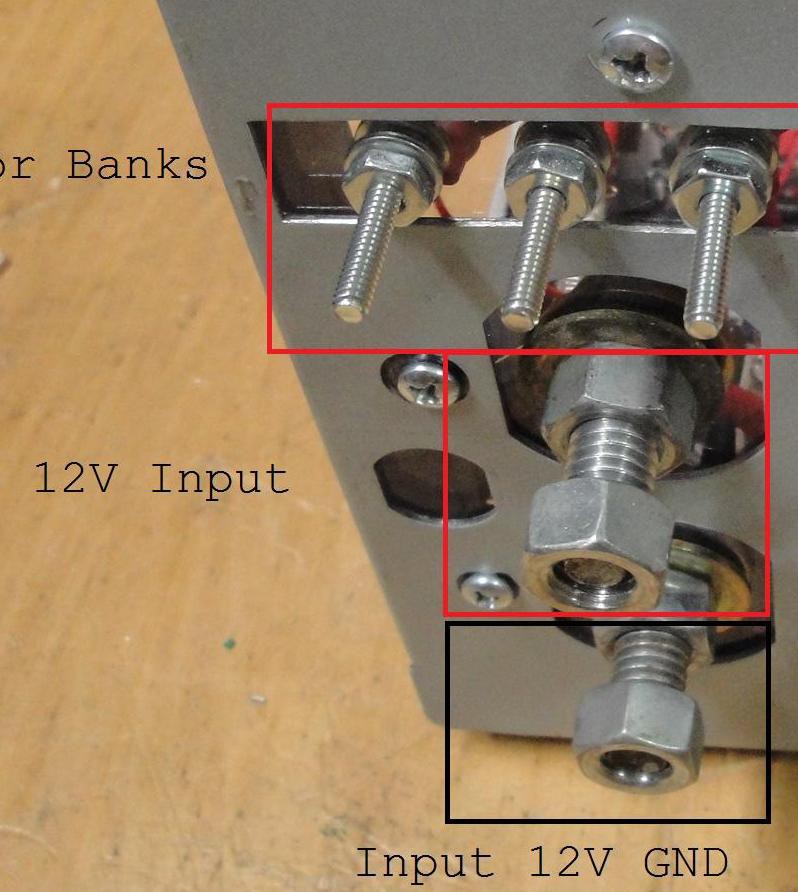
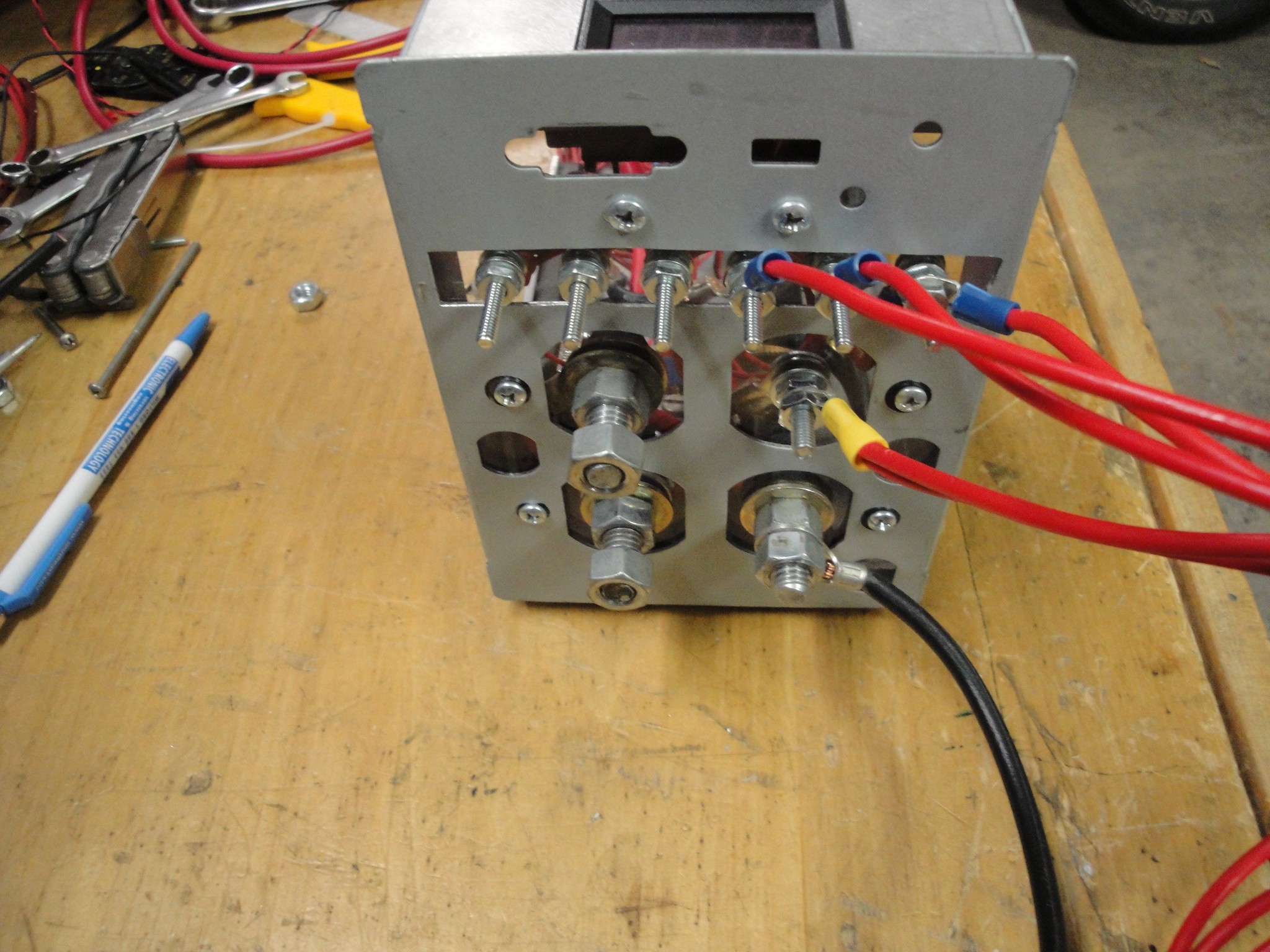
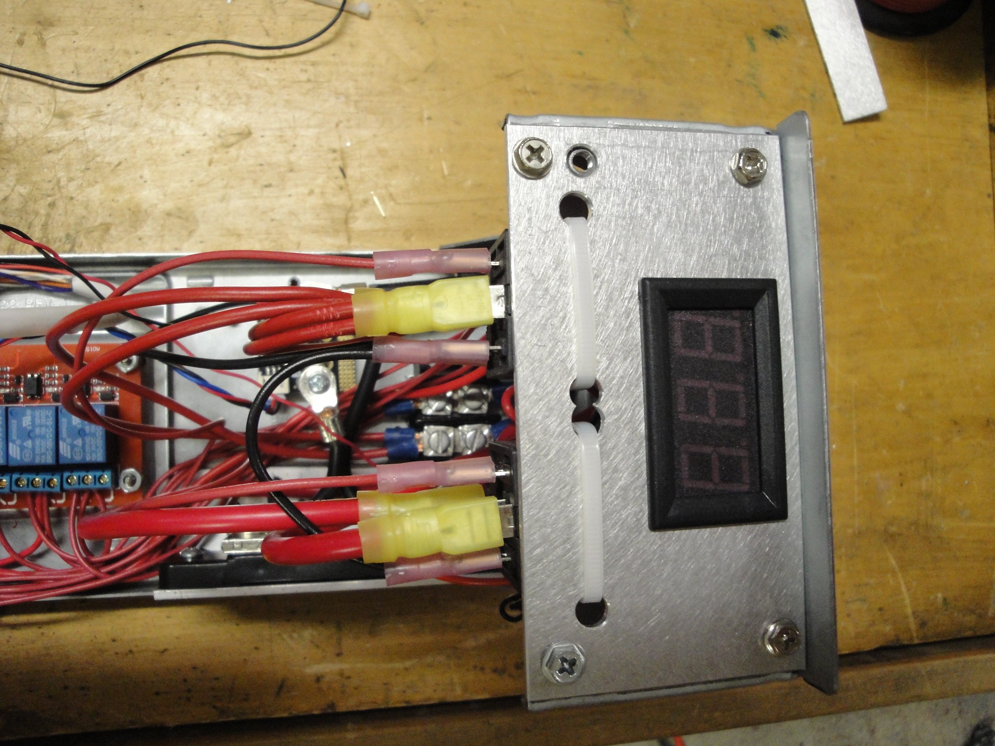
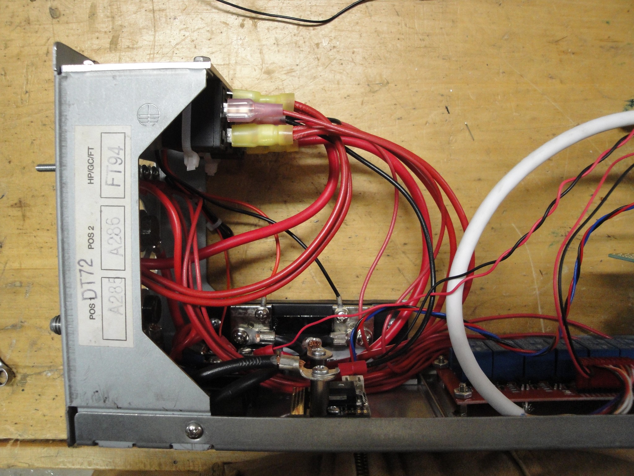
To be used as a verification, a shunt ammeter with a display was used. This is located on the back of the controller.
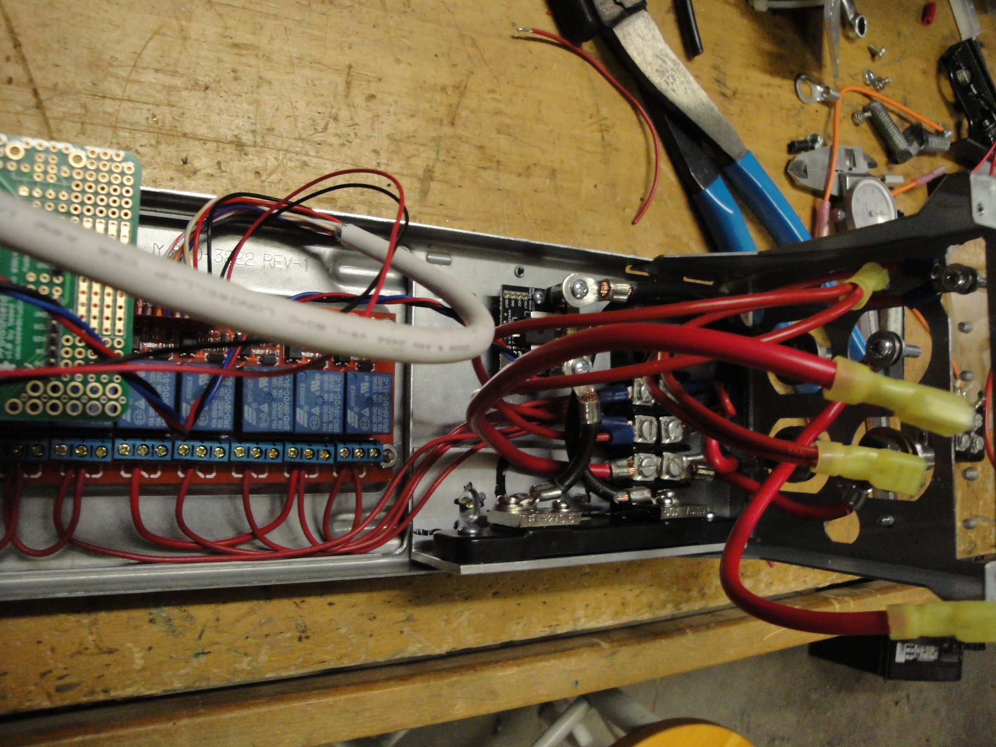
Since the Arduino cannot control 40 amps directly, some reays were used to control those loads. An 8 channel 5V control relay board was found on ebay. This allows for controlling of 10A/channel.
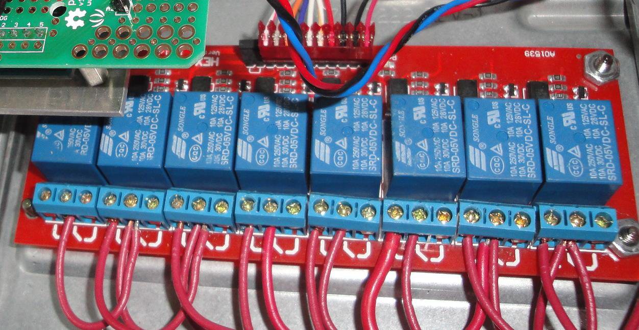
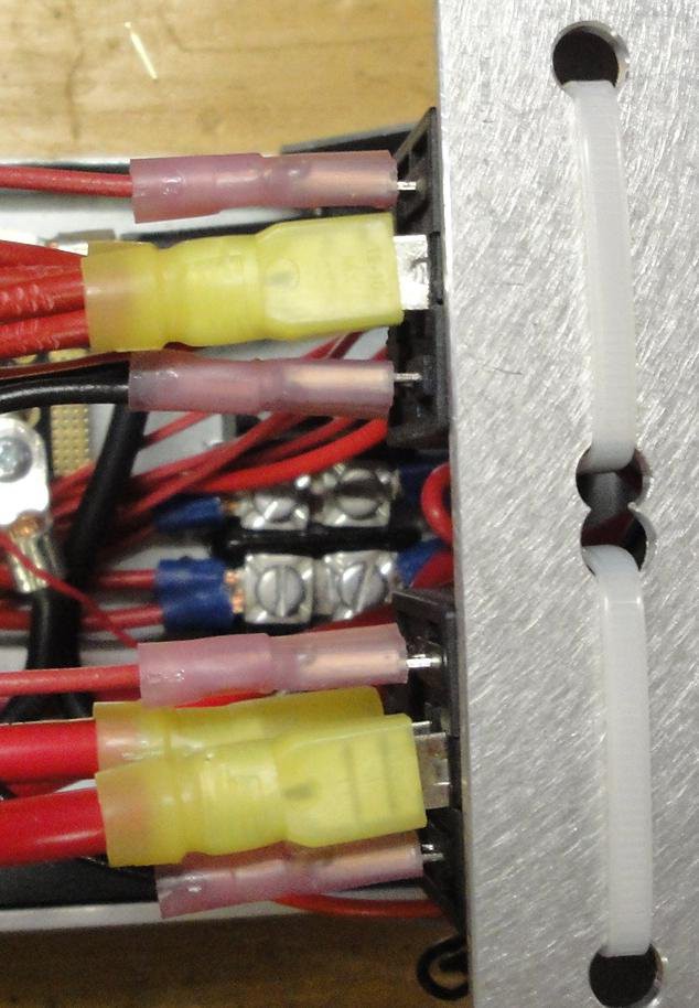
Unfortunately, the loads on bank 1 and 2 are above 10 A, so a couple of 40 A relays were used. These were purchased from an Automotive parts store.
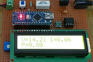
To log the data that the Arduino pumps out of its USB port, a simple logging program was created.
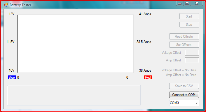
This displays the data on a graph and also shows the last known data from the Arduino below. There is a protocol setup and is as follows:
Program Status, Time (mS) of data, Voltage (divide by 100), Current (divide by 10), Resistor Bank Status, Arduino Voltage
The resistor bank status is currently not used. It was to show what banks are are on/off. After the test is complete, the student can save the data that has been accumulated to a csv file. From there it can be imported/manipulated in excel.
Running a Test:
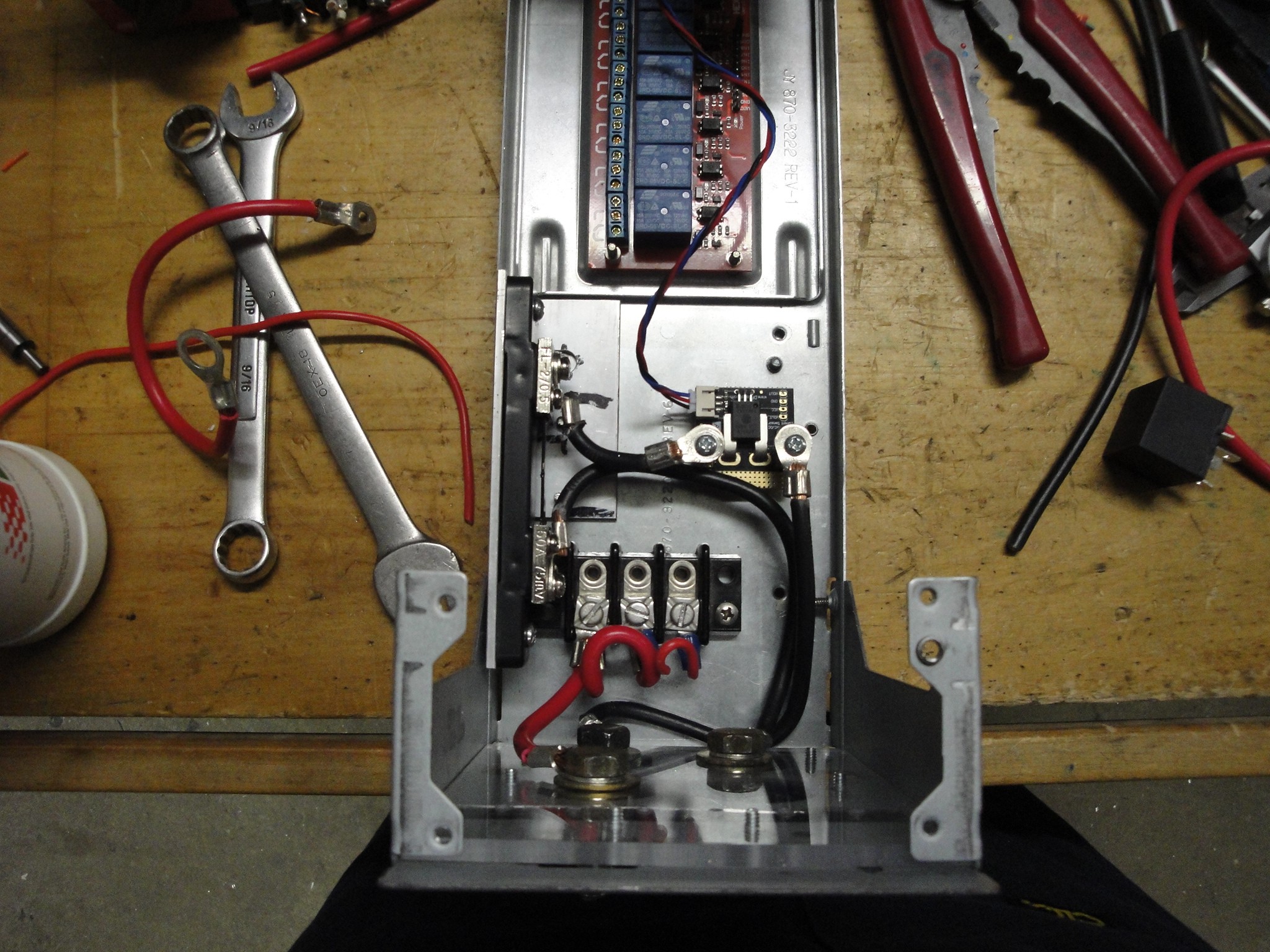
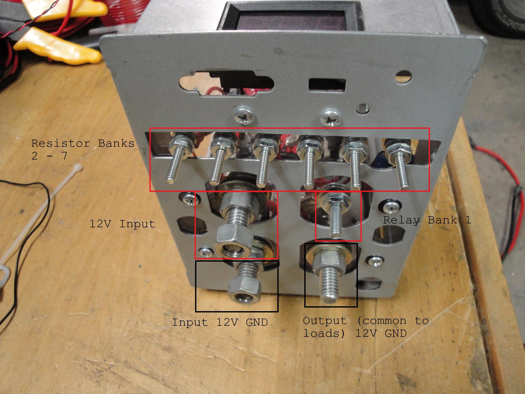
To start, first connect the battery to the lugs on the back of the controller box:
Once connected (along with the loads connected), connect the Arduino to the computer. Startup the Battery Tester program and locate the com port associated with the Arduino. This can be found by looking the device manager and locating "Arduino UNO". In the screen...
Read more »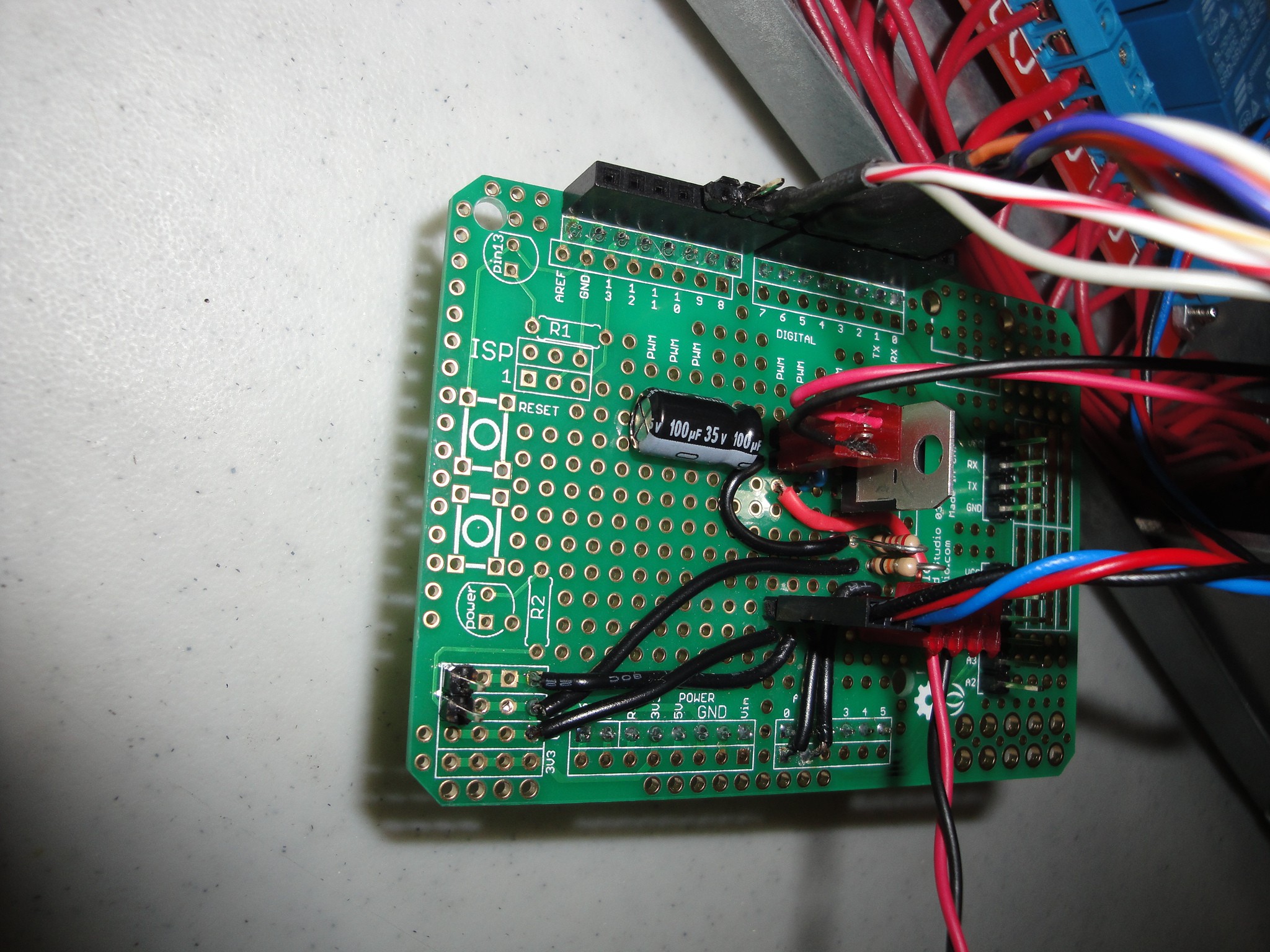
 kevarek
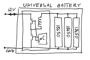
 hIOTron
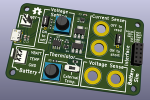
 James Fowkes