-
Code update
05/02/2015 at 06:46 • 4 commentsI've updated the code in the soldering station files. There's new content and an attempt to fix a problem with the PID controlling the temperature around 10C above the setpoint.
Other features:
- Auto turn-off with default time set to 45 minutes;
- If you reburn the frimware, it will use the Kp, Ki and Kd defined in the code instead of trying to load them from EEPROM, unless you run the autotune. This makes it possible to use the soldering station without autotuning.
That's it.
-
Revising the amplifier
04/02/2015 at 10:06 • 0 commentsI've noticed that the temperature sensor amplification could be improved.
Just follow these instructions:
- R3 of 10kohm
- R4 of 47kohm
- R5 of 1kohm
If you want an explanation, keep reading.
The equation for the op. amp. output voltage is given by:
The ideal value for Vo is just below 5V when Rsens is at it's greatest value. Assuming Rsens of 200ohm when hot, calculating for 48x gain and R3 of 10kohm:
That means the max value at the output of the operational amplifier is 4.71V. We could increase this value and that would increase the precision in the temperature readings.
-
3D printed case and finishing it off
02/17/2015 at 17:26 • 0 commentsThe last project log guys, sorry for the delay.
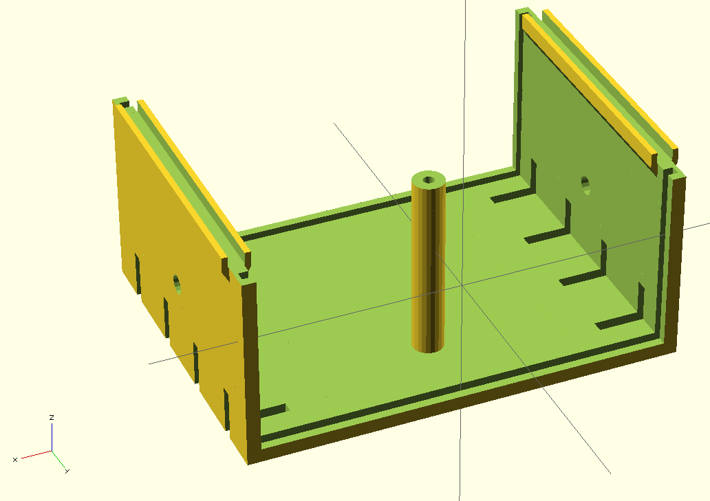
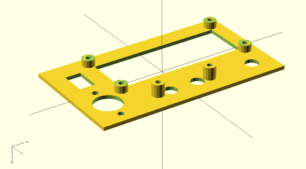
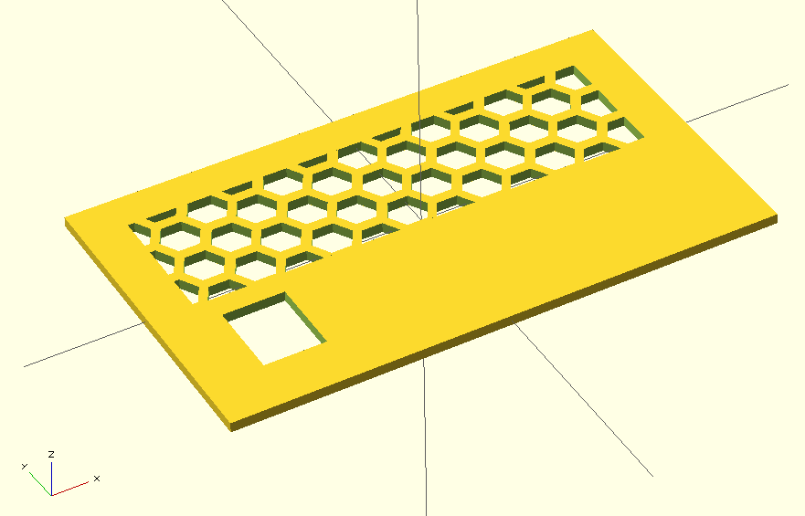
I've modeled a case and 3D printed it to house the electronics. The case was modeled in OpenSCAD.
Bottom:
![]()
Top:
![]()
Front:
![]()
Back:
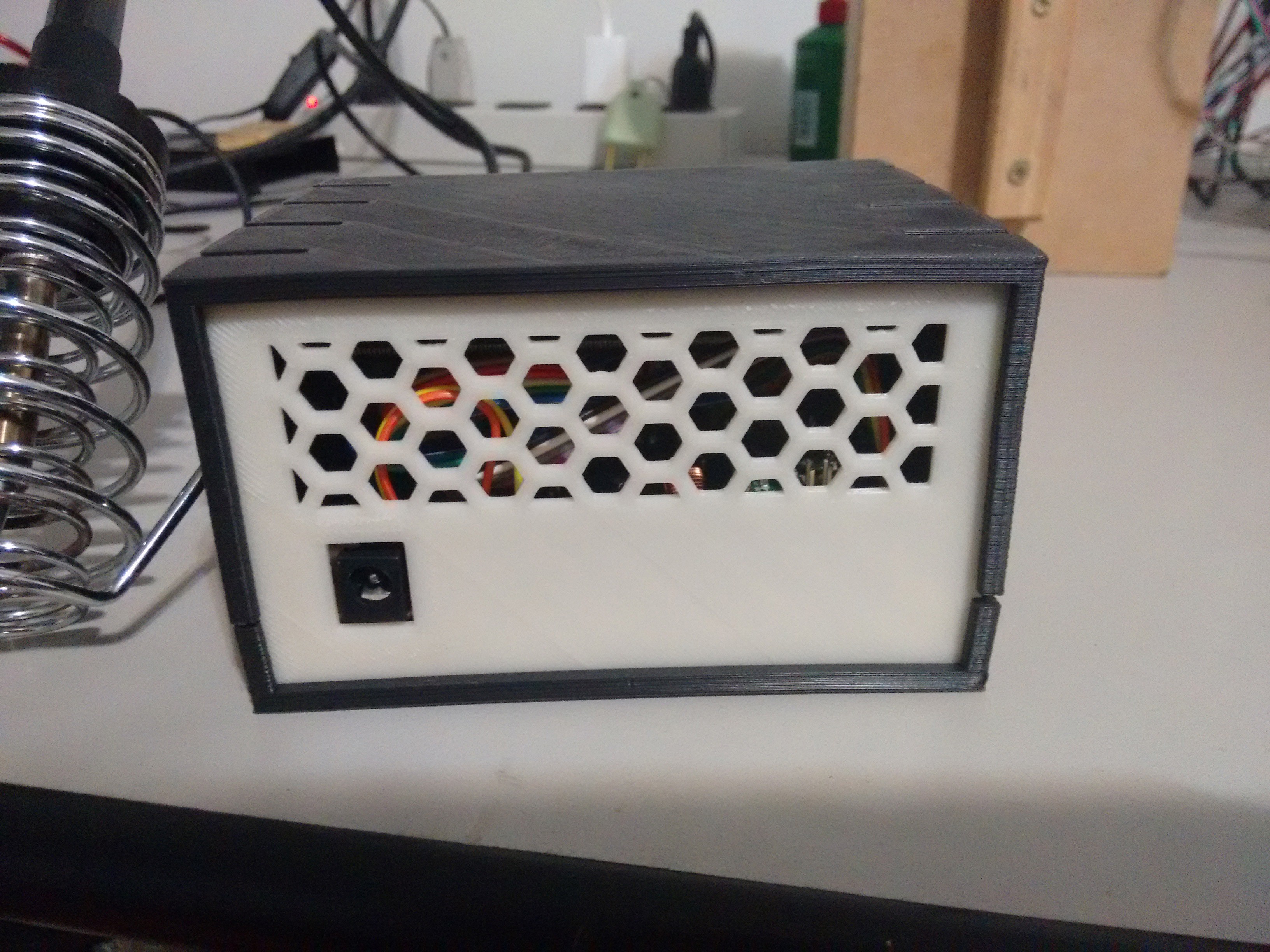
![]()
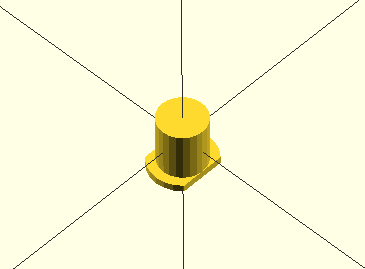
Button caps, for the tactile switches:
![]()
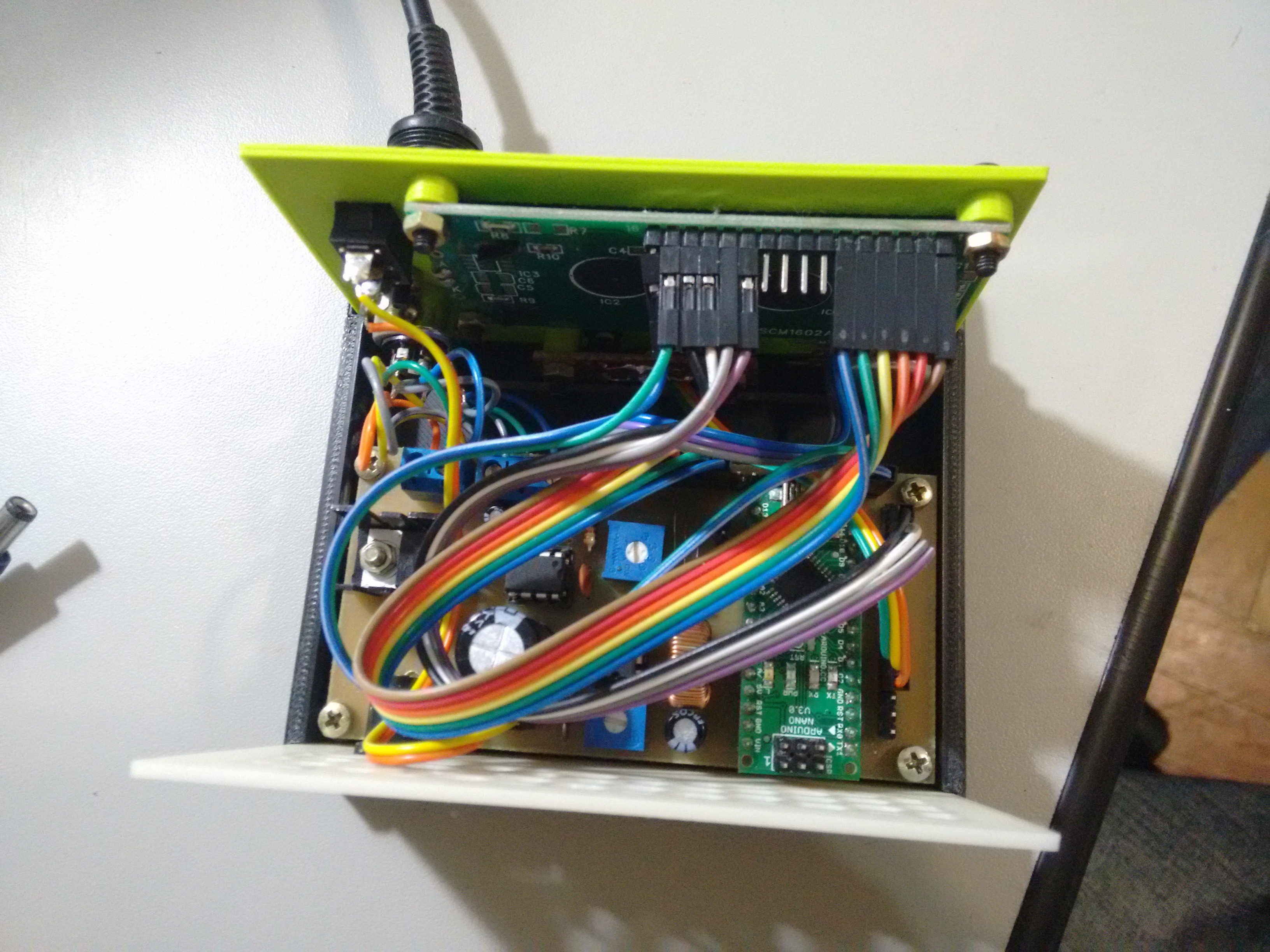
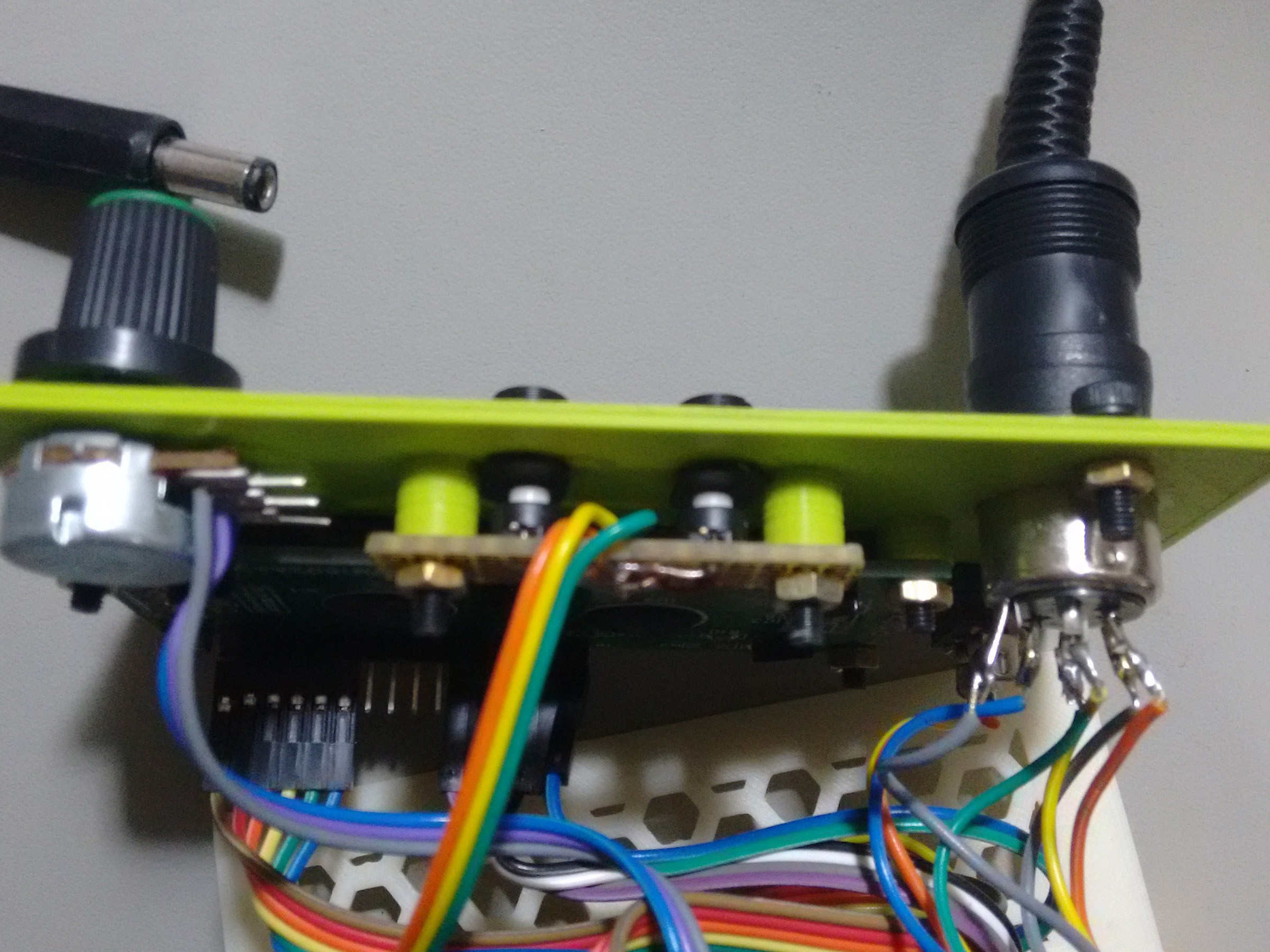
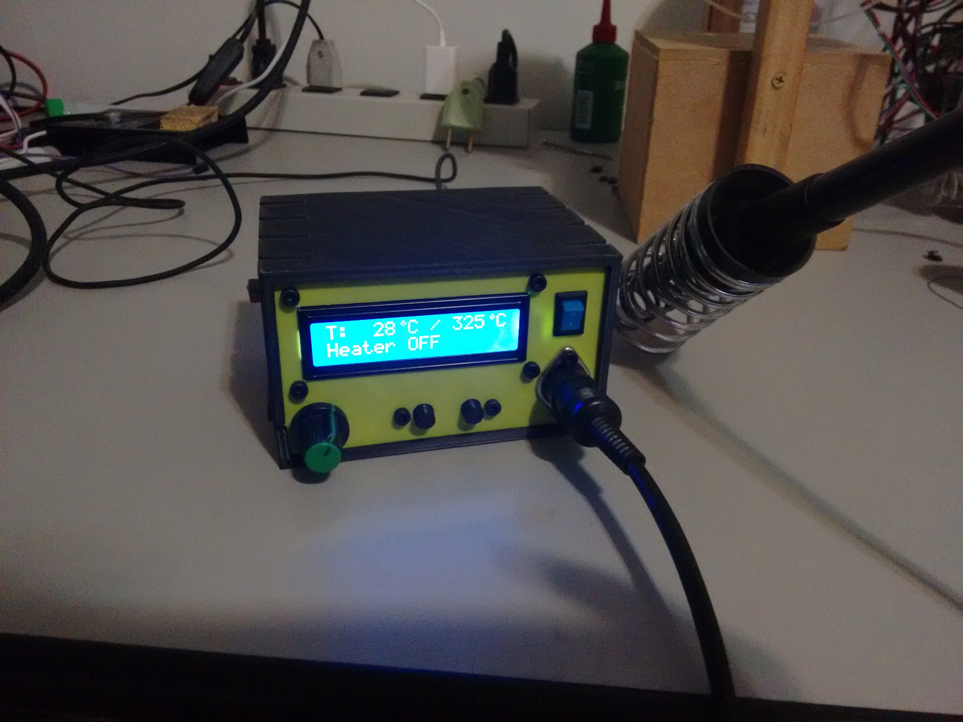
With everything printed, I went to assembly. It became a real mess of wires. One thing to note is that the center cylinder with the bolt hole was too close to the LCD pins.
![]()
![]()
![]()
![]()
I drilled a 5mm hole on both sides of the top part and fitted a M5 threaded rod to fix the rest for the iron.
That's about it. All files are now available. If anyone feels like improving the project, please do it.
Thanks for the ones who followed the (slow) progress of this project and I hope it can be of some use to someone out there.
Files are in the projects main page.
-
Software!
01/10/2015 at 07:21 • 0 commentsIt's been a long time since the last update, sorry guys. I've got rather busy, then came end year and I went to visit my family, without any contact with the project.
Anyway, I was able to finish the project just before leaving, but had no time to post about it. In this post I'll talk about the software development and I'll try to finish the project as soon as possible.
There were some problems, mainly with the PCB, as I noticed later. I didn't feel the problems were big enough to make me redo the PCB, so I'll just leave it as it is right now.
The first problem was related to the LCD data bus. I didn't know that A6 and A7 pins on Arduino Nano were input only, and these two pins were used as D6 and D7 data lines to the LCD. This was fixed rather easily by using other available pins on the side of the board. I didn't even swap that vertical pin header to a right angle one after discovering that.
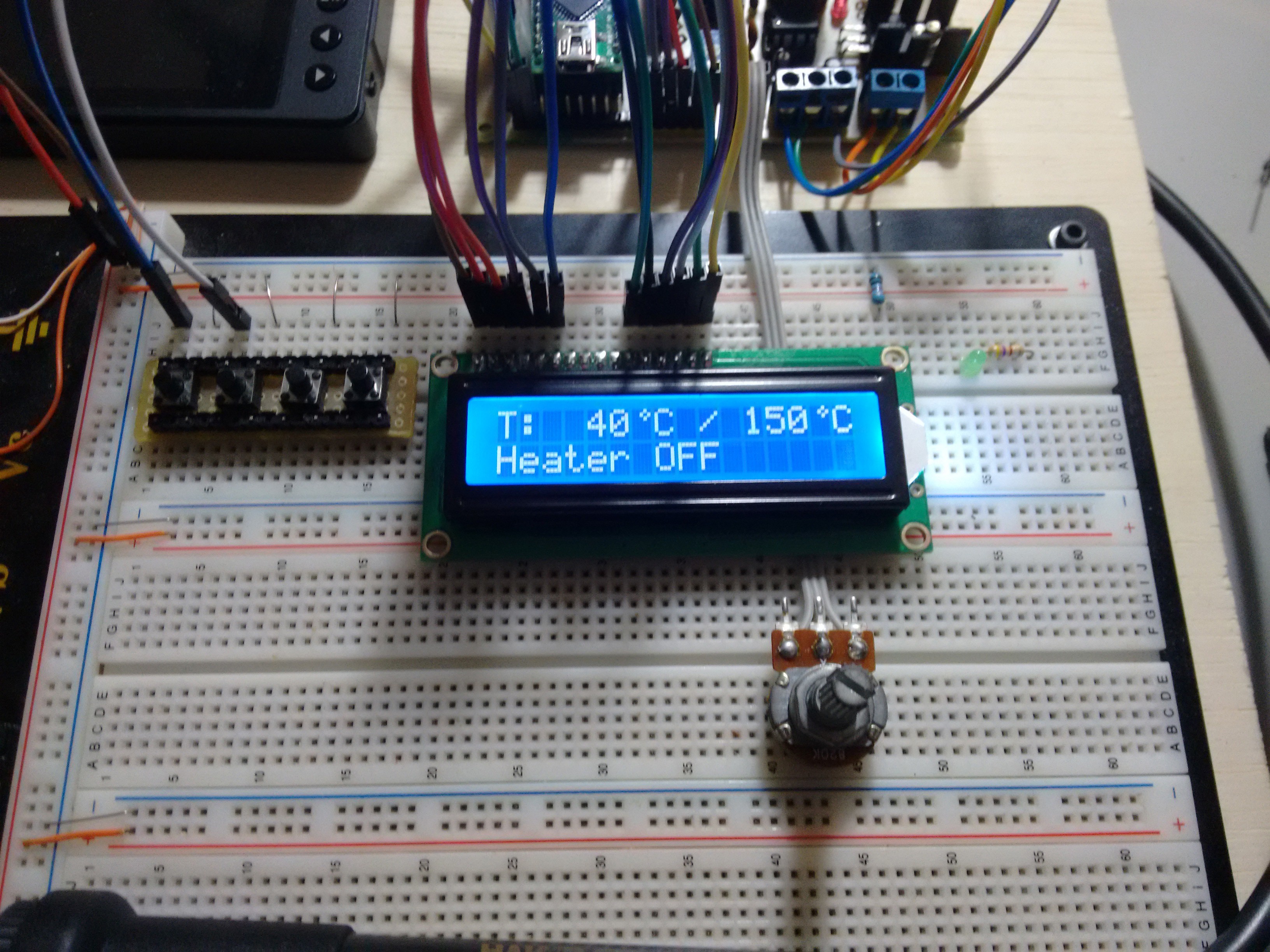
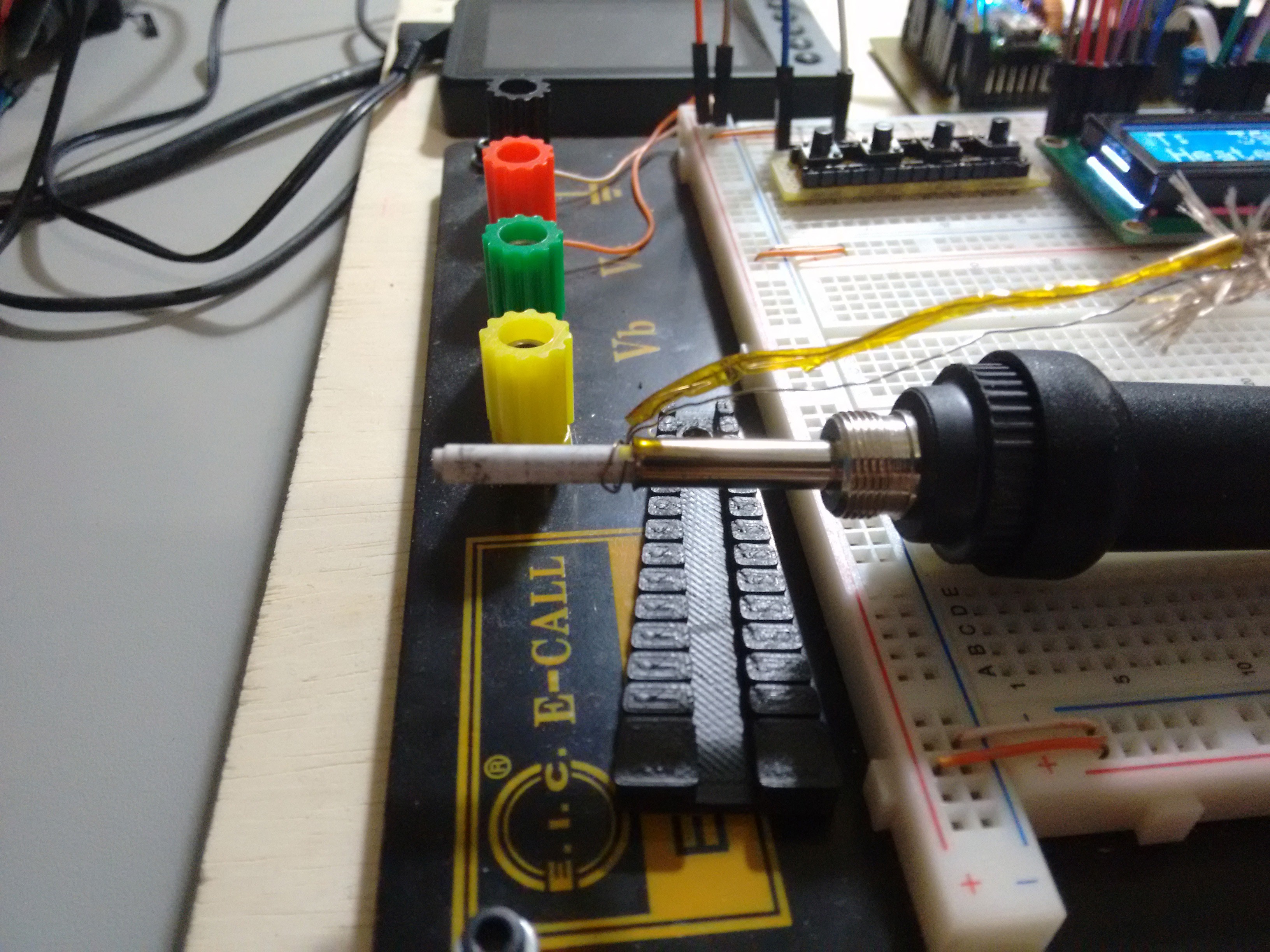
Now, I had to do the software. I prepared a breadboard with the LCD, some tactile switches and a potentiometer. I also connected the soldering iron and attached a thermocouple to the heating element.
![]()
As I had noticed before that the PTC resistance was almost linear over a wide temperature range, I chose to use a linear function to calculate the temperature. I measured two different temperatures and the corresponding analog value to calculate the equation.
In the code you can uncomment the following lines to show the analog value read by the Arduino:
lcd.setCursor(13, 1);
uint16_t temp_analog = 0;
temp_analog += analogRead(TEMP_PIN);
temp_analog += analogRead(TEMP_PIN);
temp_analog += analogRead(TEMP_PIN);
lcd.print(temp_analog/3);
I got the analog values with the iron at 30C and 450C, as measured in the thermocouple. These values were 228 and 590 respectively.
The equation will look like:
where Y is the temperature and X is the analog value read from the sensor. You will need the two analog values and the two temperatures to calculate "a" and "b".
To find "a", subtract your higher value temperature from your lower value temperature and divide by the subtraction of their correspondent analog values. Using the values I got: (30C, 228) and (450C, 590) where 30C is 30 degree Celsius and 228 is the analog value.
Now, to find "b" use the the linear equation with "Y" as one of the values you found and X is it's analog value. The value of "a" is the one found just before. Using (30C, 228):The values of "a" and "b" should then be set in the firmware:
#define EQUATION_A    1.16
#define EQUATION_B    -234.48
Next in the code, I used PID to control the heating element and the code has a PID autotune that should be ran when turning the soldering station for the first time.
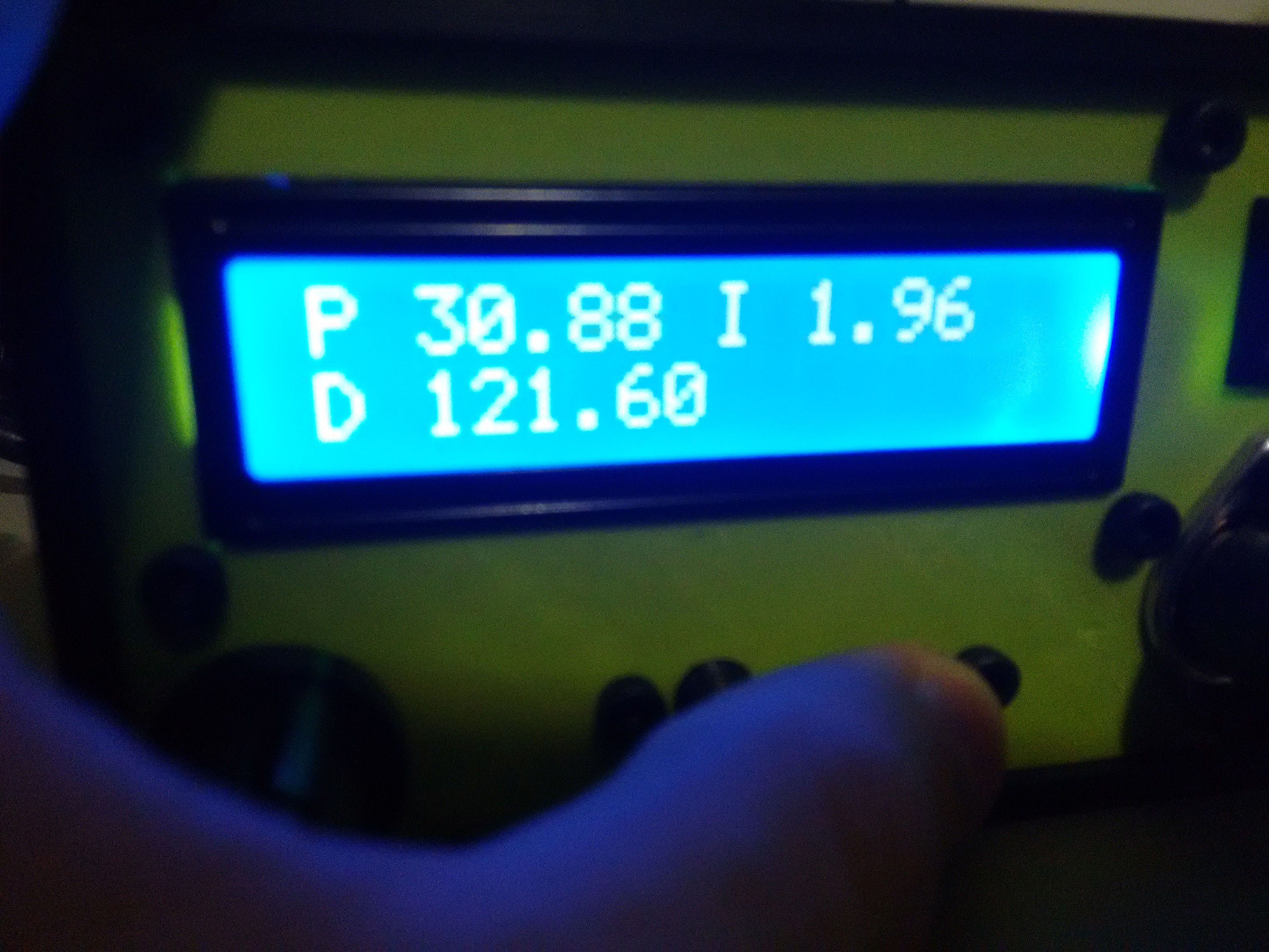
To run the autotune, hold the autotune button and turn on the soldering station. The autotune will then save the values to the EEPROM and these will be loaded every time you use the soldering station. The values can be checked by pressing the autotune button while the soldering station is on.
![]()
The only thing I think is still lacking is an auto turn off function.
To finish this post, have some more pictures of the development setup:
![]()
![]()
![]()
The code is available here.
-
Board assembly
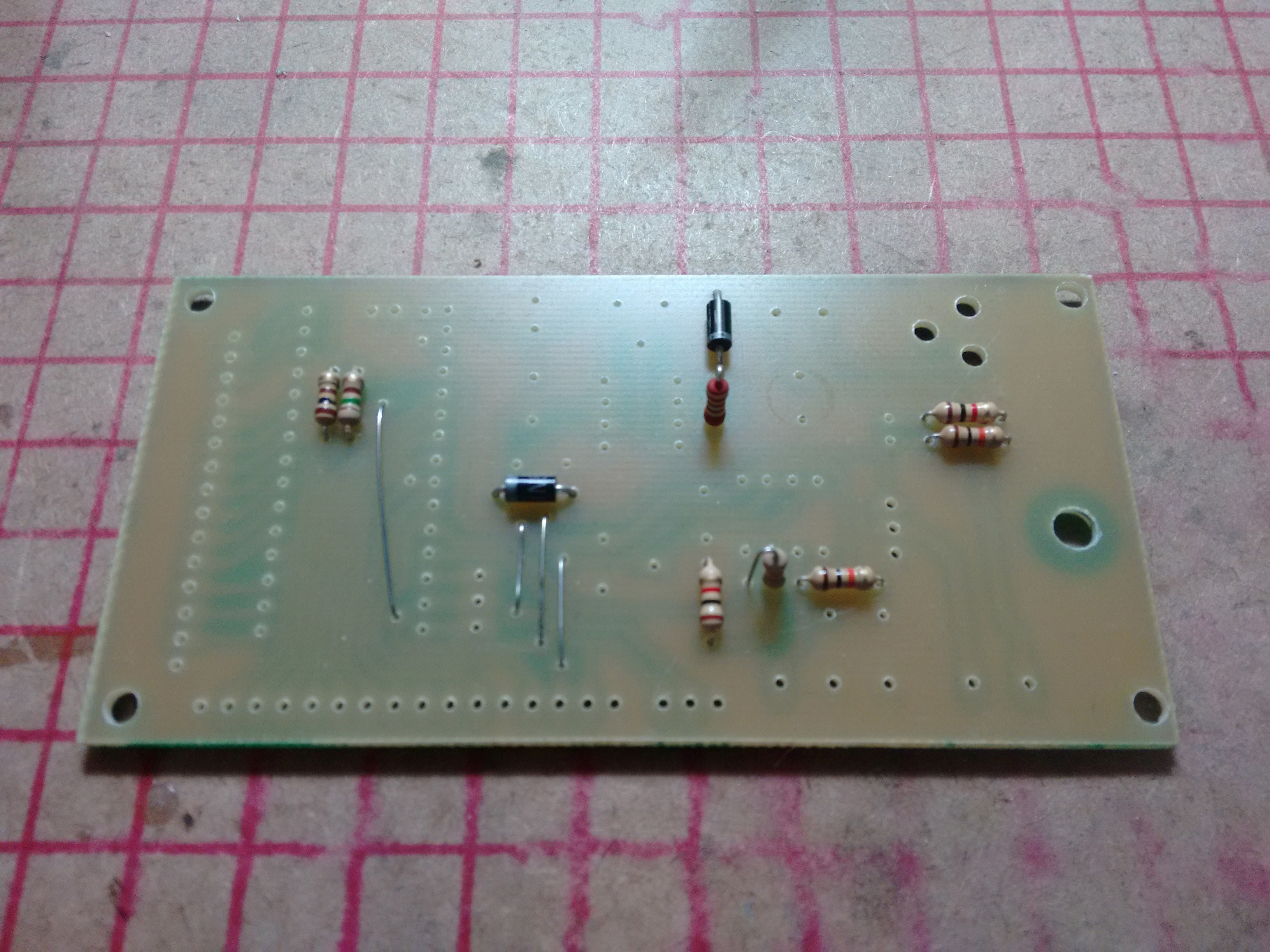
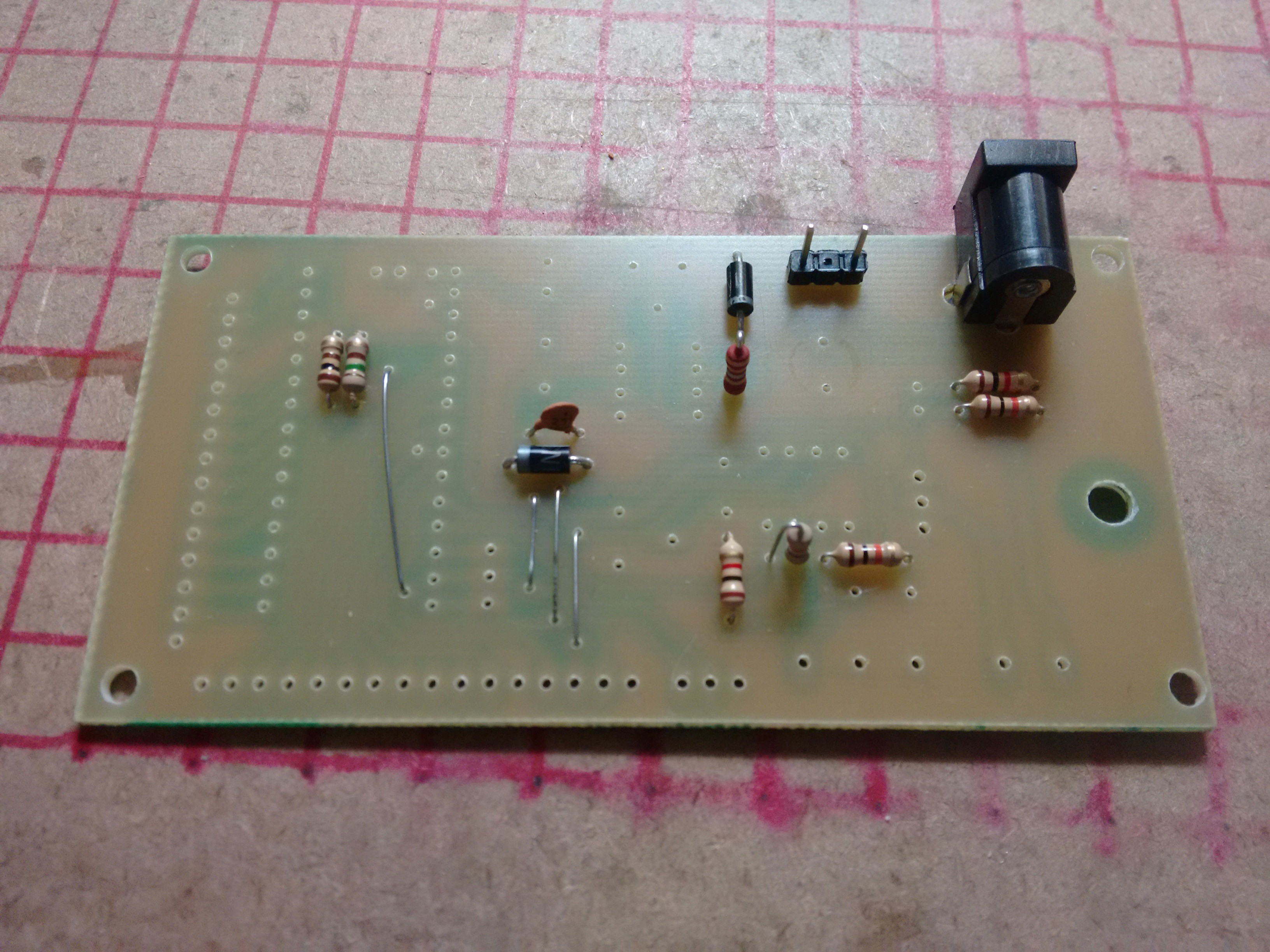
11/29/2014 at 04:01 • 0 commentsI started the assembly with the jumpers, resistors and diodes first:
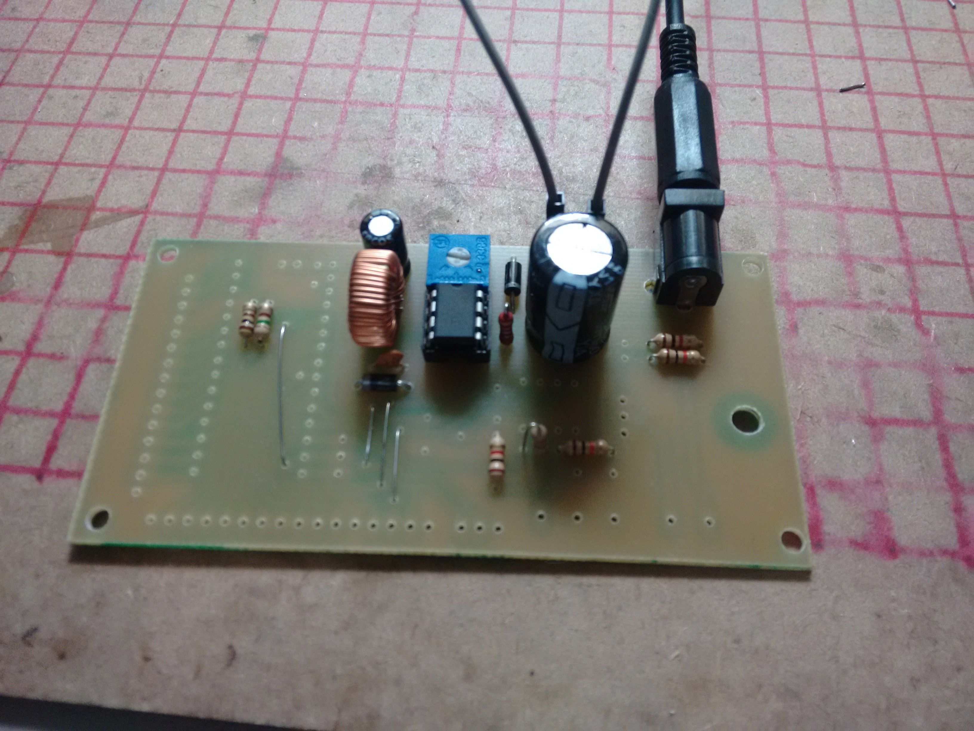
![]() Then, I went to finish the switching power supply. Power jack, power switch connections and capacitor.
Then, I went to finish the switching power supply. Power jack, power switch connections and capacitor.![]()
Notice that I soldered pins instead of the screw terminal to the power switch. Didn't want any wires going through the back of the board.
Continuing with the power supply, I soldered the rest of the components necessary, and tested it.
![]() Everything working alright. I set the output voltage to 12V with the potentiometer. You want to set the output voltage now, because if you connect your Arduino without setting the voltage first, you could fry it.
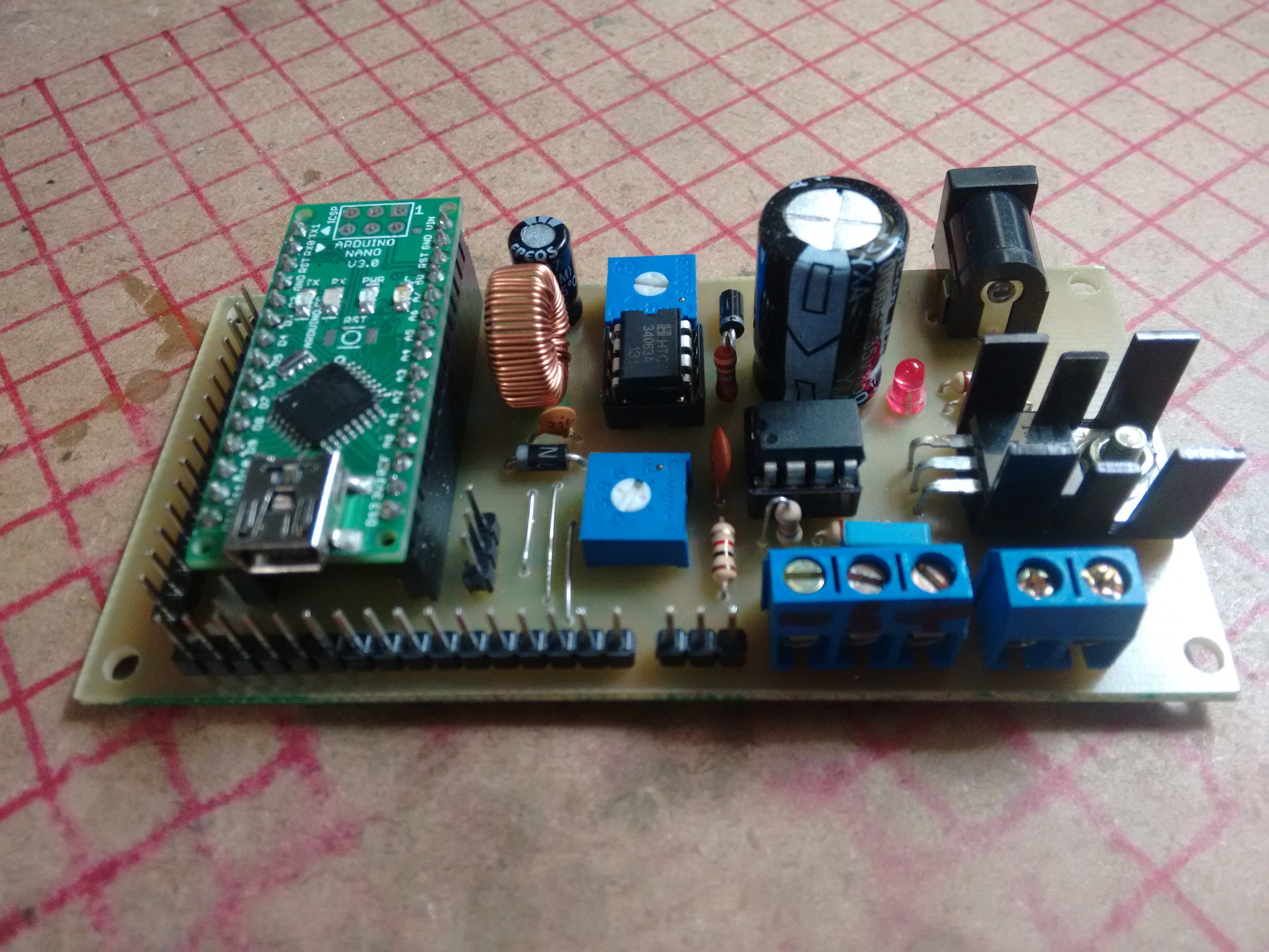
Everything working alright. I set the output voltage to 12V with the potentiometer. You want to set the output voltage now, because if you connect your Arduino without setting the voltage first, you could fry it.With the power supply working, I soldered the rest of the parts.
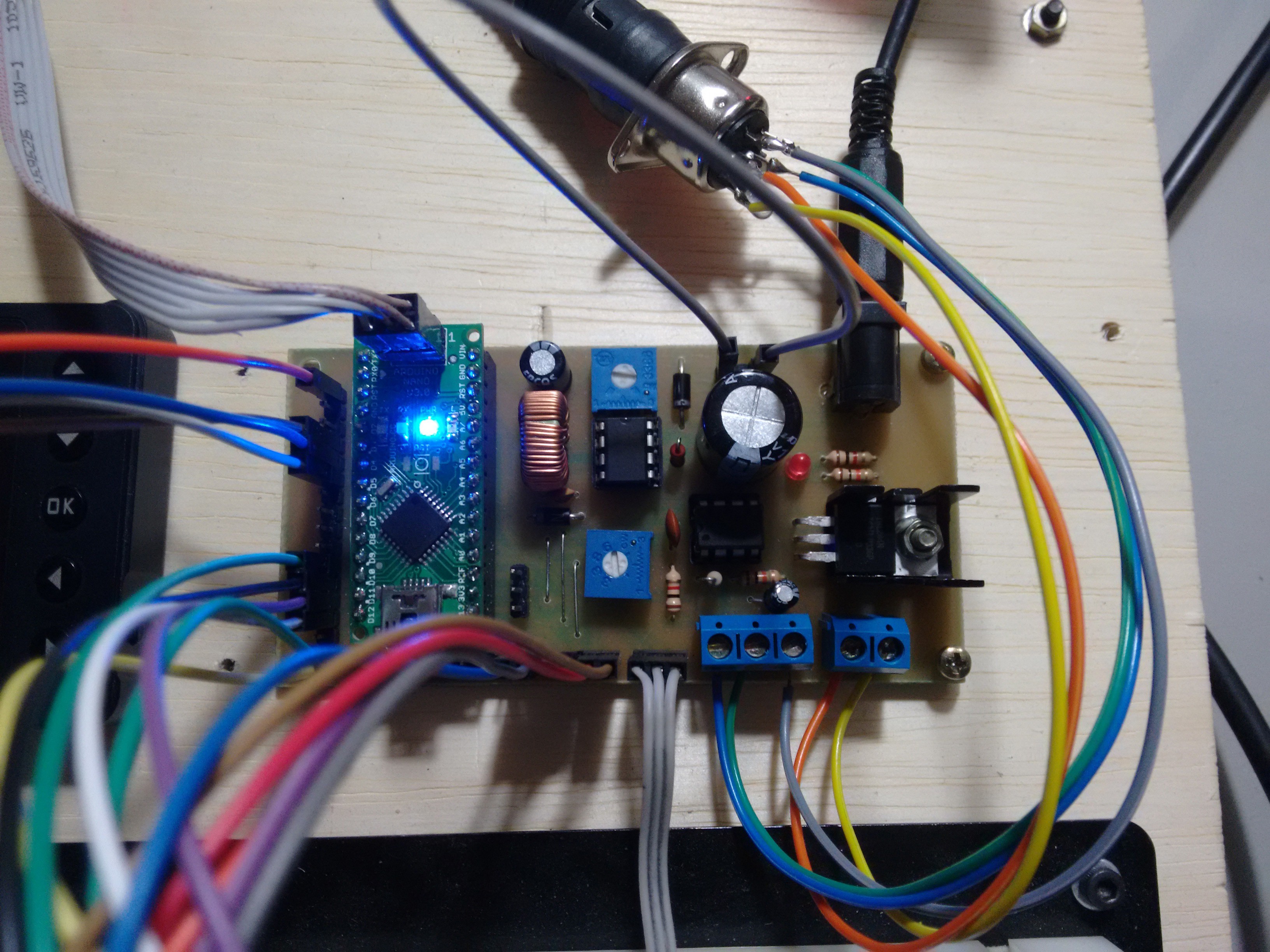
![]()
The USB connector is over the LCD pin header. I was going to use 90 degree pin headers, but I had none right now. I'll swap the pin header later.
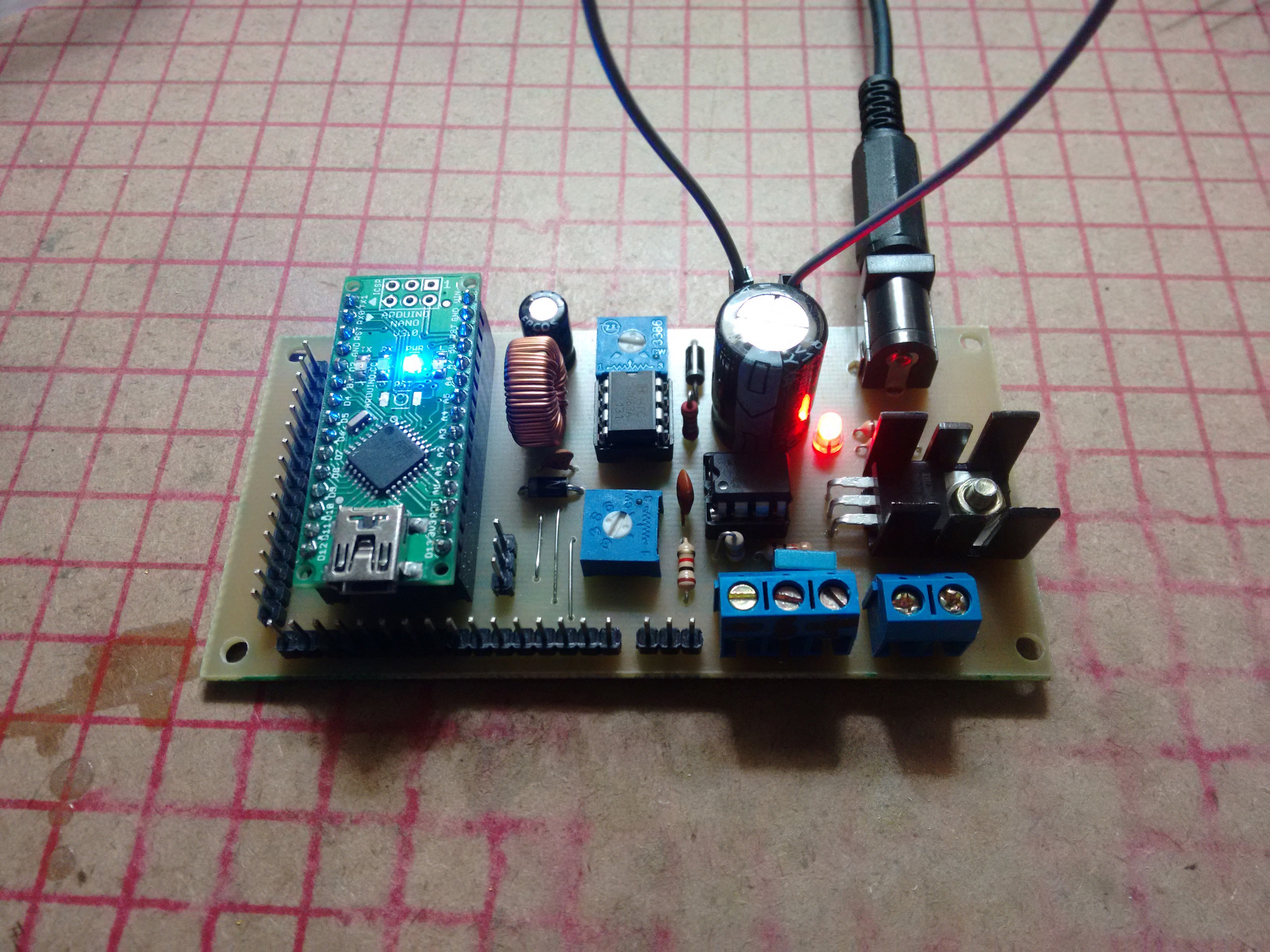
With the power on:
![]() Everything seems to be working as expected. Next thing now is the program, but I'm rather tired after soldering the board.
Everything seems to be working as expected. Next thing now is the program, but I'm rather tired after soldering the board.I'll do it next time.
-
Board etched
11/29/2014 at 01:07 • 0 commentsWent to college today and the projects room heat press was dead. Asked a professor and he let me use the heat press on his lab.
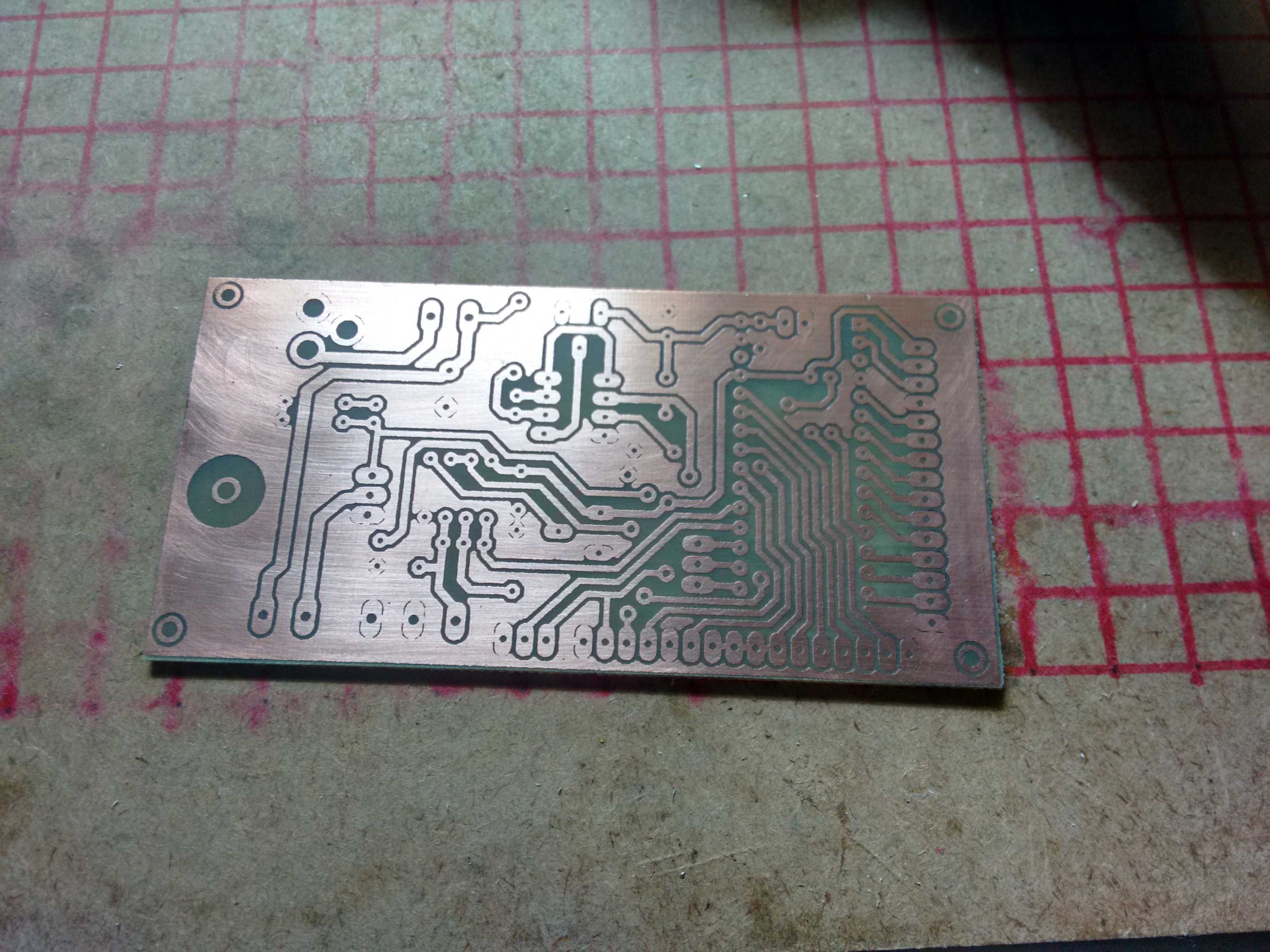
Transferred the toner and etched it at college:
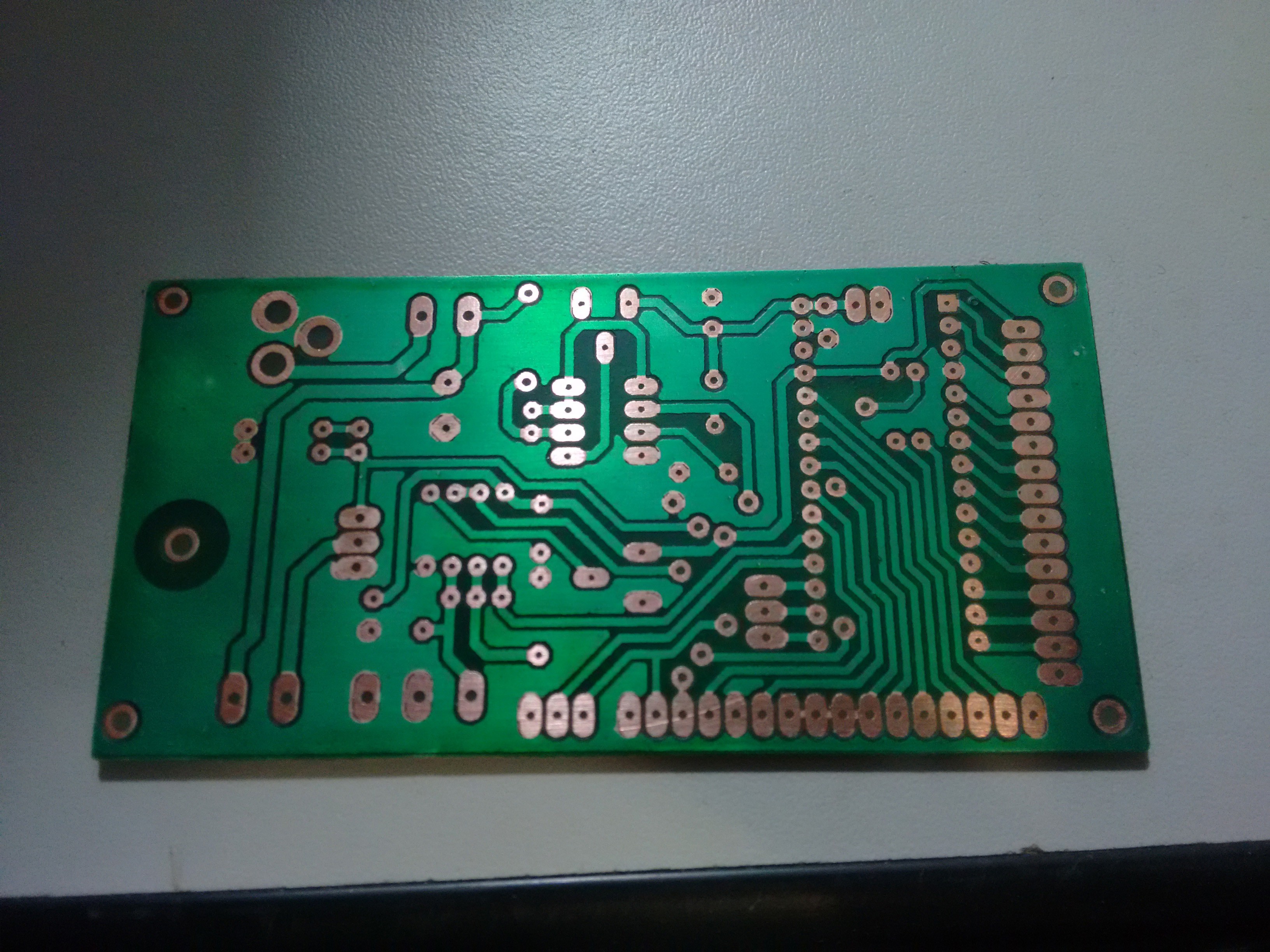
![]() At home, I applied kind of a solder mask. It's actually a UV paint for purposes other than protecting PCBs.
At home, I applied kind of a solder mask. It's actually a UV paint for purposes other than protecting PCBs.![]() I have already drilled it, and will start assembling it soon.
I have already drilled it, and will start assembling it soon. -
Schematics, board and resistance table
11/27/2014 at 18:16 • 6 commentsMade some tests during the week on a breadboard. Tested PWM on a MOSFET, the LCD, made a table with the PTC resistance in the 30C ~ 450C range, etc.
After I decided how to build the hardware, went to Eagle and created the schematics and board.
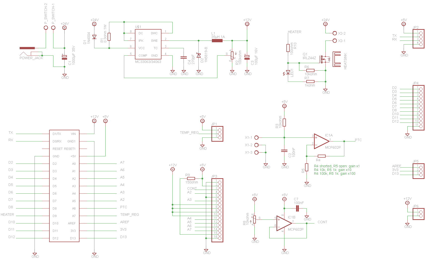
The chosen MCU is an Arduino Nano, and the operational amplifier a MCP6002, cause I have some laying around. Any op. amp. that works with 5V power supply, is rail-to-rail, and have the same pinout should work.
Schematics:
![]()
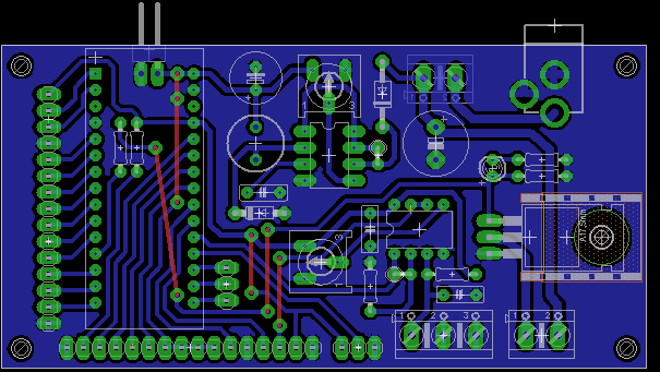
Board:
![]()
The board fits in a 5x10cm copper board. As I made it to be easily toner transferred it was rather hard to route it after all the time doing two-sided boards with 8mil tracks.
I'll probably etch one of these tomorrow at college. They have a good heat press I can use to transfer boards there.
-
Heater Resistance and Power
11/27/2014 at 13:18 • 3 commentsI've measured the heater resistance and noticed that it's smaller than the resistance for the rated Voltage/Wattage.
The measured value is around 4Ohms. As the soldering iron is rated at 24V:
P = U² / R
P = 24² / 4 = 144W
There it is. The soldering iron is rated at 24V 50W, but if you just connect a 24V supply, it will probably kill itself. You need to control the power delivered to the iron.
There's no need, then, to use a 24V power supply. The unmodified 19V notebook power supply should do the trick.
I've measured the resistance of the heater while hot, to how much it changes with temperature, but it raised to 7Ohms only at 450C.
That said, I've moved the power supply project logs to a new project, and will move a little faster on this project, as I have some other projects on my backlog.
Hakko 907 based Soldering Station
A soldering station based on the easy to source Hakko 907 soldering iron, which is a 24V 50W soldering iron with integrated thermistor.
 Kuro
Kuro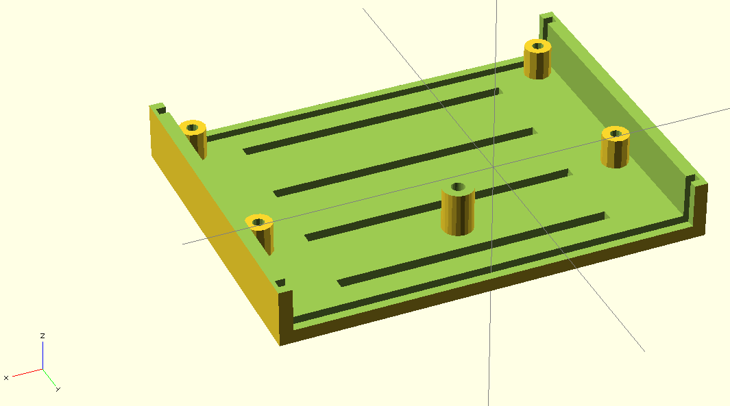

 Then, I went to finish the switching power supply. Power jack, power switch connections and capacitor.
 Everything working alright. I set the output voltage to 12V with the potentiometer. You want to set the output voltage now, because if you connect your Arduino without setting the voltage first, you could fry it.
 Everything seems to be working as expected. Next thing now is the program, but I'm rather tired after soldering the board.
 At home, I applied kind of a solder mask. It's actually a UV paint for purposes other than protecting PCBs.
 I have already drilled it, and will start assembling it soon.