-
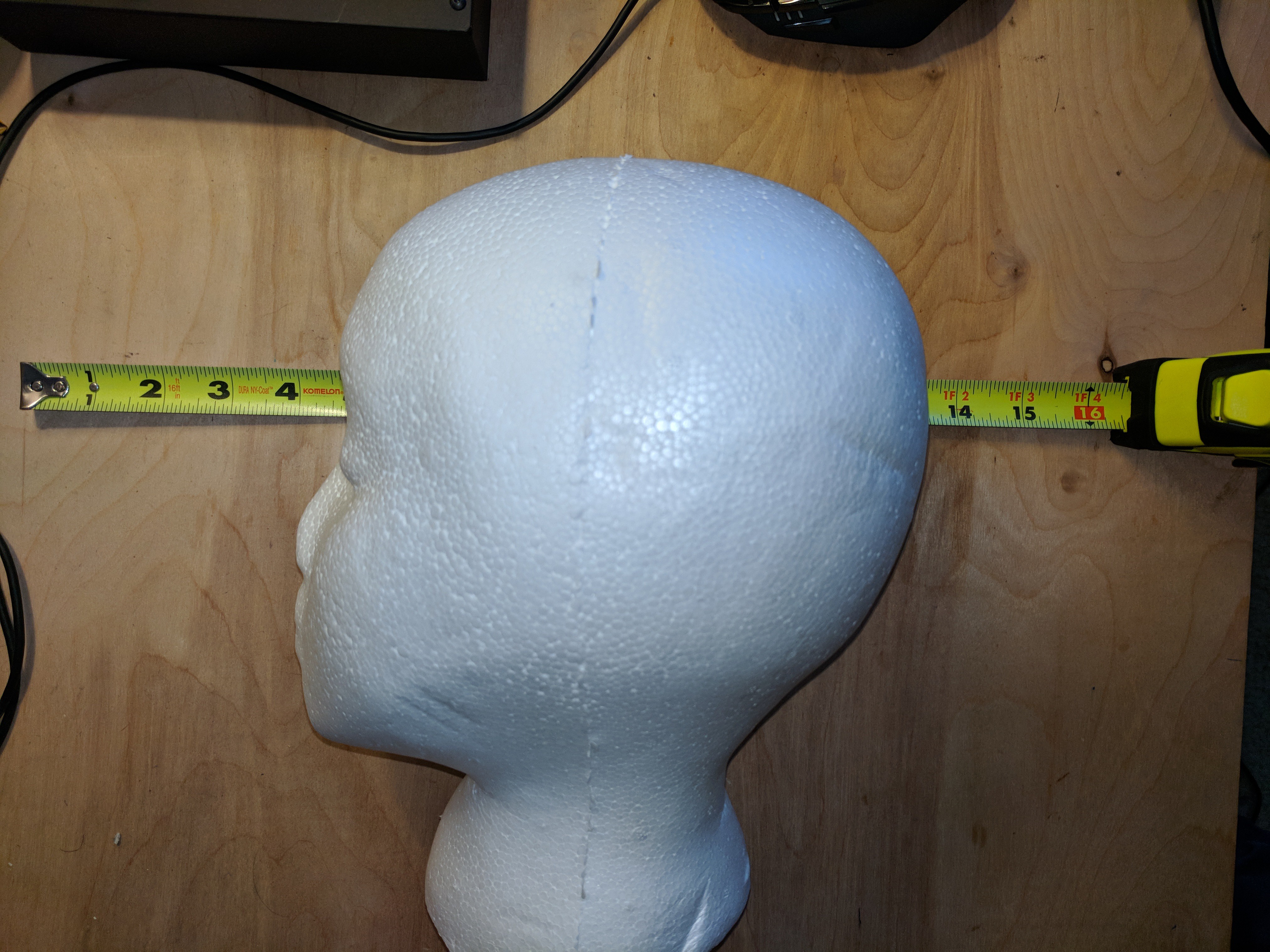
1Measure your head
Before anything can begin, you must know the rough dimensions of your noodle. That way you can find a television that will fit around your head.
Mine was a size alright.
![]()
-
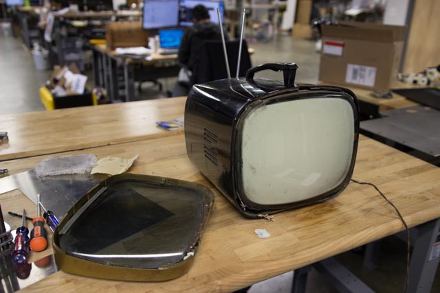
2Find your Television
I searched good ol' Ebay, Craigslist, but found mine on Etsy (surprisingly).
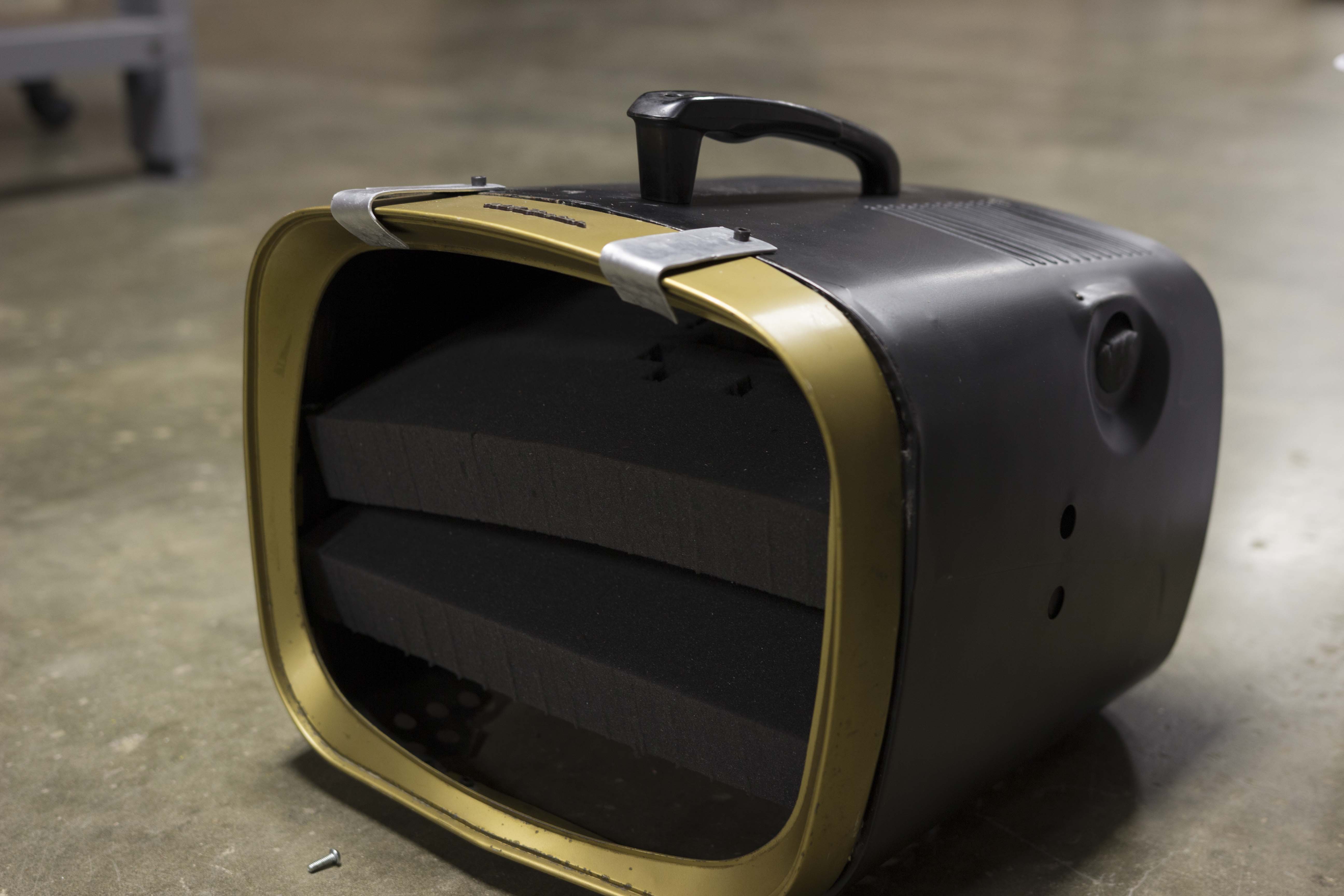
Mine measured roughly, 14 in x 10 in x 9 in so it could fit just about anyone.
![]()
-
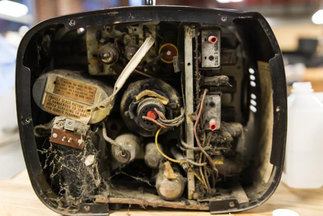
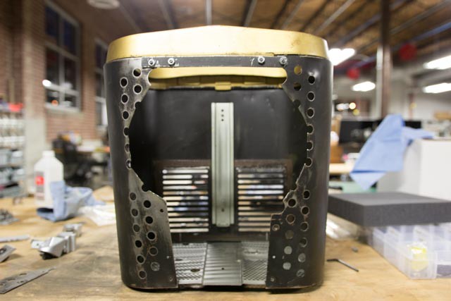
3Gut your Television
Mine opened up, from the bottom.
The front of my television was also busted, so I had to make some supporting brackets.
![]()
![]()
![]()
![]()
![]()
![]()
-
4Get Rid of the Rust and Paint
-
5Get some Head Support
I cut a few pieces of foam to the tv dimensions and a slot for my head.
![]()
![]()
-
6Attach the LED's Strips to the Screen
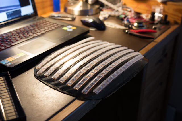
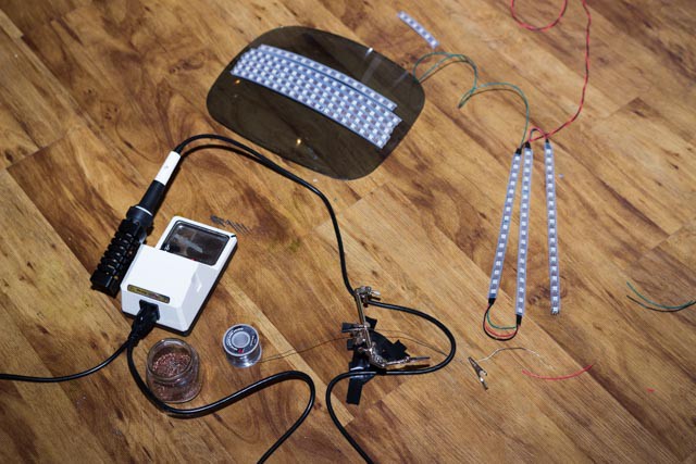
I laid out the strips in a serpentine manner. This is to reduce the distance that power is needed to travel. I also supplied another power line to the bottom two strips to help.
![]()
![]()
-
7Wiring up
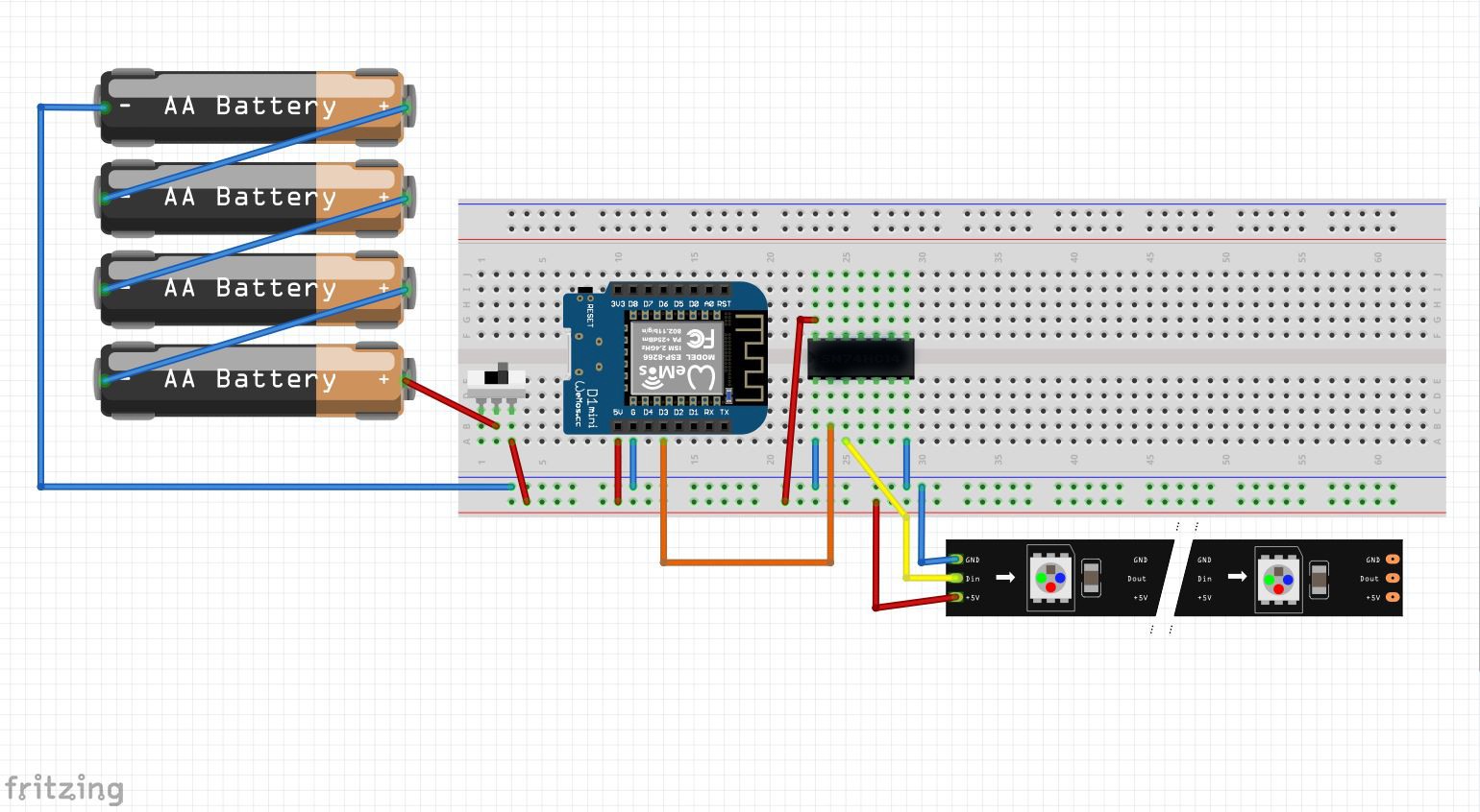
*Currently I am using Pin D3 on the ESP for the Data line of the LEDS.
The LED's run at 5V and the ESP's run at 3.3V. This can be a problem, so use a 74AHCT125 as a level shifter for the logic signal.
I used 4 NiMH batteries in AA format to power the head. This is due to 4 NiMH in series have a nominal voltage of 5V.
If running an ESP8266-esp01 you will need to run 3.3V to it otherwise you will over volt it.
![]()
Blue is ground
Red is 5v
Yellow and orange are data
Here is a sped up wiring video!
-
8Coding The LED's
See the FastLED library for documentation about programing the led's with Arduino IDE
#define FASTLED_ESP8266_RAW_PIN_ORDER
#define FASTLED_ALLOW_INTERRUPTS 0
#include <FastLED.h>
These lines of code attaches the fastLed library, but there are some critical things to add before the library is included. The library needs to know which pins are which on the esp8266. I found the RAW order worked for me.
While working with the wifi functionality, I found the led's started to jitter. This is due to all of the behind the scenes process of wifi occuring while the leds are being set with their new color data. The second line of code changes the importance of the LED programing, and stops interrupts from occurring.
#define CHIPSET WS2812B
#define NUM_LEDS 10
#define PIN D3
#define COLOR_ORDER GRB
Setting the LED information for the Library
CRGB leds[NUM_LEDS];


// Param for serpentine led layout
const bool    kMatrixSerpentineLayout = true;

// Use the "XY" function to generate the led number
uint16_t XY( uint8_t x, uint8_t y)
{
  uint16_t i;

  if( kMatrixSerpentineLayout == false) {
    i = (y * kMatrixWidth) + x;
  }

  if( kMatrixSerpentineLayout == true) {
    if( y & 0x01) {
      // Odd rows run backwards
      uint8_t reverseX = (kMatrixWidth - 1) - x;
      i = (y * kMatrixWidth) + reverseX;
    } else {
      // Even rows run forwards
      i = (y * kMatrixWidth) + x;
    }
  }

  return i;
}
These lines help to parse through the serpentine matrix for animations.
FastLED.addLeds<CHIPSET, PIN, COLOR_ORDER>(leds, NUM_LEDS).setCorrection(TypicalSMD5050);place this line into the setup loop to start the LED matrix
leds[XY( 13, 5)] = CHSV(color,sat,255);
This is an example of how to set an led to a color. notice the led is set by the serpentine array of numbers. The CHSV of the fastled is set by color, saturation, and brightness.
-
9IRC Code
** Edit ** Fredi released a new version of the ArduinoIRC library that is Twitch compatible, but needs some extra lines of code in the main sketch. He has a great example written for working with Twitch. Follow along below if using V1.0 of the library.
I pulled a copy of Fredi Machado's ArduinoIRC library to use. However, I found that it was not outright compatible with Twitch. I had to a section for oauth password in the IRCClient.cpp file.
boolean IRCClient::connect(String nickname, String user, String passw ) {
  if (!connected()) {
    int result = client->connect(this->host, this->port);
    if (result == 1) {
      this->nickname = nickname;
      sendIRC("PASS " + passw); //----------ADD THIS LINE to the .CPP File
      sendIRC("NICK " + nickname);
      sendIRC("JOIN " + user);
      this->isConnected = true;
      return true;
    }
    return false;
  }
  return true;
}
This sends the password to Twitch server first, allowing the rest of the communication to go through.
Now to include the libraries for the ESP and IRC Bot#include <ESP8266WiFi.h> #include <IRCClient.h>Don't forget to set your Twitch Server address, port, channel name, oauth password, and chatbot name
//Setting up the IRC Twitch Server information

#define IRC_SERVER   "irc.chat.twitch.tv"
#define IRC_PORT     6667
#define IRC_NICK     "chatbot"
#define IRC_CHAN     "#channel" // Include the # in front of the channel name here
#define IRC_PASS     "oauth:1234567890"  // You'll also need the oauth: before your password

//naming wifi and server client

WiFiClient wiFiClient;
IRCClient client(IRC_SERVER, IRC_PORT, wiFiClient);
The examples from Fredi's library can get you through the rest!
-
10Making it do Things
So the chat bot is connecting to Twitch and joining a channel, but how does it command the screen?
Within the Callback loop of the IRC bot, you can look for specific messages in twitchif(ircMessage.text == "!ch1"){ channel = 1; client.sendMessage(IRC_CHAN, ircMessage.nick + " set tvhead to the heart!"); //Serial.println(channel); }Within the Callback loop, set variables. The actual functions that change the tv screen exist within the main loop or within helper fuctions in code.
ATLTVHEAD
Atltvhead is a mashup of interactive art and wearable technology with a message of positivity and encouragement to let your oddities shine!
 atltvhead





Discussions
Become a Hackaday.io Member
Create an account to leave a comment. Already have an account? Log In.