RasmusB
-
CANPi Hello World!
03/14/2014 at 13:39 • 0 commentsI haven't had time to properly test my CAN adapter for the Raspberry Pi until now. In the picture the CANPi adapter is on the Raspberry Pi, and it is talking to the purple PCB in the middle of the picture. The red Arduino shield is only used to interconnect everything for this quick test.
![]()
-
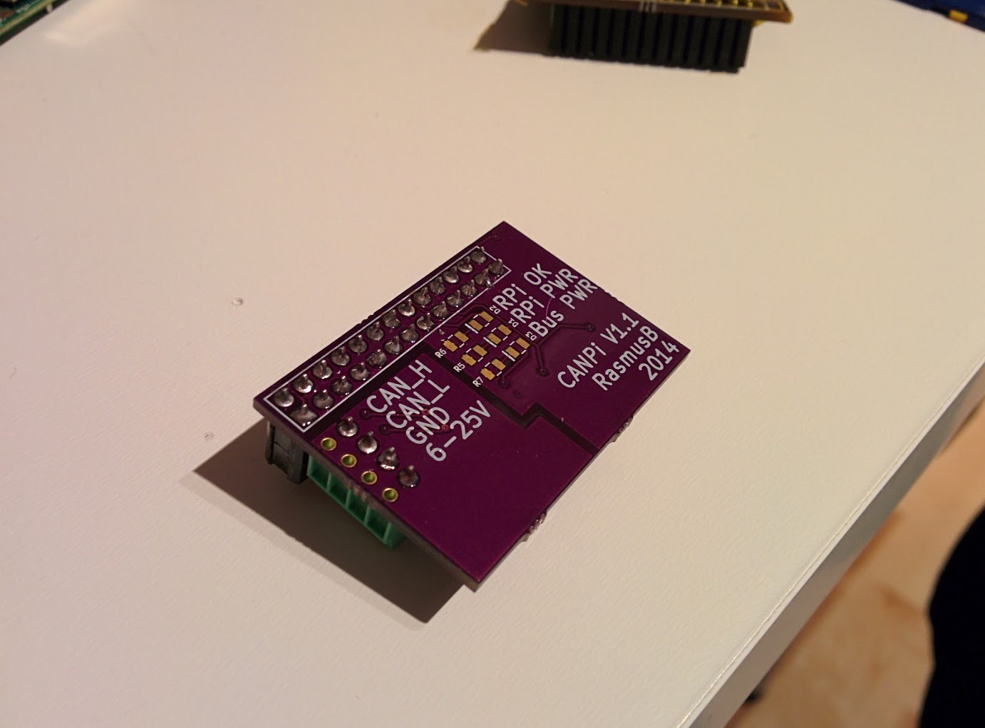
CANPi v1.1
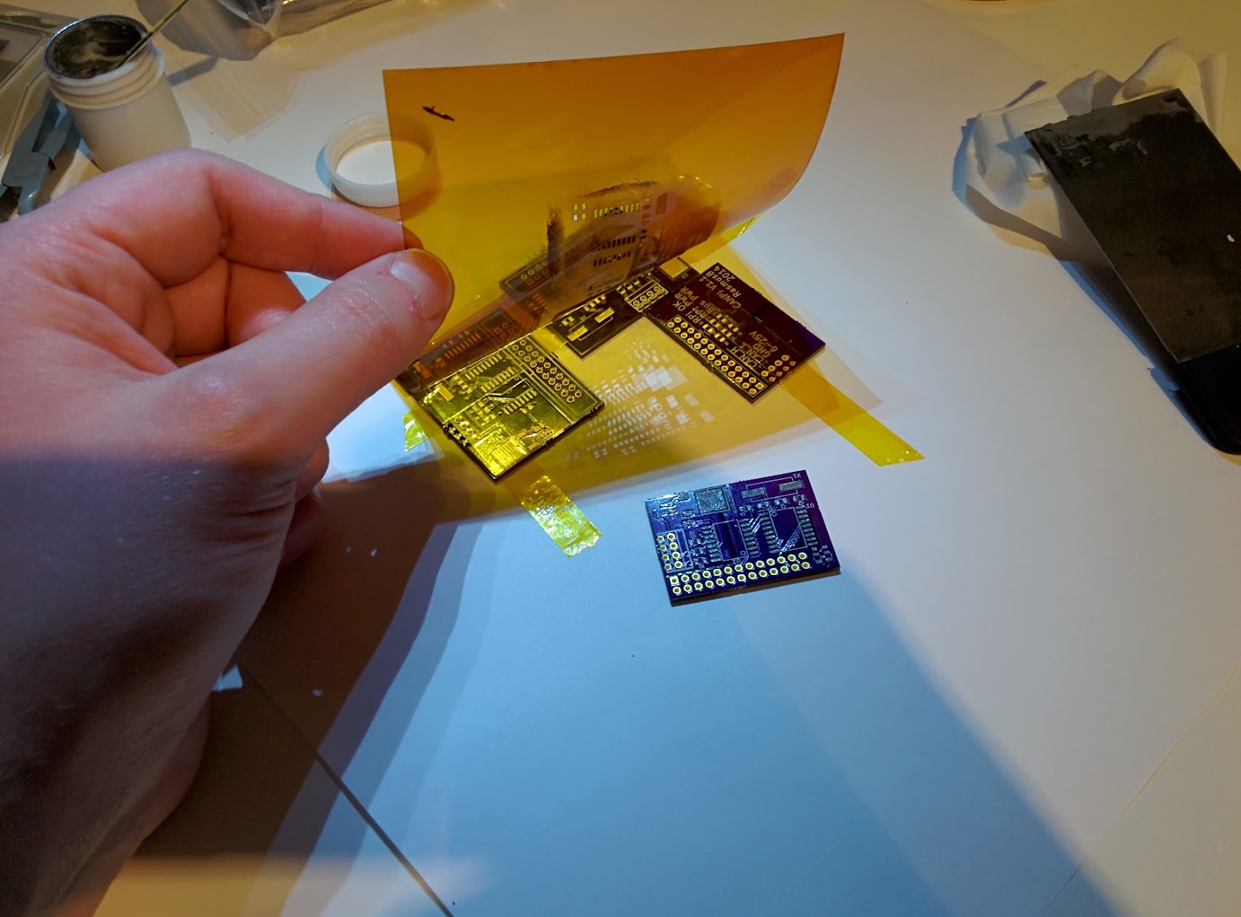
03/14/2014 at 13:38 • 0 commentsI got the latest revision PCB:s from oshpark.com today. This time, I also ordered a laser-cut mylar stencil from ohararp.com. I'm not planning on building lots of these, but I wanted to get more familiar with improvising solder paste printing at home.
My kludged together stenciling rig looks awful, but it worked well enough for a single board. The coverage was a bit uneven on some of the larger pads, but my poor squeegeeing technique is probably the cause of that.
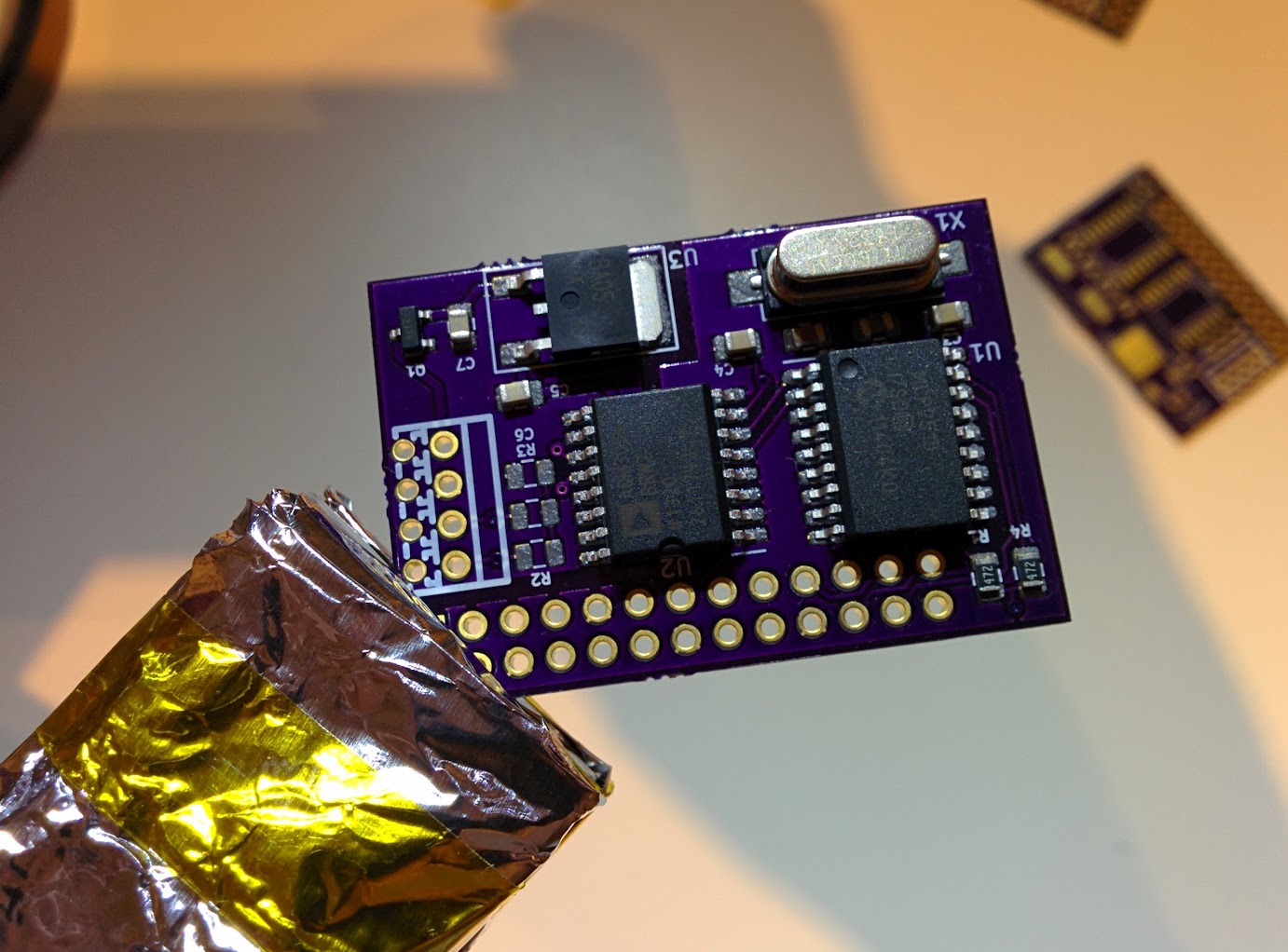
After shielding my plastic vice using kitchen aluminum foil and kapton tape, I used my hot-air rework station to reflow the solder paste. The components self-aligned as expected, and the circuit board came out pretty good!
Using a solder paste stencil was overkill for this project, but I thought it would be fun to try before i really need to use one :) By doing this, I realized that I need to come up with a more proper way to hold the stencil and PCB in place.![]()
I taped a few circuit boards together for support. Looks ugly but worked fine.
![]()
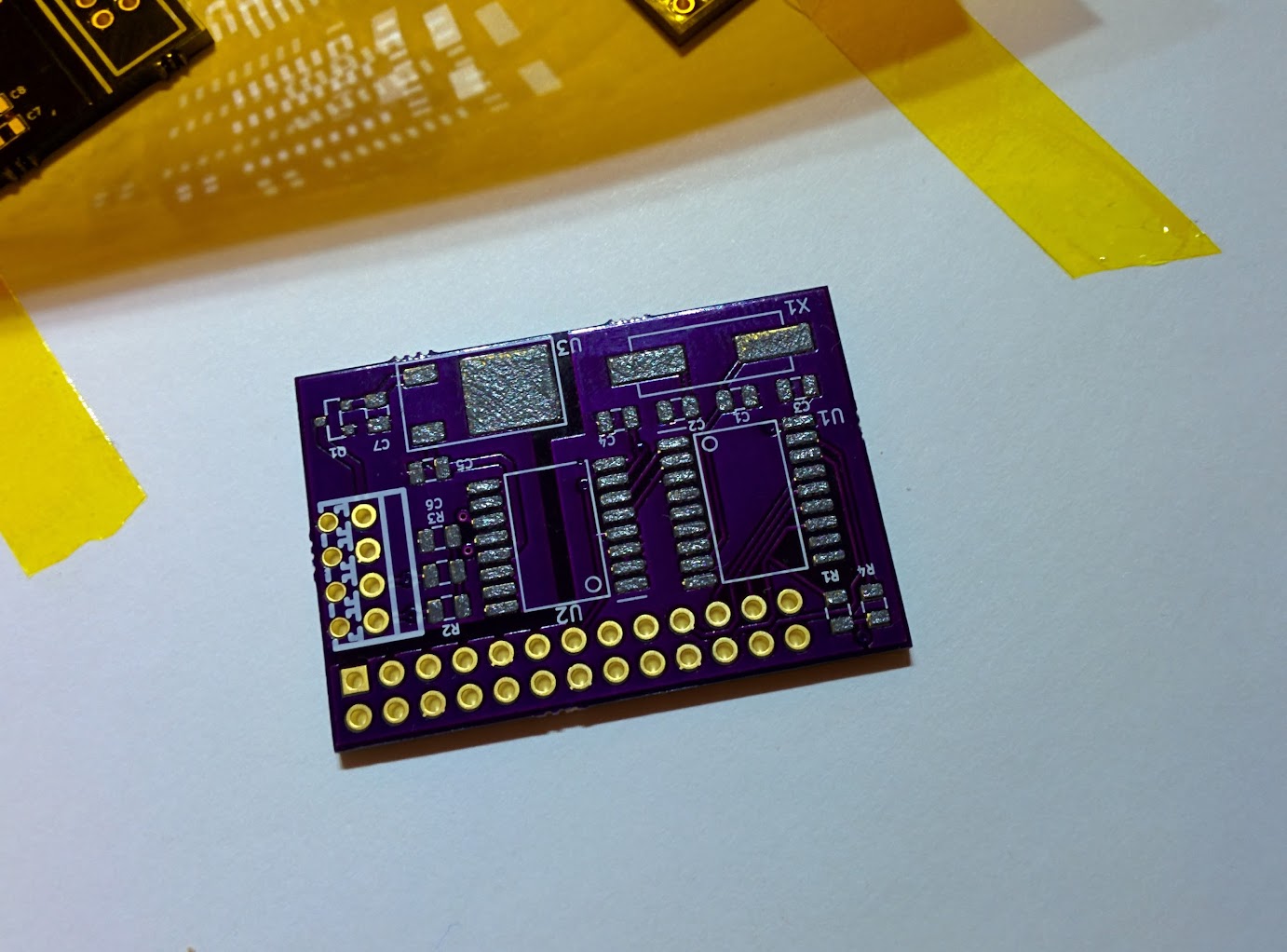
The top pads were unevenly covered, but I felt there was enough solder paste on all pads.
![]()
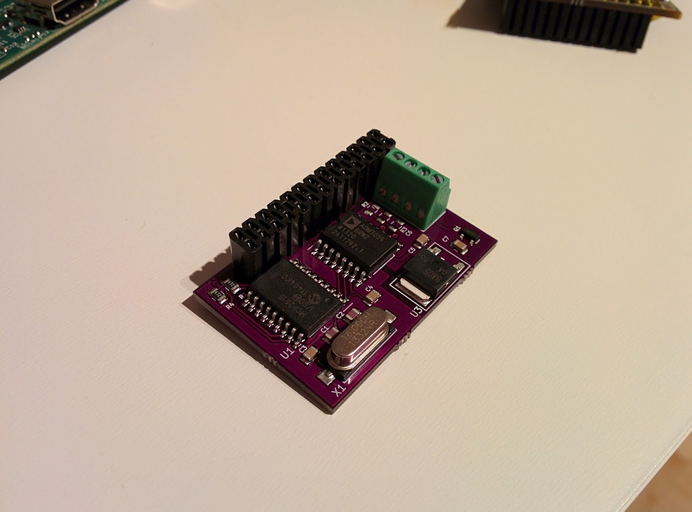
The components have been placed. R2, R3 and C6 are left unpopulated on this board.
![]()
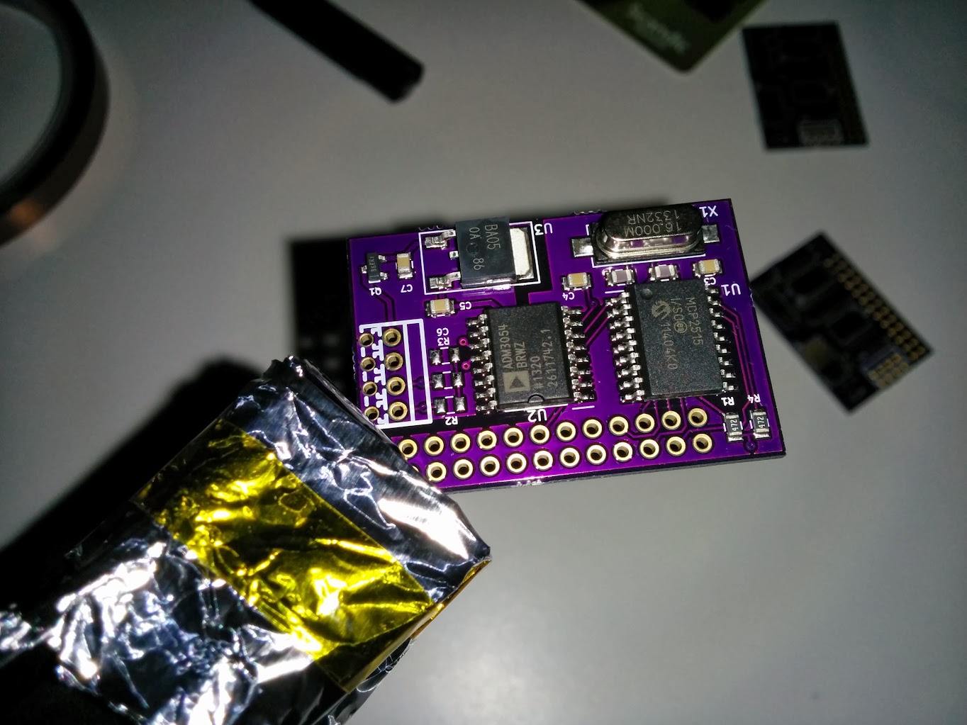
After reflowing with a hot air rework station
![]()
![]()
![]()
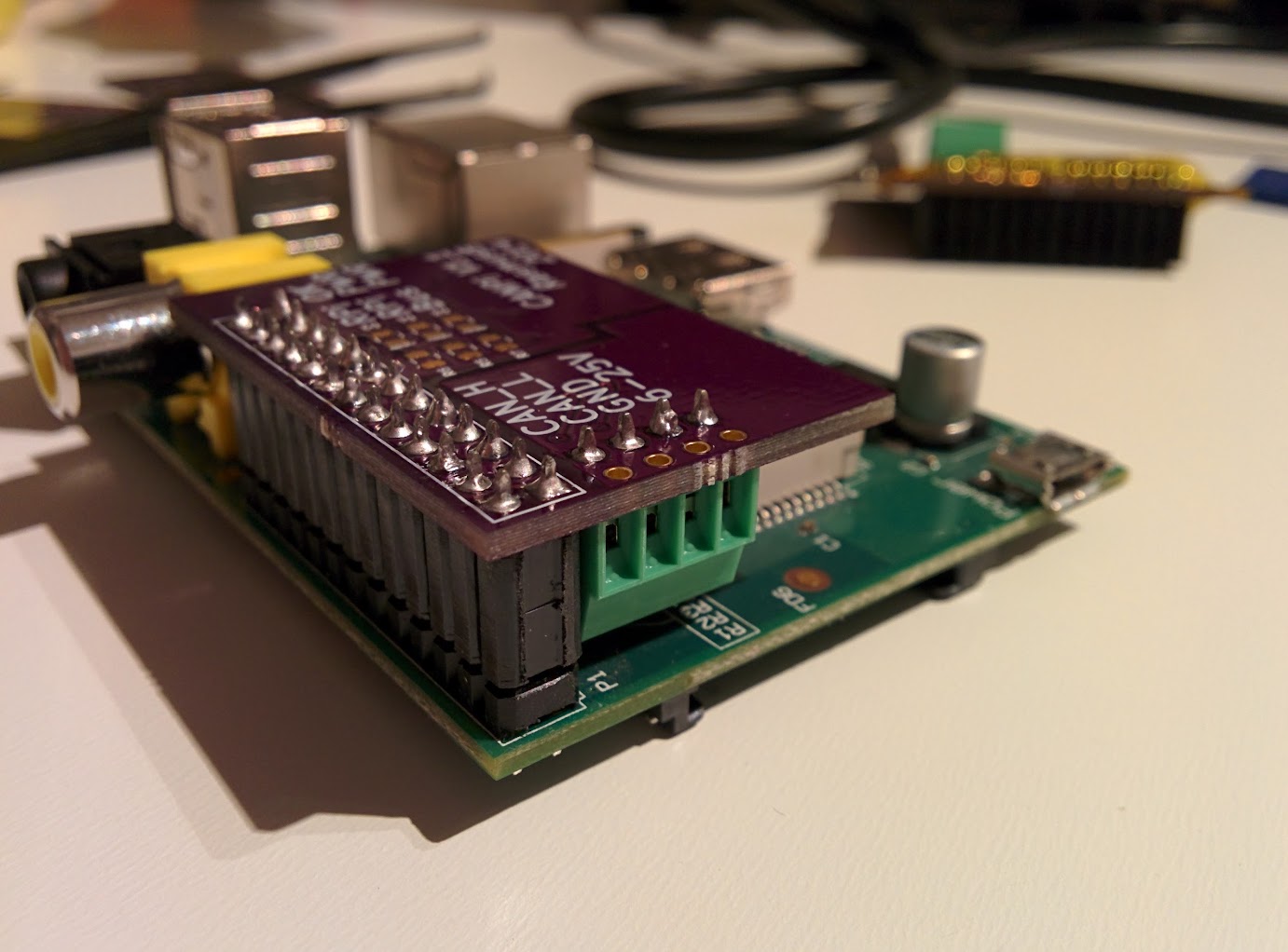
Careful measurements pays off. The new board fits perfectly within the RaspberryPi footprint.
![]()
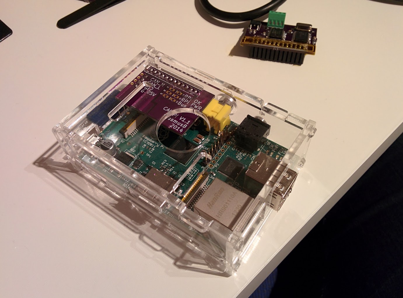
The new board fits perfectly in an unmodified enclosure.
-
v1.0 is always easy to recognize
03/14/2014 at 13:34 • 0 commentsThis is how you recognize a true V1.0 PCB. Not only sloppy soldering, but also green wiring and kapton tape on the board ;)
Well it doesn't have to look good as long as it is working! :D Now I know what needs doing to V1.1.
On a related note, using 0.1mm magnet wire (that's just under 4 mil for anyone in the
unenlightenednon-metric part of the world) is probably overkill for this job but that was all I had at home.![]()
![]()
![]()
-
My first add-on board for the Raspberry Pi
03/14/2014 at 13:31 • 0 commentsThis is a CAN interface, using an MCP2515 controller and an ADM3054 transceiver. The CAN transceiver is insulated from the controller and has its own voltage regulator. Input power can be anything between 6-25V DC and has reverse polarity protection. Also, having separate power supplies not only protects the Raspi, but also solves the problem of interfacing a 5V transceiver with the 3.3V system.
The next part is getting the kernel drivers working. Not my thing really, I prefer soldering ;)![]()