Eric Herbers
-
Featured!
01/27/2015 at 05:09 • 0 commentsFirst off, I want to thank Hackaday for featuring my project on the main page! It's a real honor for me, being a long time reader, and I was very pleased with the discussion that took place; it was very constructive.
As a handful of you picked up on I am not measuring lost packets; any of those results are rejected. I did dabble with packet loss to begin with and determined that was no good way to assign a good time value to a lost packet and handling them amongst the data was going to be troublesome. I've also played with trying to accomplish as many transmissions as possible within a time frame. That too did not work terribly well, I suspect due to limitations with the transmissions still being synced to clock cycles.
What I've been doing lately, at a very slow pace, is focusing on trying to filter data better before I begin to tackle multi-channel use; something I played with early on, but found requires some pretty extensive error handling in terms of telling the transponder to change a channel and confirming it happened. Often I could successfully make a channel change, but then never receive the auto-acknowledge... it's likely something I'll have to handle manually.
What I have done is temporarily gotten rid of using standard deviation on the raw values as I found using the true average yielded better results; using standard deviation often reduced the sensitivity to changes in distance. To help smooth things out, but still accomplish a decent refresh rate, I've gone to using a rolling average. So for instance I'm doing a test of 200 pings, and averaging 10 of them. It allows me to see a change in position fairly quickly, but still average out erroneous data. So far this is working very well; especially as I've placed some focus on trying to increase the number of significant digits.
I'm also just beginning to play with different data rates. Previously I was running at 250 kBps and have recently changed to 2 MBps to see how it works. At first glance it appears to offer more consistent results, but I've also made some changes to the rolling average programming around the same time so some A-B-A testing is necessary. Still, hopes are up!
-
Short update, no content
01/15/2015 at 03:24 • 0 commentsSo what next? Well, right now I'm using my old-as-dirt Tektronix 466 oscilloscope to take a peek at the chip enable signal from the micro controller and the resulting interrupt from the transceiver. Right off the bat I did notice that for every ping I was attempting I was actually send two... oops. Turns out that bringing the chip enable pin low as late as I was triggered the transceiver to transmit again once the interrupt was acknowledged. Bit of a waste of power and resources... and it'd also explain why the delay time between pings was suddenly important when it hadn't been previously. Moving the command to bring the chip enable back low a little earlier in code fixed that problem.
At this point I'm focusing on when I'm receiving the interrupt and how accurate the micro-controller is at measuring it. In my results I got a lot of erroneous results that were roughly 100-500 cycles later than others; an amount of variance I shouldn't be seeing. Through using the scope I can narrow it down to either the transceiver, micro controller, or potentially interference in the wiring (which I don't see right now). Time will tell!
-
Time for a Break
01/03/2015 at 06:33 • 0 commentsWhew, what a blur the last few days have been! I've been blessed with headaches and strained eyes, but I'd say this is one of the bigger under-takings I've done.
The project details have been completed (although the video is still processing) and final data results can be viewed there. Ultimately, after a healthy break, I plan to focus on doing multi-channel measurements and all the error handling that goes with that. Based on one of the white papers, this should help account for signal variances between channels and actually performs a bit of multi-path measurements... apparently 2.4 GHz does some funky things around objects.
Along with that I hope to get a better grasp on the time-of-flight measurements to further reduce variance and hopefully improve precision, but I fear I'm running into a brick wall with how the interrupt is timed by the transceiver.
Thanks you all for your interest and I hope you find this useful!
-Eric J. Herbers
-
Hours to go!
01/02/2015 at 18:37 • 0 commentsWell, I'm glad I didn't give up... things are improving!
I'm still using single-channel transmissions and as far as the deadline goes, that will stay. I did begin streaming data to Excel using Parallax's PLX-DAQ macro which greatly sped up my development pace as I could stream raw numbers to excel and apply calculations there; much quicker than constantly flashing new code, performing a short log and reviewing what is essentially a snap-shot of data.
While I never could get rid of some raw results that strayed far from the area of interest, limiting results to a window and weeding out the ones that fall outside standard deviation produces some fairly nice results, greatly reducing the jitter I've had before. I've also refined the interrupt handling on both ends to reduce (hopefully eliminate) some problems that would cause the transceivers to stop working if the data connection wasn't strong. Now, even in the noisy office, I can stray up to at least 40 feet with no loss of connection, even through a wall and buried in a library of books.
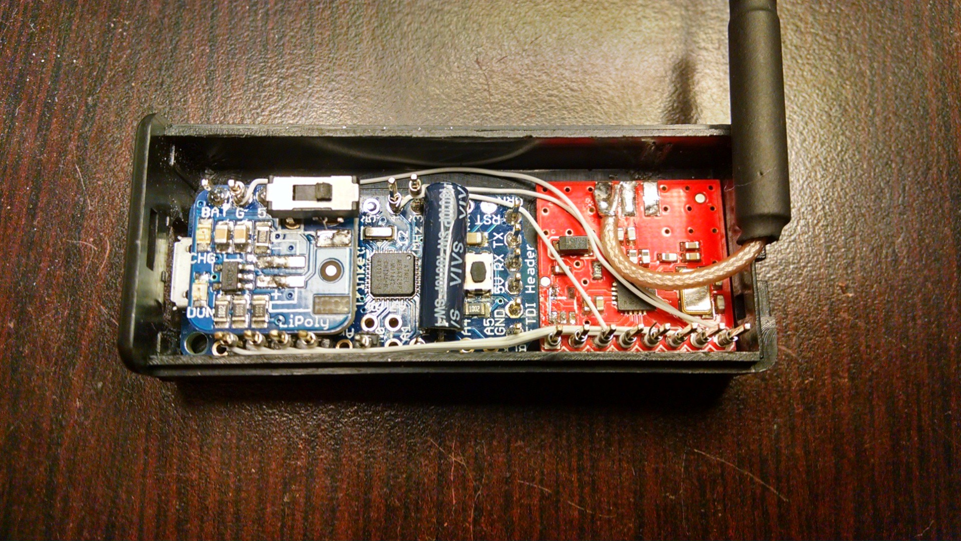
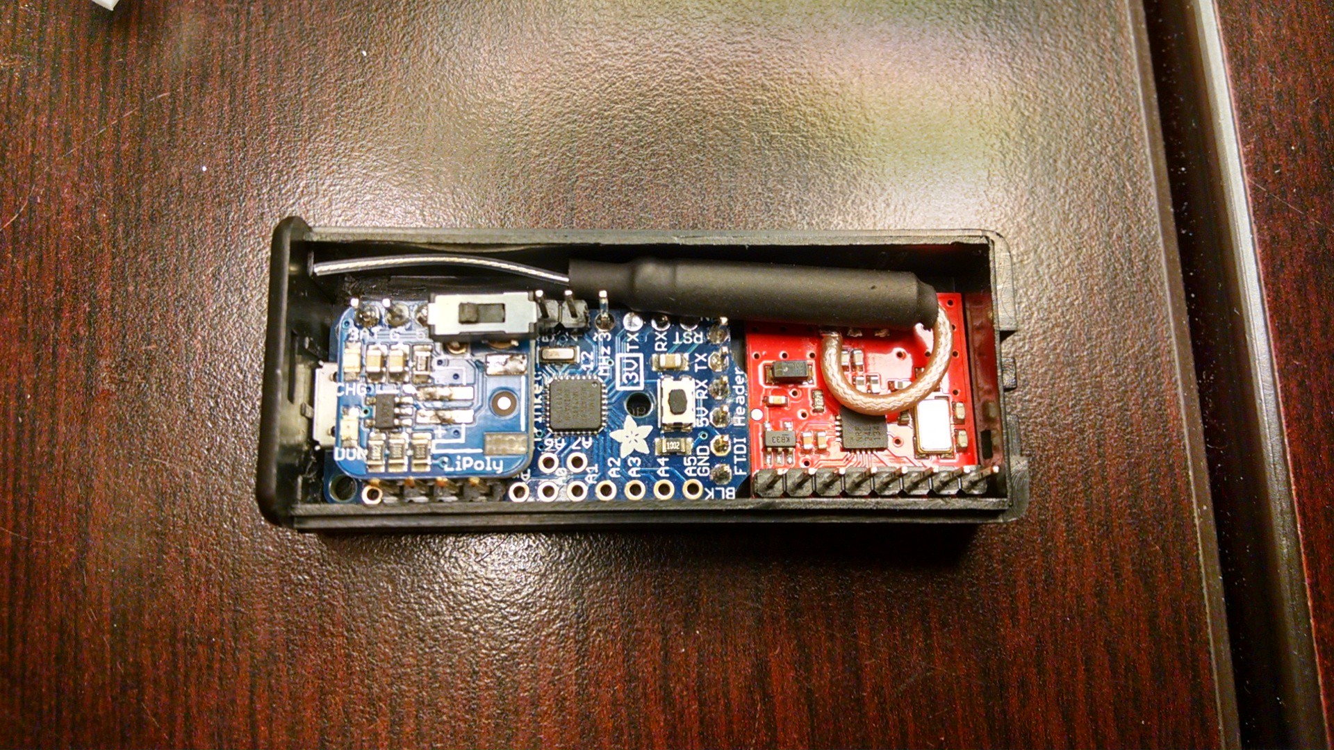
I also took some time to wrap up the hardware and managed to squeeze everything into a 2xAAA battery case... I recommend 2xAA next time. Due to the tight spaces, I ended up wire wrapping the two boards together. All in all it fits into a nice little package and doesn't seem to hurt reception too badly; although code was the biggest problem in that regard.
I've also added a small vibration switch that will ultimately be used to trigger the transponder to send a start message once motion is detected; the aim being to conserve power when at rest. With this case I can manage to fit a 150 mAh battery which provides at least a few hours of battery life; hopefully more once I try to integrate a power saving mode. However, that won't be complete in time for the deadline.
![]()
![]()
-
Short update
01/01/2015 at 21:28 • 0 commentsThere's hope! Lots of refinement to do, but as far as having a working concept by the deadline... there's hope.
So what have I done? Well largely try several dozen different ways of attempting the same thing and tweaking the software to improve timing and reduce standard deviation of the results. In the end I toyed with timing a single transmission and attempting as many as possible within a set window; both single channel and multi-channel. After reading both the white papers I have linked, I decided to focus more on timing singular transmissions as both papers indicated that averaging the results was their end means.
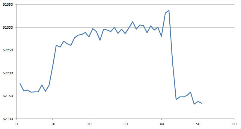
Sure enough, sending 1000+ transmissions produces some interesting histograms that do show a trend. While I haven't been able to prevent outlier data, I have decided to at least limit the used results to a specific range which has improve the averaging results greatly. The downside is that due to the number of rejections, trying to get 1000 good samples can take up to 10 seconds... that needs improvement.
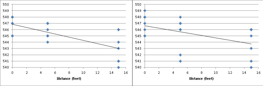
Regardless, here's a handy graph! After taking 5 or so samples, I would move the transponder further away from the receiver. Measurements were taken at <1 foot, 3 feet, 8 feet, 12 feet, and somewhere around 15-16 feet, around a corner and down the hall before returning to 0. All but the furthest were taken line-of-sight and the results show that the further away you get, the more deviation is seen in the results. The results are also very non-linear below 3 feet.
![]()
-
Still Alive
12/30/2014 at 16:23 • 0 commentsNo, I'm not dead yet! December has just been a busy month thanks to my marriage and the holidays. Needless to say, I haven't been able to do much work on this until the last 5 days or so.
That said, I've got hardware together and after many many hours of banging my head against a wall, I've finally got the transceivers talking to each other. Let's just say you should take great care when copying register writing commands to make sure the register location was changed... I have a feeling I blew a good 6 hours thanks to that. Let's just say it's a good thing I'm not a professional.
Despite that hurdle, I've managed to rough out some programs and have come away with some interesting results. Largely what I'm doing is sending as many transmissions as I can in a controlled period and logging how many were successful. As it turns out, to make use of Nordic's handy auto-acknowledge feature the receiving end does need to read the receiving FIFO before the auto-acknowledge packet is returned; so both ends of the link need to take an active part.
Using this method does yield fairly reliable results, but the trouble is that when operating on a single channel the results don't change much when distance is increased. I believe this has a lot to do with what I've discussed previously where the transit time is swallowed up by the relatively slow clock time of both ends.
The interesting bit is that performing the same test over multiple channels, as discussed in some of the white papers I have linked, is reasonably successful and can produce fairly good results. The trouble is that what I'm largely doing is in essence a site-survey and rather than accumulating the time it takes a signal to transit from one end to the other, I'm actually measuring the packet success rate.
This is fairly obvious when I test the setup at home and get a higher number of packets transmitted versus when I try it at work where there are more sources of interference. At home I can get nearly 100% success rate up to ten feet away (making any measurements useless under that distance) while at work I'm lucky to manage 100% at one foot.
Still, with some processing of the data I can get fairly consistent results, but any calibration certainly has to be done on-site and couldn't be relied upon elsewhere. Long story short, the results are a bit disappointing. I intend on continuing to refine this a little further, but the end result doesn't work remotely how I had intended and may prove to be too unreliable.
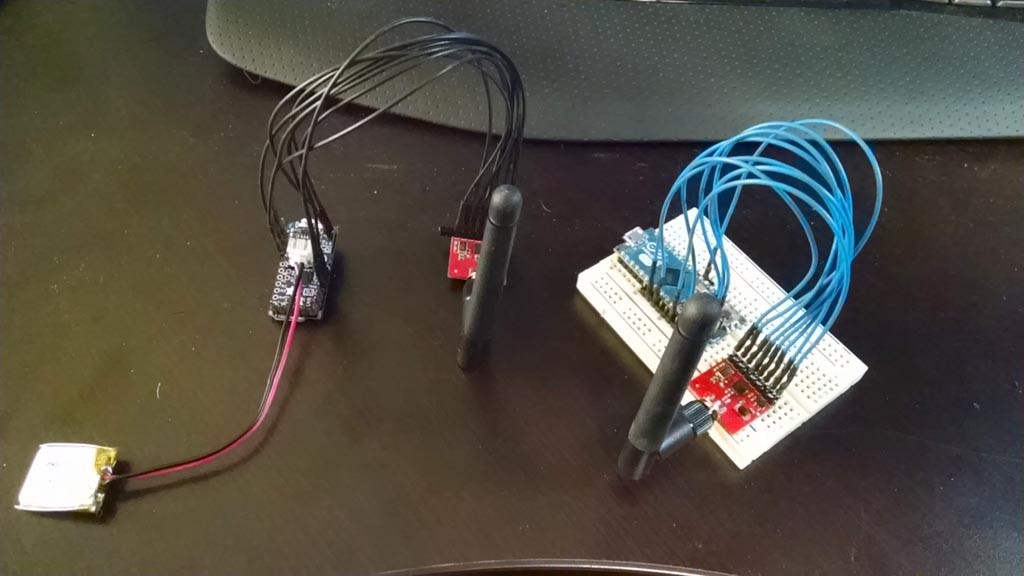
![]() Hardware cobbled together for testing. Ultimately I intend on fitting the transponder into a AAA battery case and direct soldering the antenna to reduce the footprint.
Hardware cobbled together for testing. Ultimately I intend on fitting the transponder into a AAA battery case and direct soldering the antenna to reduce the footprint.![]()
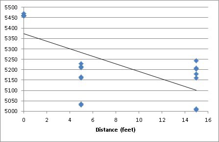
The same test performed at a different time of day. You can see there is a trend, but it has a large spread.
![]()
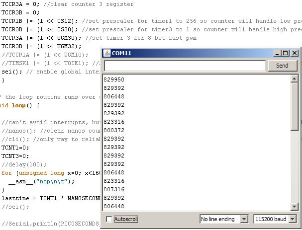
The same basic test again, but this time performing some logic against the result to weed out results that stray too far from the average, then re-averaging the results. In this case I did reduce the period for pinging which reduced the precision, but also greatly reduce the time it takes to perform the test. There's obviously a fine balance between the two.
-
Grim Outlook
12/08/2014 at 19:31 • 2 commentsI've finally got my components, but between trying to sort out the logic for the software and getting ready for my wedding next weekend (I swear to god if someone says the word "excited" again I'm going to snap) I haven't gotten around to wiring anything together or trying more code.
So far I've been simulating the rough logic in Excel and coming to the conclusion that this is going to be a bit more work than I imagined. Once you begin considering that any action taking place outside the microcontroller still has to wait for a clock cycle, many of the proposed ideas for how this could work likely won't.
It's two the point where I either need to start slinging code just to verify something isn't going to work (as opposed to dismissing it) or come up with some other, more hack-worthy, solutions.
One of those solutions is to change the clock speed of one of the microcontrollers. You see, right now everything divides well into 1 (16 Mhz has a clock tick of 62.5 ns, 12 mhz is 83.333~). If I could fudge one to say, 15.8 mhz I could rely on an interesting phenomenon to make this work.
I won't go into the gory details because any attempt to explain them so far have turned into a mess, but by having the transponder operate at a slightly different frequency than the receiver, we can essentially make a vernier scale that can be used to measure time in a very precise manner.
The challenge is that this is only possible by either replacing the crystal with something very non-standard, or relying on the internal oscillator and changing the OSCCAL (Oscillator Calibration) value to shift the frequency. The question is whether the internal oscillator can be stable enough to use and how to apply a calibration procedure intermittently to it to account for temperature changes.
-
New challenges and I don't even have hardware...
12/03/2014 at 04:57 • 0 commentsTriggering PSRSYNC under the GTCCR register did the trick for resetting the prescaler and getting consistent timing results. Unfortunately while researching that this morning, another thought plopped in my head that could be a potential deal-breaker.
The entire concept was to have the transponder send a signal and the receiver to bounce one back, incurring a delay due to the distance between the two. The problem is that you're still relying on the system clock to get around to acknowledging a signal has been received and responding back. Any delay between the data received interrupt being triggered and the microcontroller registering it completely nullifies your ability to accumulate that delay.
To give an analogy, it's like giving your friend a call, but they can only answer the phone at ten minute intervals (IE 5:30, 5:40, 5:50). As far as they know, they received the message at 5:50, but you could have sent it at 5:46... Just like the transponder, it can send the message at anytime, but the receiver still has to wait anywhere from 0-62 ns before it can acknowledge it and send another back. You can repeat your call at 5:59, but it's still 6:00 before it gets picked up. No matter how many times you repeat, what delay you created gets reset to a standard interval by the receiving end.
I think what I may have to do is change to sending messages of different lengths and increasing the length until I roll over to the next count of the timer. This way I can attempt to line up the interrupt triggering the moment it can be registered. At that point a combination of the message length and the time-of-flight can be used to calculate distance.
In other news, I'm beginning to like the Leonardo/Micro platform. With the 32u4 chip, there is a high speed timer that can be clocked off the PLL clock... at 64 mhz. Pretty handy as it gets resolution down to 15 ns, but I likely won't use it. Ultimately I want to develop a solution that works on any Arduino platform and doesn't cater to the strengths of just one.
-
Interrupts Can Really Suck
12/01/2014 at 18:52 • 0 commentsThe holiday weekend was full of moments of success and frustration. I refined the program to produce accurate numbers and began testing how consistent the new timer was, only to find it wasn't at all. Concerning the interrupt used to count how many times the overflow has occurred, there were zero problems. However, trying to get a consistent number from the counter proved to be troublesome.
It's obvious in hindsight, but when you're trying to count per the tick of the CPU clock, any other interrupts that are running can really screw with your results. Typically I was able to pull reasonable numbers on the microsecond scale of slightly better resolution than micros(), but variance at the nanosecond level was completely unacceptable. It was bad enough that using the micros() function actually produced marginally lower standard deviation... ouch.
Ultimately, disabling global interrupts would produce dead steady numbers from the Timer 1 counter. While I can work without interrupts, that also means the overflow interrupt is no longer enabled and I would have to "manually" watch the counter overflow. Sounded like a big waste of resources to me.
So ultimately I have two options to sort through now:
Option A: Pinpoint the offending interrupt(s) and disable it(them) temporarily while still allowing global interrupts.
OR
Option B: Use a combination of Timer 1 and Timer 2 to count nanoseconds without the use of an interrupt. It dawned on me late last night that I can configure Timer 1 at a prescaler of 256 and be able to count up to a full second before it overflows at a resolution of 16 us. I can then set Timer 2 at a prescaler of 1 and be able to count from 62.5 ns up to 16 us before it overflows. Between the two of them I can get accurate timing up to a full second at a resolution of 62.5 ns without the use of interrupts.
I'd still be disabling global interrupts, but based on the communication requirements of the Nordic transmitters, I don't believe that would make too large of a hurdle.
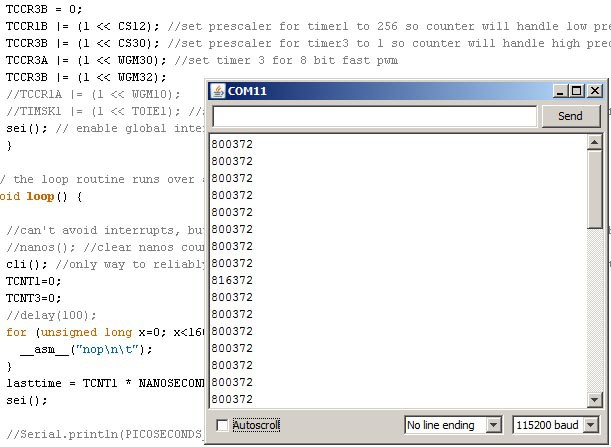
Edit: The Trinket Pro and transceivers are now ordered. Hopefully next week I'll be able to get some hardware brought together. I've also attached screenshots illustrating the effect interrupts have. Both are using the Option B timer scheme which still has some odd variance in the low resolution counter.
![]()
![]()
Edit 12-2-2014: After reviewing the datasheet for the Atmega32u, it clearly points out that it may be necessary to sync the prescaler with the code... that'd explain the intermittent timing error of the low resolution counter that I was seeing. Using the GTCCR register, I can clear the prescaler at the start of my timing event to sync it up. Otherwise the prescaler may trigger right at the start of the timing event, or a while later leading to the inconsistent behavior.
The only downside is that syncing the prescaler affects all three timers tied to it so it would introduce errant behavior into the millis()/micros() functions, but as long as I'm aware of that when writing the program, it shouldn't be a problem.
-
Testing the Waters
11/29/2014 at 04:55 • 0 commentsSo far so good. Screwing around on the Arduino Micro I currently have, I successfully tested a nano-second timer which should be accurate down to about 63 ns. I'm relying on Timer1 in fast PWM mode to run at a pre-scaler of 1; causing each tick to increment with every clock cycle. At 16 mhz that's 62.5 ns. The only downside is that as-written it's limited to counting 4.2 seconds, but that should work fine for this application. Now I just need to work on making it compatible with the odd-ball 12 mhz platforms; otherwise 8 and 16 mhz results in nice round numbers and no chance to accumulate error.
This is borrowing heavily from the code already used for the micro-second timer, only a little simpler and designed to reset the counter at every call of the sub-routine due to the nature of how it's being used and how short it can time for.
Radiolocation using Pocket Size Transceiver
Let your home automation know which room you're in, your car to know if you're nearby or any other need to detect proximity over a range.
 Hardware cobbled together for testing. Ultimately I intend on fitting the transponder into a AAA battery case and direct soldering the antenna to reduce the footprint.