-
Pavapro 2 is alive
09/07/2015 at 20:22 • 0 commentsIt's been quiet here for a few months, as I had just a little time for hobbies, though the project was moving on, slowly, look:
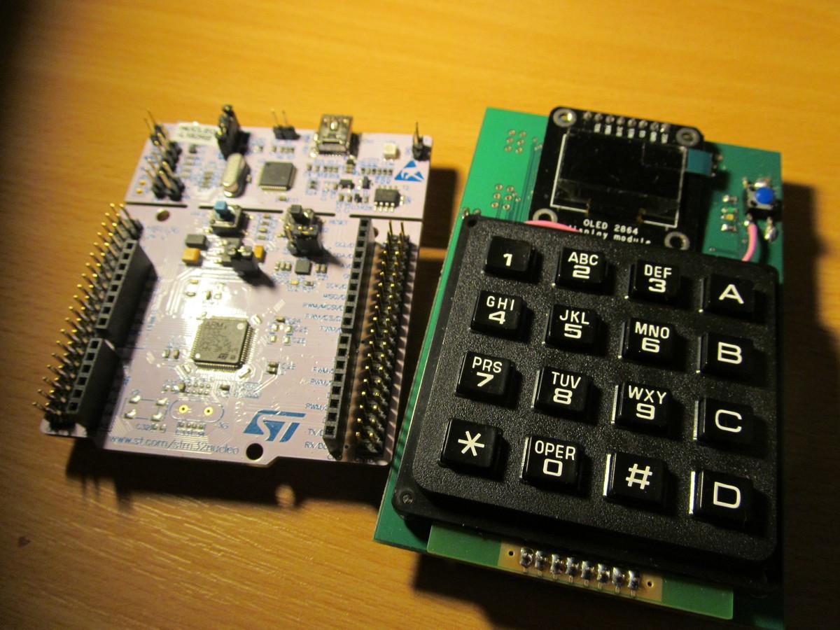
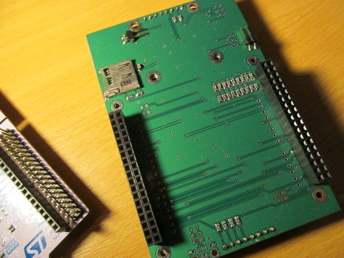
I made an expansion board for STM32L152RE Nucleo board.
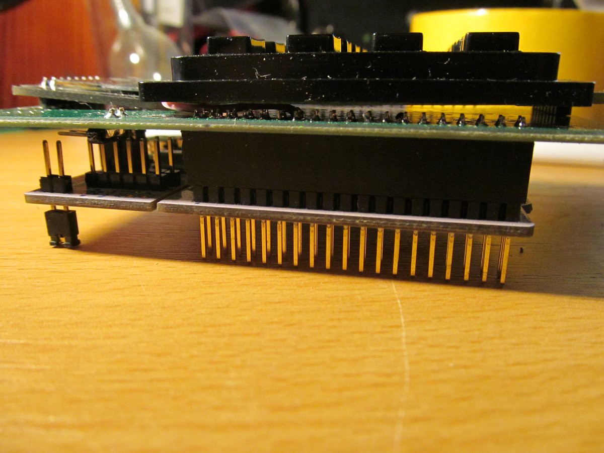
And it is stacked in usual boring way
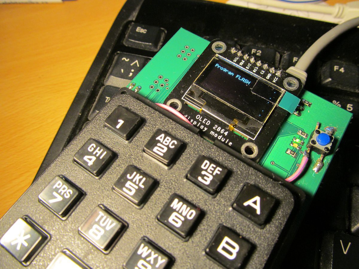
But it is alive!
I'm thinking of changing display type. That OLED is nice, but its tiny compared to keyboard and has high power consumption. If I'd change display to something bigger, the OLED screen would take much more juice. Seems like little TFT displays could use less power - like the usual 160x128 pixels I used in #JJ Tricoder and #10$ curve tracer projects.
It seems to be happy with a few miliamps of power for background LEDs, having the biggest share in total display consumption. I considered also EADOGM128 monochromatic display, but the price seems to be quite high. The 160x128 TFT is on ebay for 3USD or thereabouts.
-
What's next?
01/18/2015 at 21:26 • 2 commentsThough Pavapro in its current form will not be not much developed, I strongly think of Pavapro 2. I looked into documentation and searched for FLASH programming of various MCU's. What I found it would be doable for:
- PIC16F1xxx
- PIC18F (including PIC18FxxKxx and PIC18FxxJxx)
- PIC24
- PIC32
- MSP430
- AVR (it is currently done for AVRs with equal or less than 64kB) with unlimited FLASH and ATtiny10 and friends
- AT89 - x51 MCUs
In fact, the programmer part of pavapro wasn't the hardest one. The task would be further simplified by borrowing code from my previous projects: the 8-bit PIC from #1757. PP04 - Camel computer and AT89 from PIC89PROG
I'm a bit reluctant about JTAG. I feel like it's not going to be rocket science, but anyway, implementing JTAG would allow interesting games, like
- svf player for programming programmable logic
- various ARM support
As a result of my love affair of 68HC08 MCUs (before Freescale obsoleted them in short time - lesson learned: never use any MCU from Freescale again) I'm probably going to implement them too. So,
- HC08
More device support is possible, but not in first plan for now
- STM8
- serial memories
Above that all, Implementing not only programming from SD card, but also receiving the programming file from serial line (or USB) would allow to use pavapro2 as quite universal device programmer. Just send hex file into serial port from whatever with serial port (your PC, raspberry, phone, type it into ASR33...) and wait a moment.
What I would definitely change is MCU in pavapro2. Honestly, AVRs are not that convenient to program as I'm used to (PIC, ARM). No debug support in Linux (AtmelStudio based on windows-only Visual Studio, what a cruel joke in year 2015) and various little, but painful nuisances like "pgmspace.h" or annoying fuses (No RSTDISBL, no fun!), sometimes rendering your MCU into OTP part and your device into brick.
In fact, not much of horsepower is required here - ATmega328 was sufficient, in this field. However lack of RAM and FLASH was showstopper for my development. 32k of FLASH was too small, 64kB would be better and 128kB or more is king size. 2kB of RAM was compromise, some 8kB would be nice, but I feel like 32kB or more would be great. I'm not sure whether I'm going to use PIC32 (my favourite PIC32MX795F512H or even new PIC32MZ with half a meg of RAM) or ARM MCU (venerable LPC1769, maybe something newer, like LPC11U68).
Anyway, I want to keep the hardware not more complicated than it is now. I don't want to grow it into huge behemoth.
I'm going to let this idea to mature and see how it turns out.
-
Result of Trinket EDC Contest
01/07/2015 at 22:43 • 0 commentsThis project won second prize in Trinket EDC contest. Great!
Thanks to all who followed/skulled this project, this feedback was valuable and helped me to put more effort in the project.
-
Résumé
01/03/2015 at 18:25 • 0 commentsWhen I wrote my first thoughts project log more than month ago, I had no idea whether I'll be able to cram all the functionality into single ATmega328 contained in Trinket pro.
Fortunately, thanks to quite high code density of AVR code, as well as writing in plain C and great fatfs library I used in my project, the goals were met - so I can write the FLASH of target MCU from pavapro, set up fuses, edit and assemble small programs (and acting like small micropower AVR IDE), you can use it as serial terminal, crude e-book reader or you can have shopping list here and look like ultimate nerd in bus or in your favourite coffeehouse. It all took a solid piece of code (more than 3000 lines of code, not counting all the temporary testing code) resulting in full Trinket pro FLASH memory. All what is left is 20 bytes out of 28kBytes of FLASH... the last lines of code were a bit tough, I had to adjust code written previously, to free up a few dozens byte here and there for new code. Looking back, the pavapro seems to be more software than hardware oriented project, though hardware gave me some headaches too. Except of a few design flaws on the PCB (fixed in current HW files on github) and some incorrectly ordered components, I had problems with my 3D printer, that broke one day before deadline. In fact, it was night before deadline, as I'm doing most of the development during the nights, when my 1,5r son is finally sleeping and I have time for my hobbies. It can be seen also on my photo album - I set up for all the photos that didn't get into project logs and the others are in original resolution (I down-scalled all the pictures before uploading, to save your bandwidth when viewing project logs) - where most of the photos are slightly yellow-ish. Meh.
Though, there is a single thing I didn't make until contest deadline: absolutely simplistic and cut-down version of pavapro, without display or proper keyboard - though there is solid ground for building such as device. All necessary routines are already there and working, in fact it is more question of deleting code than writing a code. I had also other plans, for the case when I wouldn't be so FLASH starved - like BASIC or BrainFuck interpreter, I think it would go nicely with the spirit of pavapro.
Now I can consider the project mostly finished and closed, mainly because of the fact the ATmega328 in Trinket pro is full now. I believe some optimization could be used to free a few dozens or even hundreds bytes of memory, nonetheless to bring some more features, more FLASH would be needed. I'm not aware of any 28-pin AVR with more than 32kB of FLASH, compatible with ATmega328p and moving design to ATmega644 or similar would have significant impact on the hardware.
After all, developing pavapro was a great fun, so the meaning of contest was probably fulfilled. I spent nights learning new things, resulting in my own mini-computer, ultimate nerd status symbol and finished open-source project with 100% usage of FOSS development tools.
-
Want to build one?
01/03/2015 at 14:44 • 0 commentsYes, you can. Basically, you have three alternatives with decreasing difficulty level:
1. Use fully populated custom PCB:
That is the variant I chose for my device. It includes soldering AVR in QFN package, so some degree experience and laboratory equipment (though cheap one) is needed.
Eagle schematics and PCB layout, as well as schematics in PDF or PNG formats for simple viewing are available on github.
2, Use custom PCB, partially populated with easy to solder SMD parts and factory made Trinket pro.
This is somehow easier alternative, as all you need is a bit of steady hand. Take the PCB, ignore the dense middle part containing Trinket pro "clone" and solder the real Trinket pro via pin headers. Then populate the rest of SMD components. Don't worry, no QFN packages.
3, Don't use custom PCB at all.
You can choose this alternative, when you don't feel like SMD soldering is for you. Just take schematics and take look at the blocks. You can see Trinket pro 3V and LiIon backpack sections and replace it with factory made Trinket pro and LiIon backpack. In the original schematics, the other parts are SMD components, but with through-hole counterparts available too.
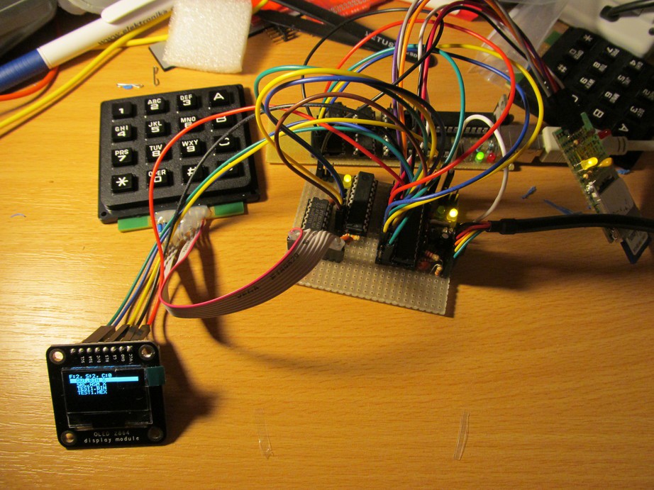
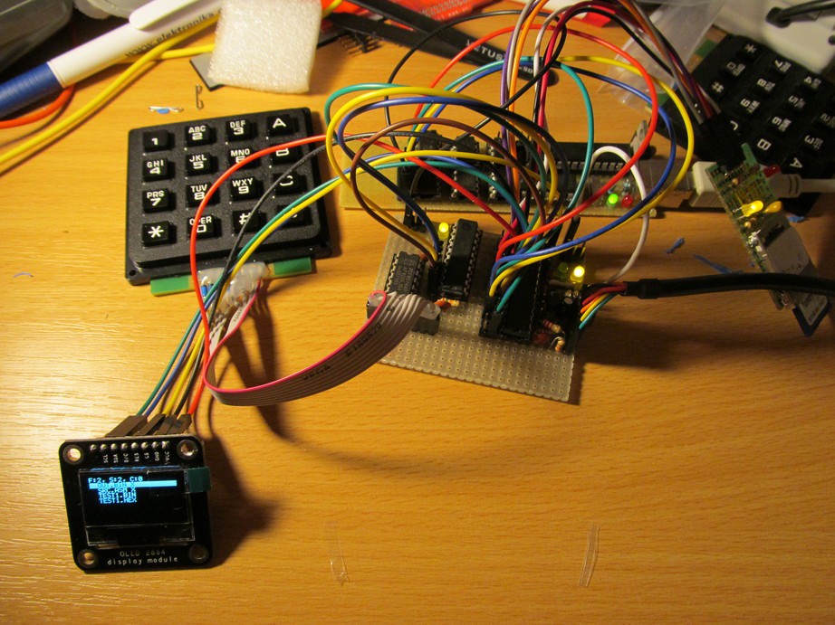
By the way, before could lay my hands on the real Trinket pro and my PCB, I did all the software development on my temporary PCB, assembled on pieces of protoboard.
![]()
Disregarding what hardware you use, software can be found on github easily to build and load with arduino IDE.
Happy hacking!
-
It works!
01/03/2015 at 00:57 • 0 commentsI printed the case and settled Pavapro PCB into it, added battery and now it seems to work as expected. I had to fix a few minor bugs, though.
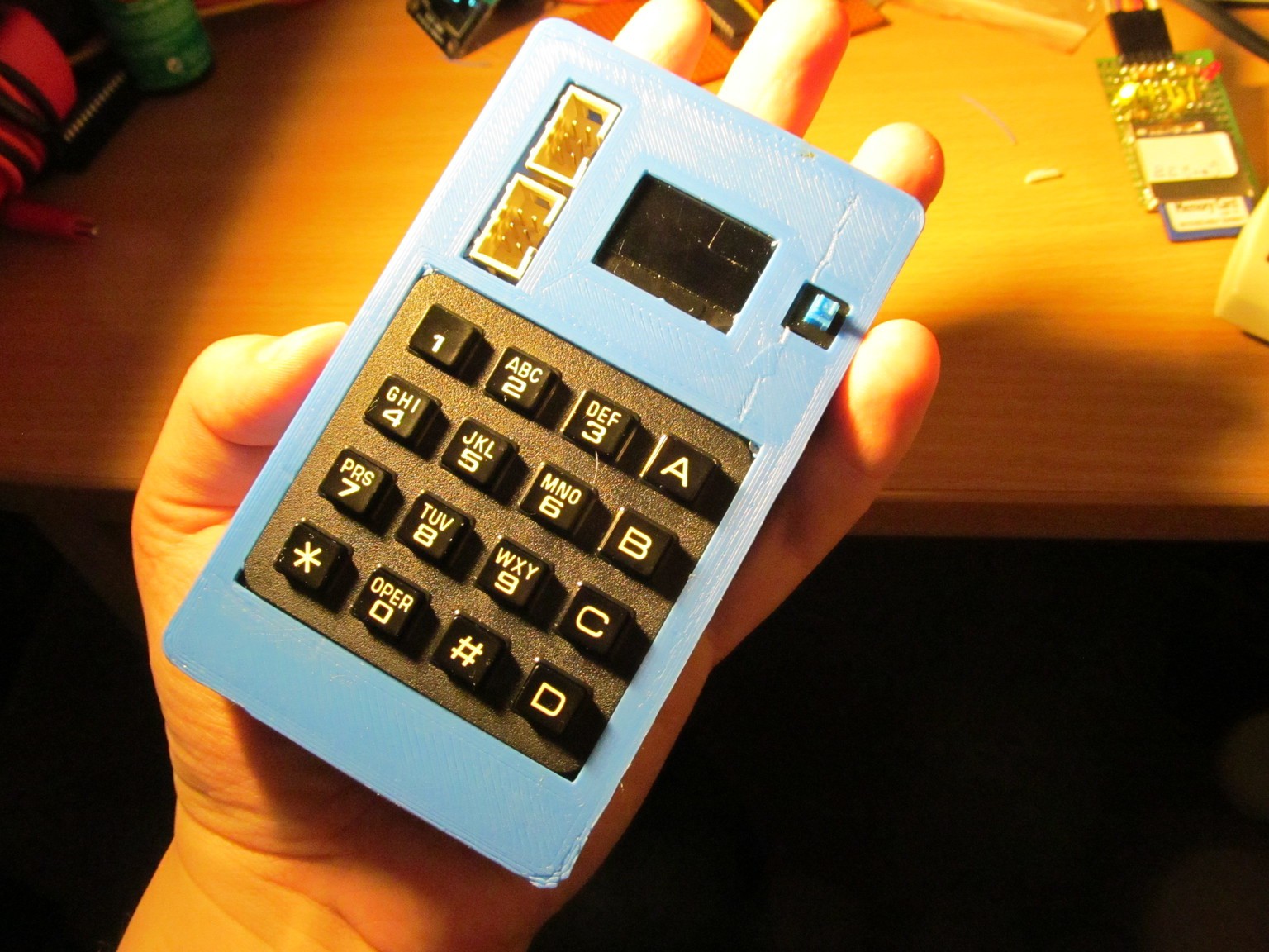
During the print, thermistor on my 3D printer's hotend lost contact, regulator cranked up temperature to the point where hotend started to melt, rendering my printer unusable. You know, day before deadline. Fortunately I had some spare hotend, though giving me horrible results, I managed to finish the case for pavapro. This is how it looks
![]()
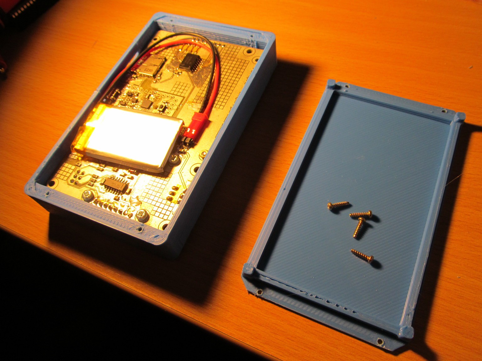
Usually, I don't have yellow hands - just the light is bad. Look into the case. Everything fits nicely
![]()
I updated the firmware to make support for those actions:
- AVR FLASH memory writing
- AVR fuses writing
- AVR assembly source to binary assmbling
- text editor
- file viewer
- serial terminal
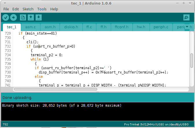
All those functions took almost all the FLASH memory
![]()
I have some 20 bytes of FLASH left. As a first demo, I uploaded video of pavapro resurrecting brain-dead Arduino.
In next project log, I'll cover the firmware of pavapro in more detail.
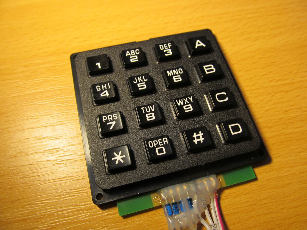
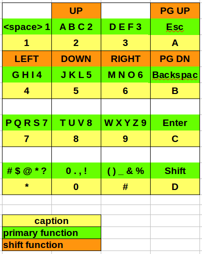
The keyboard in pavapro has this layout:
![]()
Pinout of the two 6-pin connectors can be seen from schematics (one of them is standard AVR ISP 6-pin connector). Pavapro was tested on both 3,3V and 5V targets. For various AVR-, you need to change program page size. I wrote more about page size parameter this log. It is sinle parameter, found under "Settings" entry. You can change it to 16, 32 or 64 bytes, as indicated by 10, 20 or 40 hexadecimal number.
Pavapro was tested on ATtiny2313 and ATmega328p MCUs, though it should work on most of the 8-bit AVR devices with FLASH under 64kB, except of ATtiny10 and similar - those have different programming interface, as well as X-mega devices.
-
Final hardware running
01/01/2015 at 20:10 • 0 commentsYesterday I soldered the PCB and today I flashed the firmware, previously developed on the experimenter’s board:
![]()
Except of single hardware difference (I ordered PCF8574 instead of PCF8574A - easily to workaround by two #define lines) it ran on the first try.
![]()
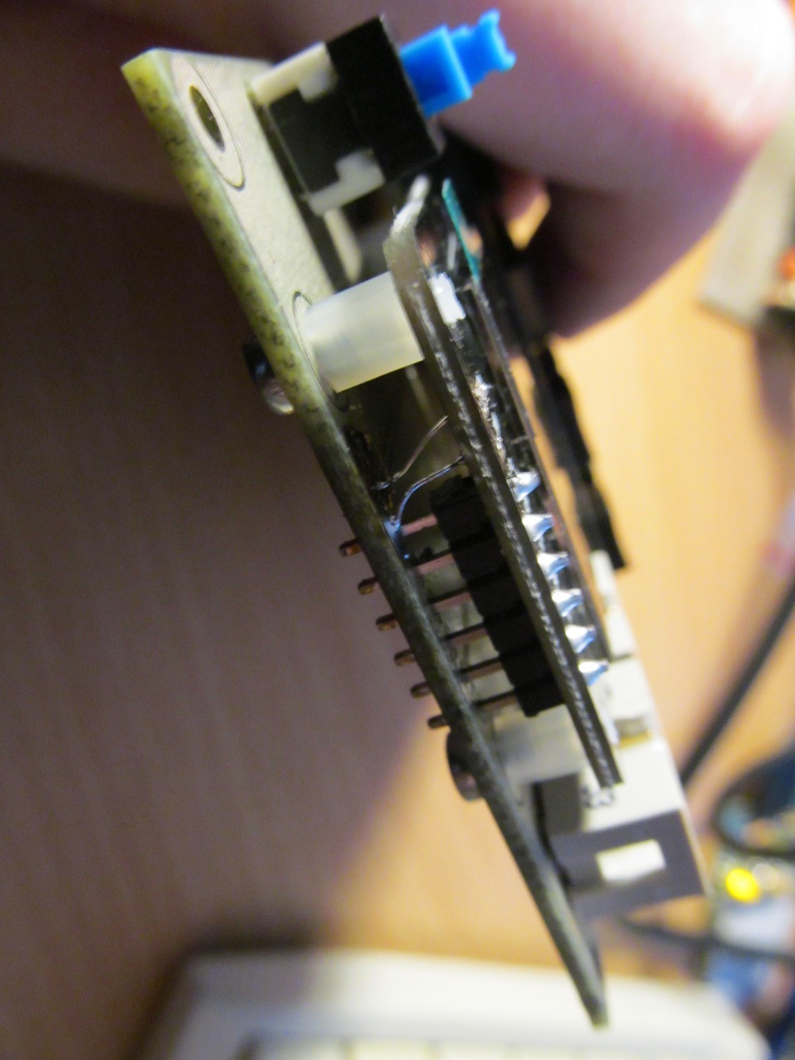
Needless to say, I made a few mistakes on the board during the design (I mentioned missing pull-ups on I2C bus before, did I?). Probably the most serious one is GND and VCC pins swapped for the display. Fortunately, I spotted it before powering the board, though after the display was soldered in place. Probability of releasing the blue smoke from display controller would be quite high if unnoticed. To fix it, I made this ugly workaround:
![]()
Never mind, I'm adjusting the original design to fix the bugs, so if somebody would ever decide to replicate my design, it will be (hopefully) error-less.
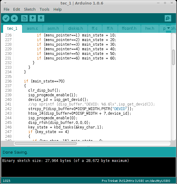
The current firmware allows to program FLASH and fuse bits of target MCU, edit text files on SD card and assemble AVR source files into binary (to be flashed with the on-board programmer) - I plan to film a short video demonstration. It grew pretty huge
![]()
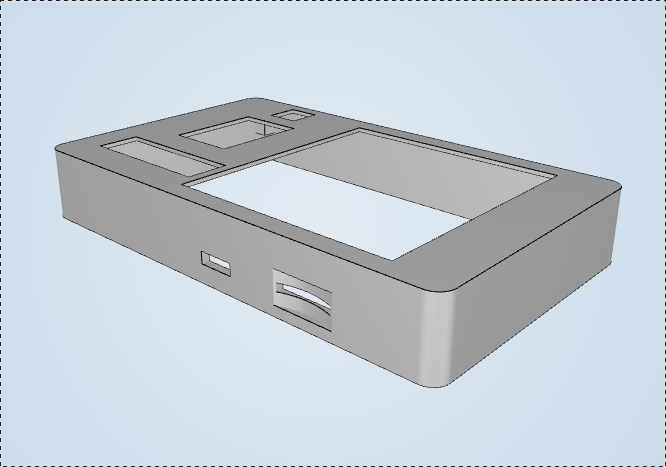
64kB trinket pro would be nice for this project. Currently I'm designing case for it and the first case revision is in the print, as I'm writing this.
![]()
It has round corners, lawsuit, anyone?
-
Switching on the soldering iron and a lot of pictures
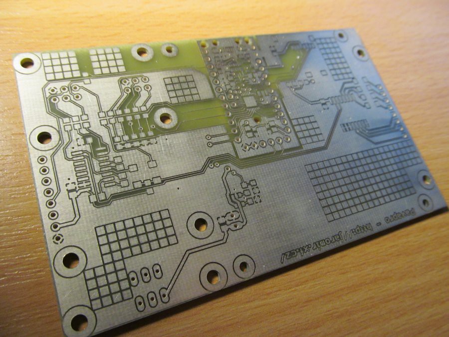
12/31/2014 at 13:04 • 0 commentsI received nice gift from fellow hacker yesterday - my nice, shiny, homemade PCB. Double sided PCB, with no soldermask, but I can live without it.
I didn't enjoy it very long, as I had a lot of work to do.
---------- more ----------
Soldering QFN AVR
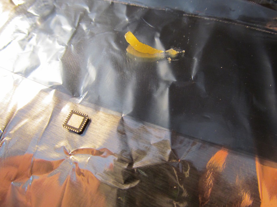
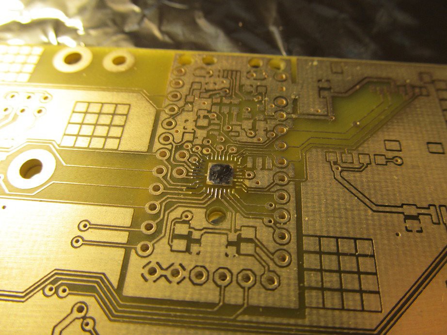
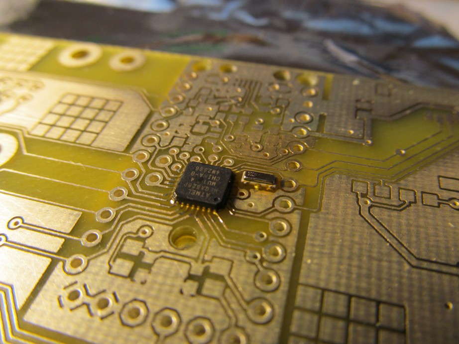
It is not that hard as it may look, even without professional tools. I took the AVR and bit of flux
![]()
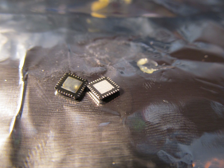
and solderer the pads. Notice the difference between soldered AVR (left) and virgin one (right).
![]()
I soldered the PCB as well
![]()
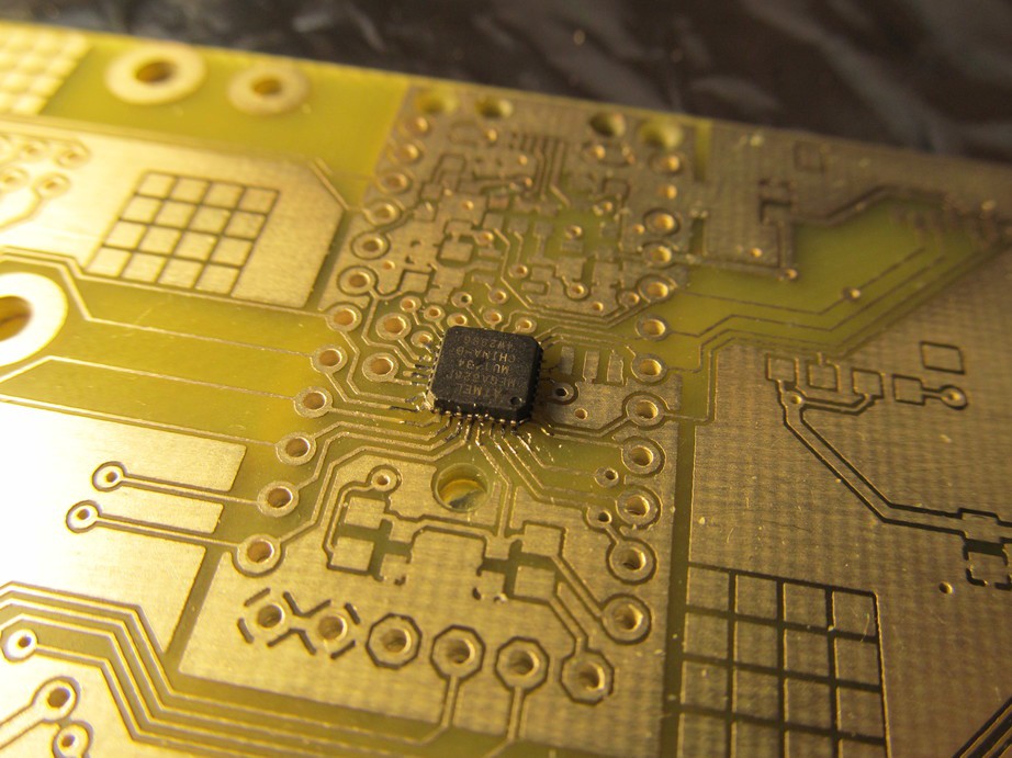
applied more flux to PCB and placed the chip on it.
![]()
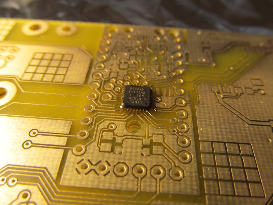
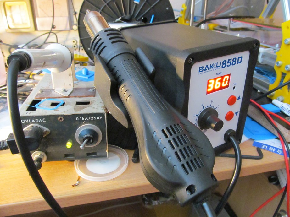
reflowed with hot-air gun and here we go:
![]()
Nicely soldered QFN chip, using those crude tools (homemade soldering iron on left, cheap chinese hot-air gun on right)
![]()
I repeated the same process for 12MHz resonator
![]()
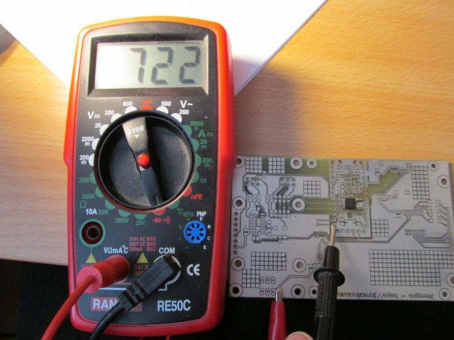
Then I took DMM and checked if the pads are correctly soldered. I checked the internal protection diodes on IO pins on diode check against ground
Yes, this one looks good. Approximately 600-800mV is fine. Supply pins do read lower values, something like 400-500mV. This way you can tell between short to ground (zero value), OK value or unconnected (unreflowed) pad (infinite value). Of course, this isn't complete test, but as first-round check it's OK.![]()
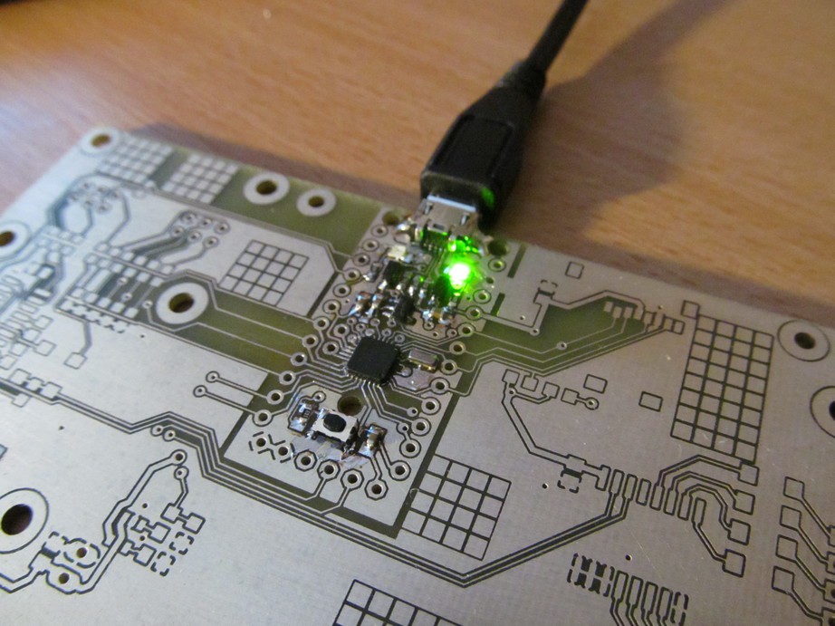
I soldered the other trinket pro components and made smoke test:
No blue smoke released, so far so good.![]()
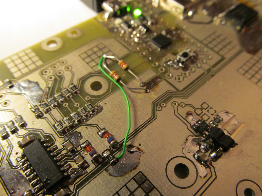
As I populated other components, I noticed I forgot to add pull-ups on I2C bus. D'oh! I greenwired (literally) the pull-up resistors and made the use for "breadboard" areas I included on the PCB.
Another smoke test, all voltages do look reasonable.![]()
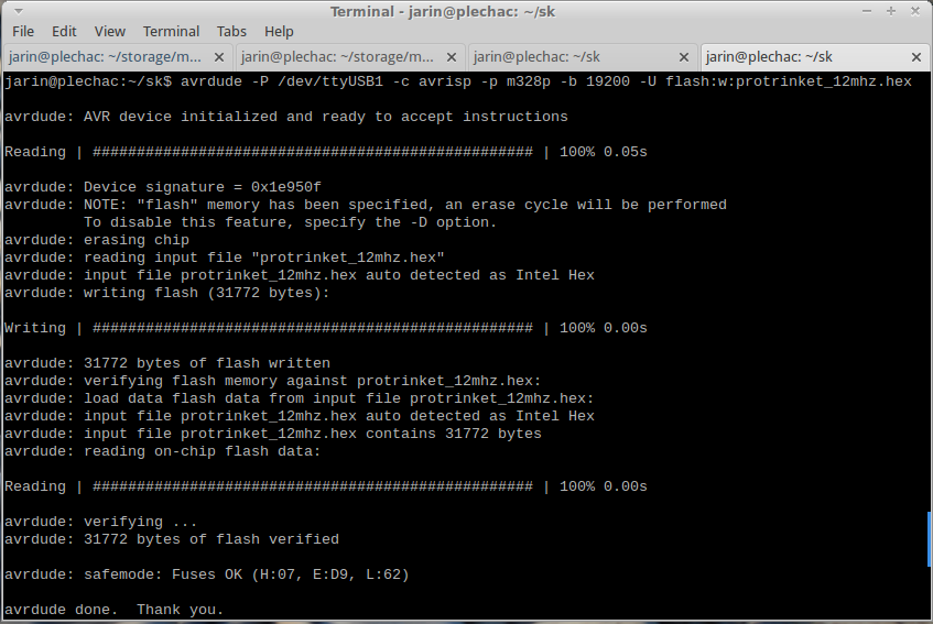
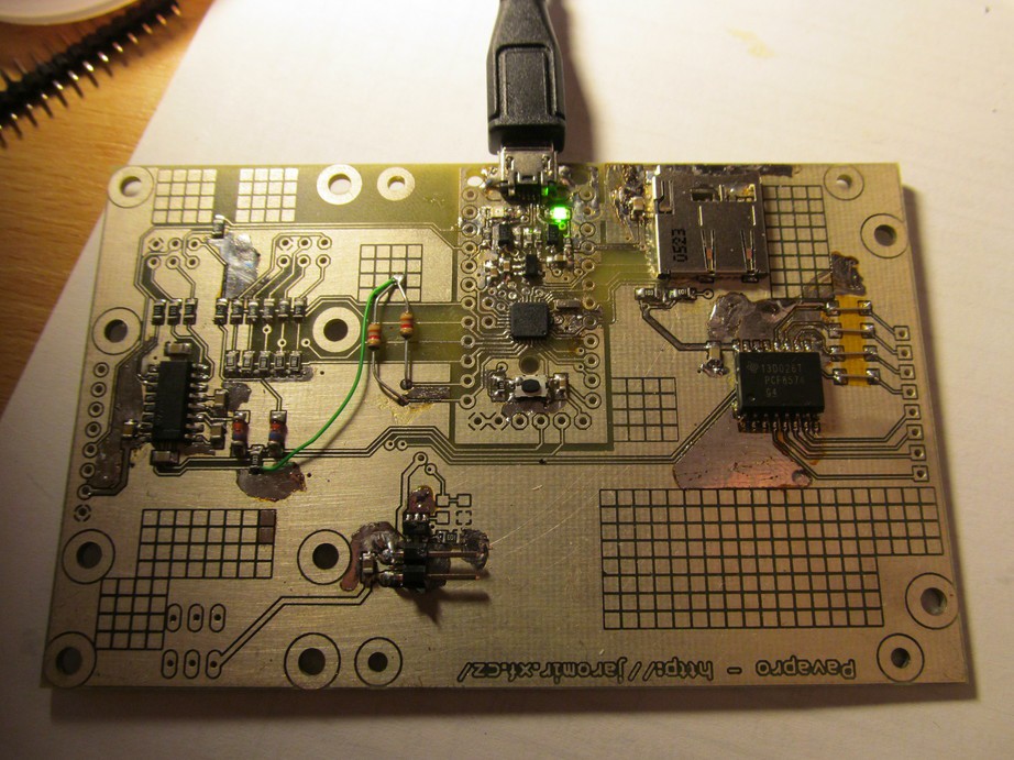
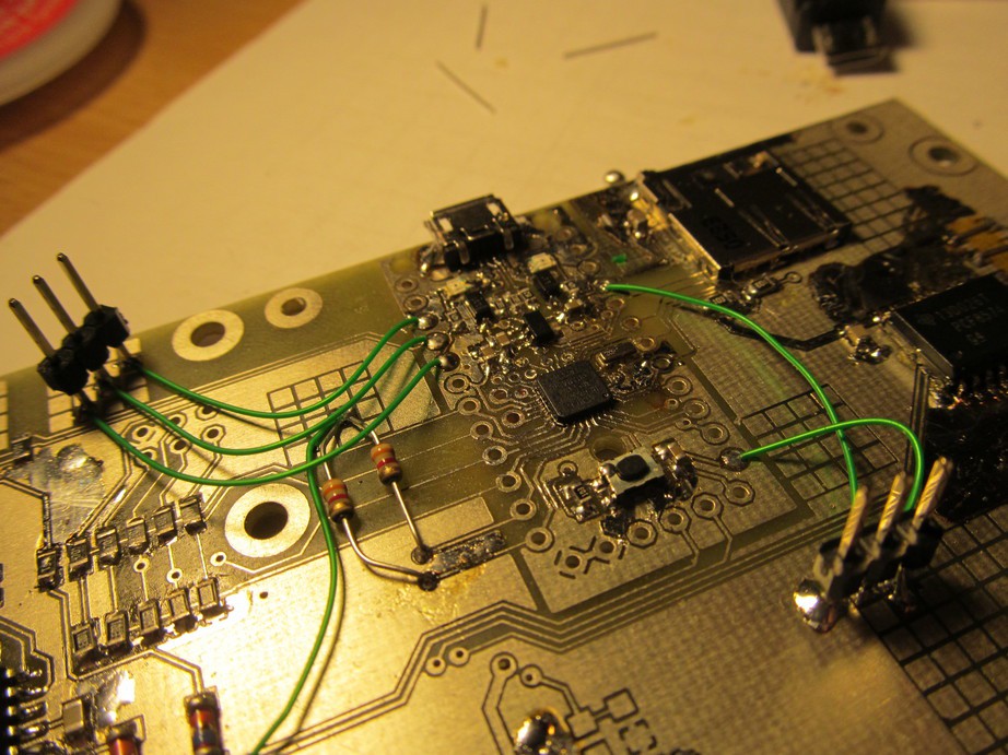
Now, the FLASH memory of AVR is empty, as expected. I need to get the trinket bootloader into the chip, somehow. For this purpose I used the "breadboard" area again and soldered pin headers for all ISP signals.![]()
![]() I flashed the bootloader (for testing purposes, I took another arduino, flashed arduino ISP sketch and with a little help of avrdude I flashed the bootloader in.
I flashed the bootloader (for testing purposes, I took another arduino, flashed arduino ISP sketch and with a little help of avrdude I flashed the bootloader in.
And then, I flashed fuses and the ATmega328p on the board went alive as trinket pro![]()
![]()
Whoo-hoo!
Using the manual from adafruit I set up the arduino IDE for trinket pro and flashed blinky example
![]()
Awesome! it works!
Now I'm going to port the software from my protoboard version of pavapro
![]()
-
Keyboard works, target AVR programmed
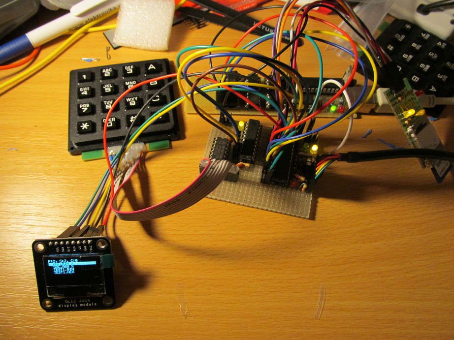
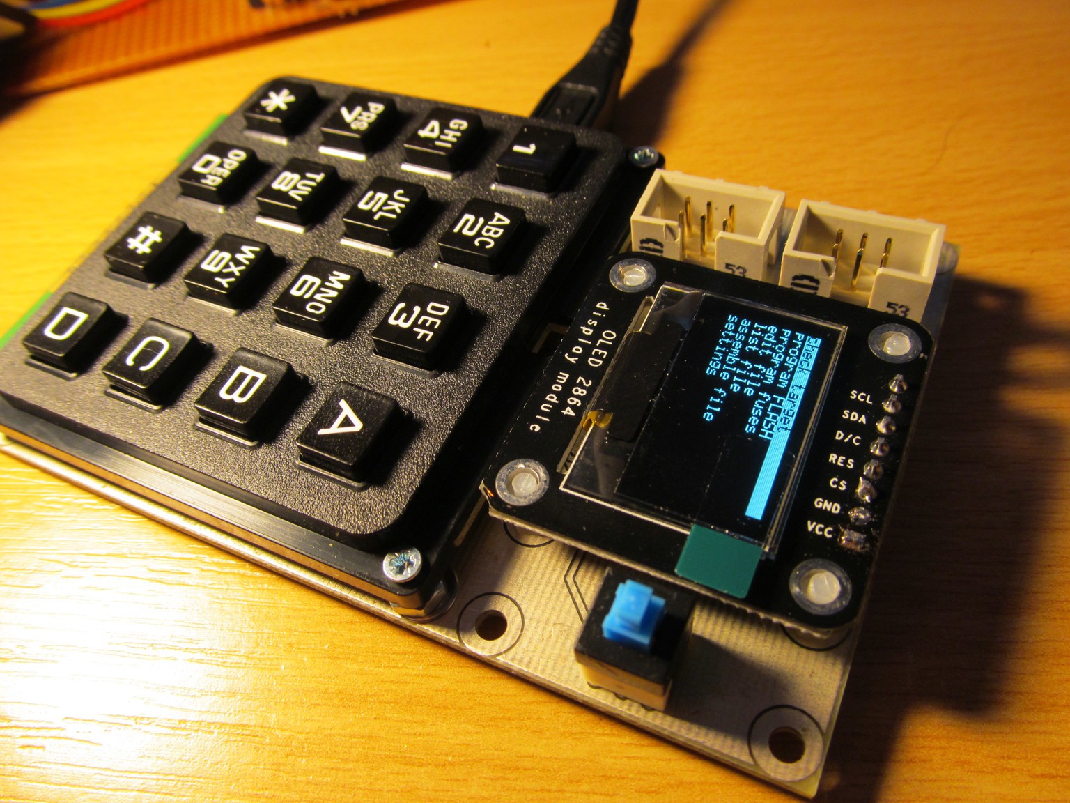
12/28/2014 at 13:06 • 0 commentsWhen doing some bigger projects - like this one - I like to build it in blocks, test each one separately and then, when everything seems to be OK, connect it together. Sometimes I use one block to test some other. So I made OLED display running and used it to debug SD card connection and FAT filesystem. Now, as I started to work on AVR ISP programming routines, I decided to connect keyboard first and make it running.The keyboard is simple 4x4 matrix keyboard, I bought it locally, though it looks like quite generic 4x4 telephone type keyboard.
It occupies all 8 IO lines of PCF8574 I2C port expander and the algorithm for reading the keyboard state is quite simple, actually and described many times before. For now, I setup the keyboard routine to read the keyboard state and return keypad number, this is enough to serve as simple user input for debugging purposes. Let's move on.
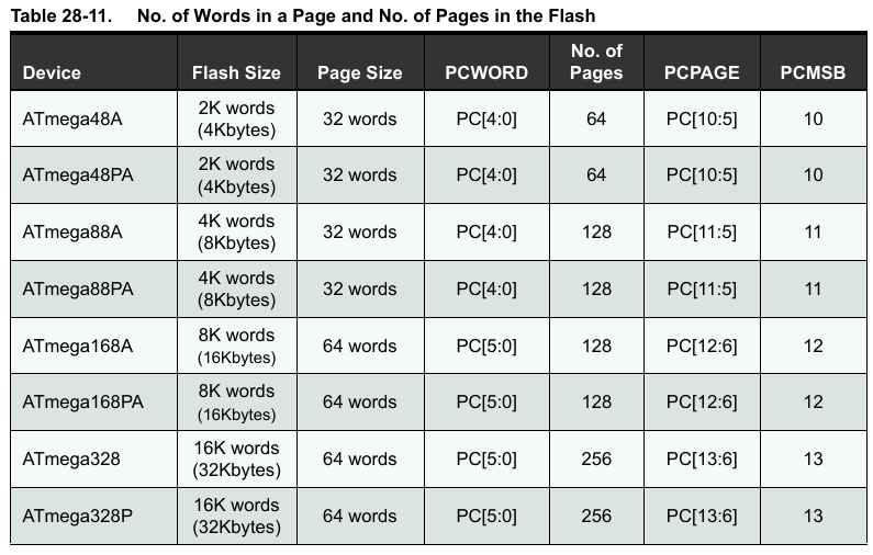
As I wrote before, the target AVR is connected and responds to simple ISP commands, giving me hope to finish the programming routines soon. Programming of AVR FLASH is done on page basis, where you must load the FLASH data into page buffer first and just then issue command to write this buffer into FLASH. The only complication is that page size is different for different AVR types (probably because of FLASH internal organization) - and because I want to support the ATtiny2313, ATtiny85 and ATmega328 at least, I have to make the page size switchable.
![]()
Page size table for ATmega88/168/328
![]()
Page size table for ATtiny25/45/85
Page size for ATtiny2313![]()
Basically, it looks like the programmer should support at least 16-64 words (each two bytes) long pages. No big deal, but fixed size page would be nice.
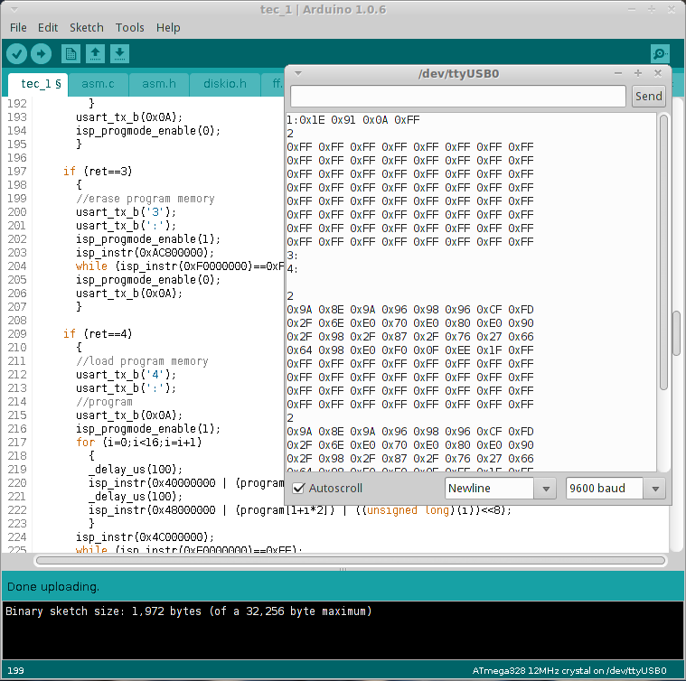
To test the programming algorithm, I wrote simple software, exercised by key presses, with result fed to serial terminal. Number one started device ID check, number two read first 16 words of FLASH memory, number 3 erased the whole FLASH and key A started programming of FLASH with simple binary to blink a LED. The binary is hand-assembled and temporarily stored in arduino FLASH
sbi 0x11, 0x6 ;clear DDRD, bit 6
sbi 0x12, 0x6 ;turn LED off
cbi 0x12, 0x6 ;turn LED on
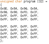
rjmp PC-0x2 ;jump up, to turn LED offThis should turn LED on and off - probably not to see with naked eye, but oscilloscope or logic analyzer should show it. The source results in this simple 8-byte machine code
![]()
stored temporarily in arduino FLASH. For now, I'm not messing with reading the binary from SD card, I'll implement this later, once the AVR ISP routines will be debugged.
Well, integration of the newly programmed keyboard routines and AVR ISP FLASH programming works fine:
Not
Notice, the FLASH is empty after first "2" command (reading FLASH), but contains the binary after "3" (erase, not needed for empty FLASH, but anyway) and "4" (load FLASH) commands. Yay!![]()
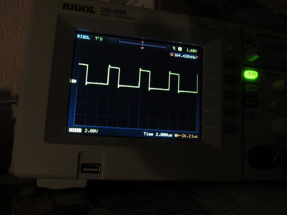
Oh yes, and the target ATtiny2313 does what I would expect. The LED on pin 11 (PD6) looks like just dimly shines, but oscilloscope shows fast squarewave on the pin:
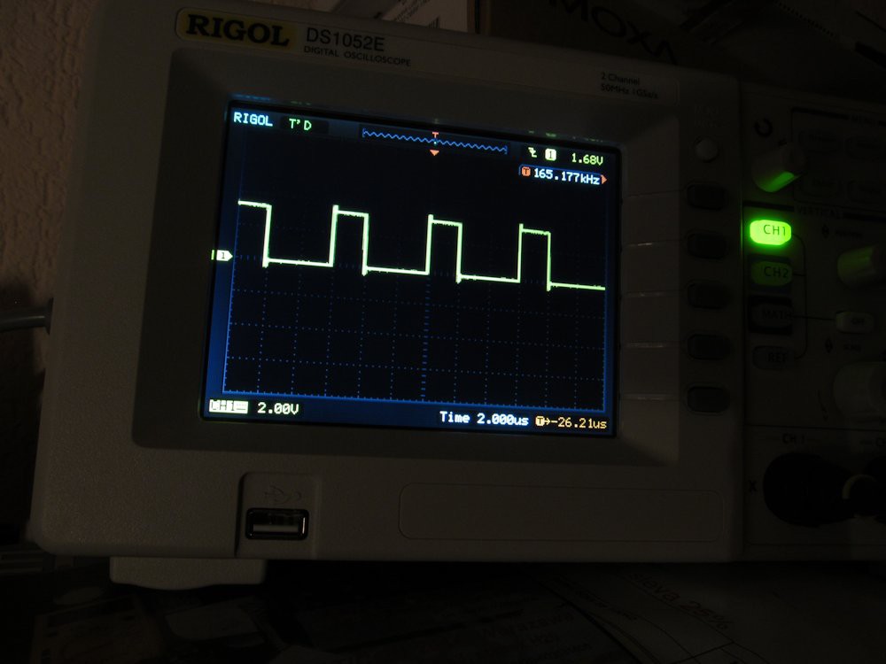
Because the sbi, cbi and rjmp instructions took two clock cycles (6 cycles for the complete loop) and the default clock is internal 8MHz RC oscillator, divided by 8 (resulting in 1MHz clock), I would expect something like 166,66kHz (1MHz/6) frequency. Scope shows 164kHz, what is quite nice and small deviation. The RC oscillator is temperature dependant, so I put my finger on the ATtiny2313 package for a few seconds:Approximately 0,5% shift. Bear this in mind next time you'll be designing something with internal RC oscillator of AVR MCU.
This is progress for last night, now I'm going to clean up the ISP FLASH programming routines and link it with SD card routines to get really usable programmer. Oh, it's 28th, time to finish the contest runs like crazy and I still have a lot of work.
-
Assembler assembling assembly sources
12/26/2014 at 13:40 • 0 commentsWhile I'm still waiting for my PCB, I did a bit of work on software. In fact, I should have done my high-level programmer routines, as the low-level ones already do work, but I was impatient enough to start to work on the AVR assembler.
The assembler isn't that complicated piece of software - in theory, at least. Just take a line like
LDI R25, 0x23
meaning for the CPU - take value 0x23 and put it into register R25. This meaning is not important for assembler, it just needs to translate this form - easy to understand for human brain - into machine code, actually being easy to understand for the silicon brain. The instruction set is probably in every datasheet, but deeper explanation, including binary opcodes is in separate document. By the way, machine code for this instruction is:
1110 0010 1001 0011
Simple enough, huh? In fact, you could write all your software in machine code, but humans tend to be less error-prone when writing in assembly language, or better in higher-level languages, but we will ignore those for the time being. Running AVR assembler on AVR is just about the right task.
The assembler needs to read source file line by line, determine whether the line seems to be valid instruction (in this case LDI), read operands (in this case R25 and 0x23) and create correct bit pattern of machine code. Unfortunately, the machine code patterns are quite different between instructions and some instructions do have two operands, some just one and lot of them have no operands. As usual, this is the detail that makes assembler complicated, not mentioning the assembler has no clue what the heck is "R25" and it needs to substitute it with proper register number.
Side note regarding C code writing and debugging
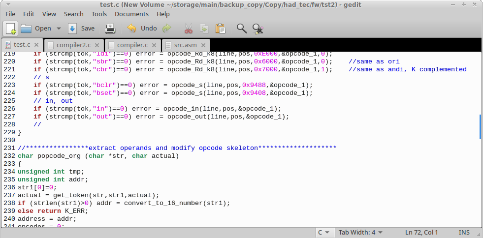
For this purpose, I put arduino IDE away and decided to write and debug vital assembler parts in plain C using C compiler of my PC workstation, to be transferred later into arduino IDE. As Linux has inherent support for this development, I used GCC and Gedit editor. It is not that complicated and described countless times in tutorials, like this one.
![]()
Notice the editor. Pure joy, compared to arduino IDE.
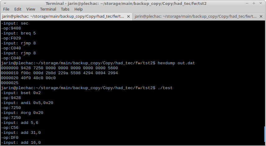
Together with xfce terminal (I'm using Ubuntu with XFCE desktop) it makes simple, but powerful development combo, allowing much faster edit/compile cycle and easier debugging via console messages, compared to arduino.
![]()
Terminal window, with debug messages.
End of side note regarding C code writing and debugging
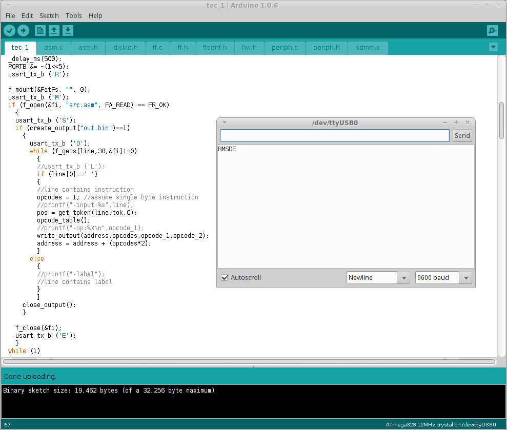
The assembler now counts around 600 lines of C sources and takes approx. 6kB of FLASH memory. Along with he fatfs and display routines, the total FLASH requirement is around 19kB. So far so good, I have 9kB of FLASH left, for editor and high-level programmer routines. RAM footprint is quite low, around 60 bytes, but the assembler needs to read and write input/output files. Fortunately, fatfs overhead is quite low, so now I'm using less than half of available (2kB) RAM. And this is how it looks, running on real AVR
![]()
I'm using serial port and arduino built-in serial monitor to display debug messages. R stands for 'run', meaning running program, M means that filesystem was mounted, S - source file is open, D - destination file is open too and finally E - program reached its end. There was lag a few tens of miliseconds between D and E, meaning intense data crunching inside the AVR.
Oh yes, and I updated my github repo for this project.
Pavapro - portable AVR programmer
Pavapro is tiny programmer you can bring anywhere. You can load binary file into it and bring/use it as you wish. And a bit more than that.
 jaromir.sukuba
 I flashed the bootloader (for testing purposes, I took another arduino, flashed