Background
I saw [Daniel Rojas]'s LED matrix-based micro word clock the other day, and thought it was a neat idea. Then I realized I had such an LED matrix, which I'd bought at a local electronics store a few weeks ago for no particular reason. I was originally thinking of using an MSP430 for low power consumption, but there are no MSP430 devkits small enough to mount on one's wrist, so prototyping would be difficult. At this point I realized that because I had to pick a different controller anyway, I might as well enter the Trinket EDC contest.
The layout of the letters will eventually be generated by a genetic algorithm technique, like this. [Alessio] said he couldn't find any grids smaller than 11×11 (for English), but he didn't allow breaks in words like [Daniel] did. Before I get that done, I'll use a version of [Daniel]'s grid, modified to have +1, +2, +3, and +4 indicators for one-minute resolution. With those indicators, this will be the first word clock that I'm aware of to display the time to the minute, not rounded the closest five minutes.
Initial thoughts on design
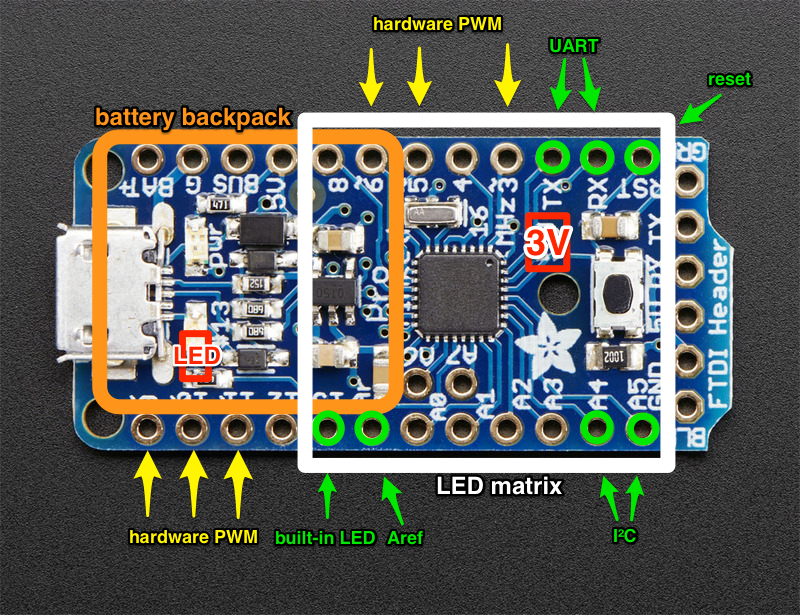
The Pro Trinket has only 18 GPIO pins, and I need 16 for the LED matrix. This makes pin allocation a bit tight. Furthermore, the Trinket doesn't have 16 GPIOs arranged in two opposite rows of eight. On one side it has seven, and on the other side it has eleven broken into a group of seven and a group of four by the Aref pin in the middle. Furthermore, some of those pins have secondary assignments—UART, I²C, and the built-in LED. I will have to figure out how to connect the LED matrix to avoid conflicts. I'm planning to use the built-in LED as a low-battery indicator, so I don't want it lighting up as the matrix is scanned. If I end up soldering the matrix directly to the Trinket, I'll insulate or shorten the pins I don't want connected, and wire them elsewhere.

(Note that I made this diagram based on the 5 V Pro Trinket, and Skitch won't let me replace the base image without having to redo all of the annotations, so I've corrected the differences that matter in red: the voltage label and the exact location of the pin 13 LED.)
Expect a project log in the coming days with tentative solutions to these problems, as well as a 3D mockup of the assembly (hopefully).
However, I expect the electrical design to be one of the easier aspects of this project. I expect miniaturization and generating the word clock grid will be quite a bit harder.
Also, in the interest of miniaturization, I don't plan to include a real-time clock chip. Instead, I will use the Trinket's AVR to keep time. Based on its datasheet [PDF] (see Fig. 31-333, p. 493 and Fig. 31-338, p. 495), I'm estimating it will consume an average current of ~2 mA, which will result in ~75-hour battery life using a 150 mAh battery. Time will be set via UART initially, and by the gesture sensor later.
 PointyOintment


It'll be fun to see this thing strapped to your wrist. As far as the AVR keeping time, I think you can measure the system clock by toggling a pin and then account for deviation based on that measurement to get better accuracy.
Also, as a future challenge you could try adding an external 32.768 kHz clock crystal (I'm pretty sure the 328 supports that option) just to drive the internal RTC measurements.