-
Module layout proposal
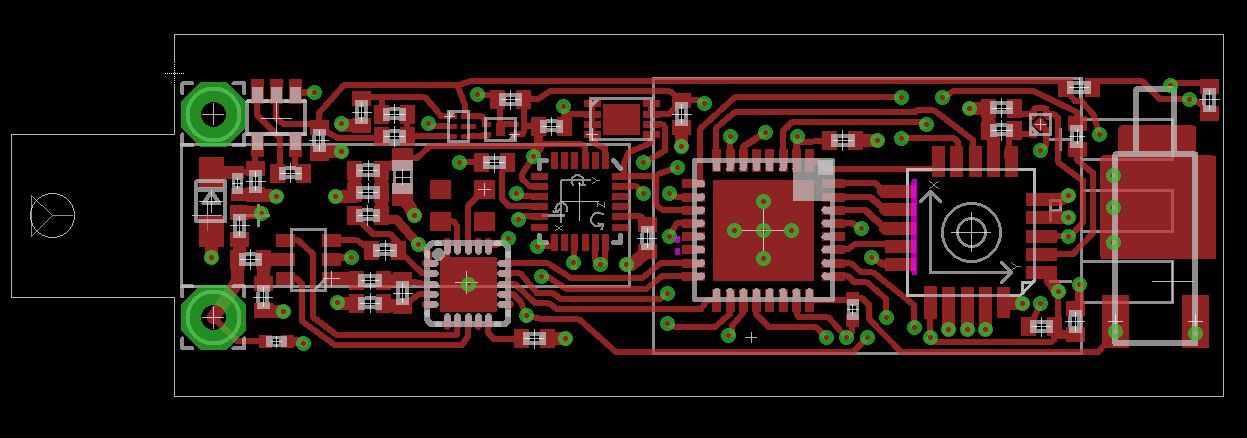
02/11/2016 at 14:36 • 4 commentsProposal for the module board:
Modules are arranged in a 2x2x5 matrix = 20 modules in a single PocketQub
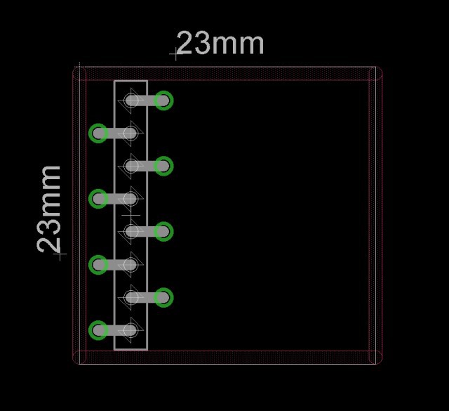
Eight long pinheads go up through the five modules of each quadrant.
Here is a picture of the proposed pinheader,
Five pins are unique UARTs (halfduplex) for each of the five modules in one column, additionally a +3V3 and a GND pin.
I planned a unique power latching for each module, but this would require additional five pins. Instead, there might be a latching for each column, and to prevent other modules of this column to be shorted by another module, I´d suggest to use a polyfuse on each module mandatory.Let me know if you got a better idea to arrange/connect the modules which saves more space.
NOTE: I don´t want a bus system, because I want to avoid unnessecery coordination between the modules´ owners and avoid a bus failure if one module shorts the bus.

-
Own Hardware in space
02/07/2016 at 12:37 • 0 commentsA motivation check:
------------------------------
I though about enabling people to put their OWN hardware into a pocketqub. To get a good launch price, the hardware would need to stay inside the pocketqub -but could last for several years in space.
There would fit 20-24 modules inside about a square inch each. It would be possible to provide openings in the outer shell for optical/radiation or other sensors for each module.
I would provide a standard UART to each module. The data would be sent via SSTV picture. Each module would get a dedicated area in that picture.
Tell me what you think about that?
With 20 modules inside, the launch cost would be around 1000$ per person.
I would take care of the carrier module, the power system including solar cells, charging overcurrent/short circuit protection, the radio system/antenna deployment, the UART router, in-orbit stabilization, all the flight approval tests and the paper war etc.
There would be a PCB template with a pinheader for the connections and a simulator for easy development.
Like mentioned, the Interface would be a standard UART. Maybe a possibility to share data with other modules would be cool.
I will make the pocketqub ready for launch if there are enough people (at least 20) to build their own module and share the launch costs. -
SSTV working
04/07/2015 at 18:24 • 0 commentsFirst SSTV picture from the chipstar. Resolution is 40px*30px.
It´s sent in standard BW8 format. Only 30 lines are sent - one line contains 120 pixels representing 40 blue/green/red pixels each.
Now I am working on a converter to melt them together into a RGB image.
Transmission time is two seconds on a standard audio line.It´s funny: Just holding the handheld radio in front of the PC microphone is enough to receive that picture within 2 seconds
-
Reaction Wheel
03/31/2015 at 20:36 • 1 commentA big change occured in the new board: Instead of three coils there will be one permanent magnet to align the satellite to the earth´s magnetic field.
This will have the advantage of detumbling and stabililzing the satellite.
The remaining axis can be controlled by a reaction wheel (mounted on the right side).
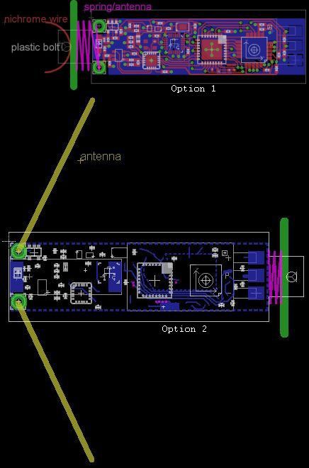
It´s basically a small motor which changes the rotation around the mounted axis. This axis is perpendicular to the two others magnetically stabilized axes, so you can change the camera´s perpective instantly while maintaining attitude stability.
Board is going in production asap.
-
Board design with RGB camera
03/30/2015 at 17:36 • 0 comments -
Imager update
03/25/2015 at 20:50 • 0 commentsPlayed around with the lowres imager IC - too slow for a reasonable use.
I will change it to a 640x480 camera. The problem of this cam is the availabilty. I ordered some stock and will stock up for the future use, at least to have enough for the devkits and the launch.
The good news: This camera is already part of the TRSI-Sat, so the TRSI.-Sat will melt into the CHIPSTAR. The code is already working, so the change will be a quite easy task - there will be just some delay.
-
Imager ICs arrived
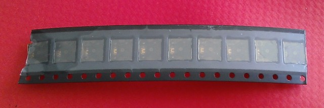
03/24/2015 at 10:11 • 0 comments -
Project Fusion
03/17/2015 at 20:29 • 0 commentsMaintaining two project for the same launch was not efficient :)
I deleted the TRSI Deployer satellite as it will be a part of the CHIPSTAR project.
There were also not many news in the last weeks. The reason is that I am waiting for the imager ICs from China. They aren´t available in Europe at this time.
-
Entered the Hackaday Prize
03/15/2015 at 02:20 • 0 commentsI submitted the project for the Hackaday Prize 2015.
But what exactly can a tiny satellite do for the community?
The CHIPSTAR is a platform - what it´s used for is up to you - you can program it and come up with a concept that may be beneficial for all of us.
Here is one idea:
Free communication network: 4 billion people in the world are offline. A satellite network could be a great solution to provide free worldwide communication. Use the CHIPSTAR to develop communication protocols, stationkeeping, intercommunication, routing etc.
Another point is the accesibility of space launches to a wide range of enthusiasts:
The costs for a cubesat launch are about 100.000$, a PocketQub reduces them to 30.000$.
We are trying tu push them down to 1500$ - for one CHIPSTAR, and of course we hope for fundings to make a first launch possible. -
Milling the Deployer
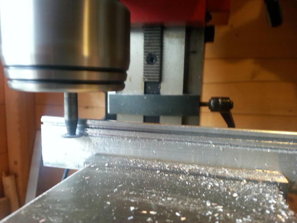
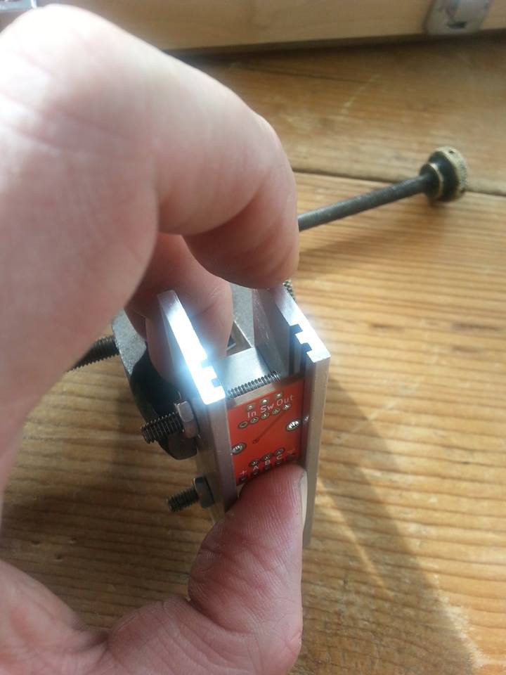
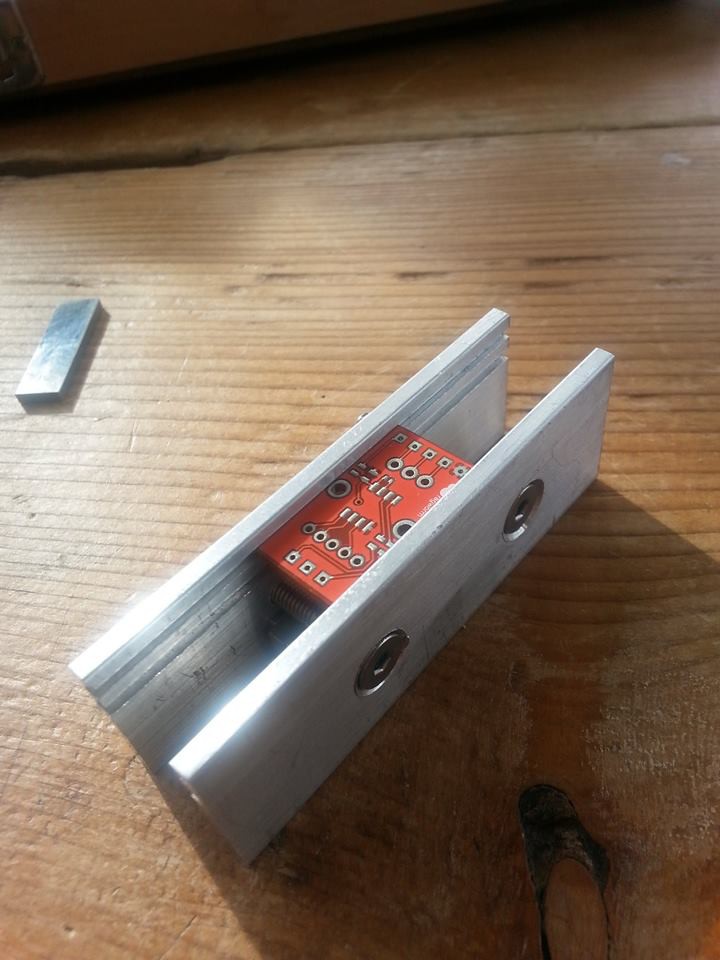
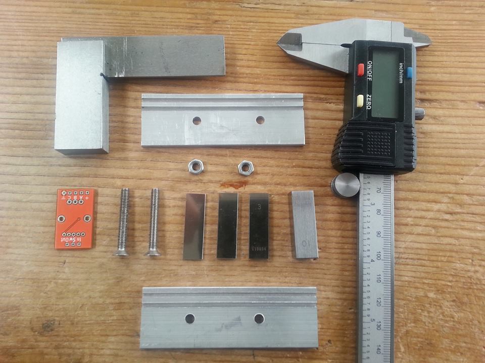
03/08/2015 at 15:53 • 0 commentsJO HINCHLIFFE (Concretedog) was working on the deployer test rig.
--- quote JO HINCHLIFFE ---
Been working today on a test rig to help determine the rail sizes that will hold the chipstars and that the chipstars will be pushed out of in the deployer. So it started by milling two 2mm wide slots into two pieces of aluminium at the two different depths I was testing, namely 1mm depth and 1.5mm (+-0.02). I then drilled and countersunk the matched pair of railplates and then, using some A+ inspection slip gauges to vary the height and some clamps to keep parallel, test different distances between the plates.
It seems that either depth holds the PCB securely (note this isn't a chipstar PCB just a PCB I had left from another project) and if parallel a gap/tolerance of 0.3mm gives a free slide yet still has plenty of rail wall holding the PC at any given point.
--- /quote ---
 Paul Kocyla