davish
-
Final Touches
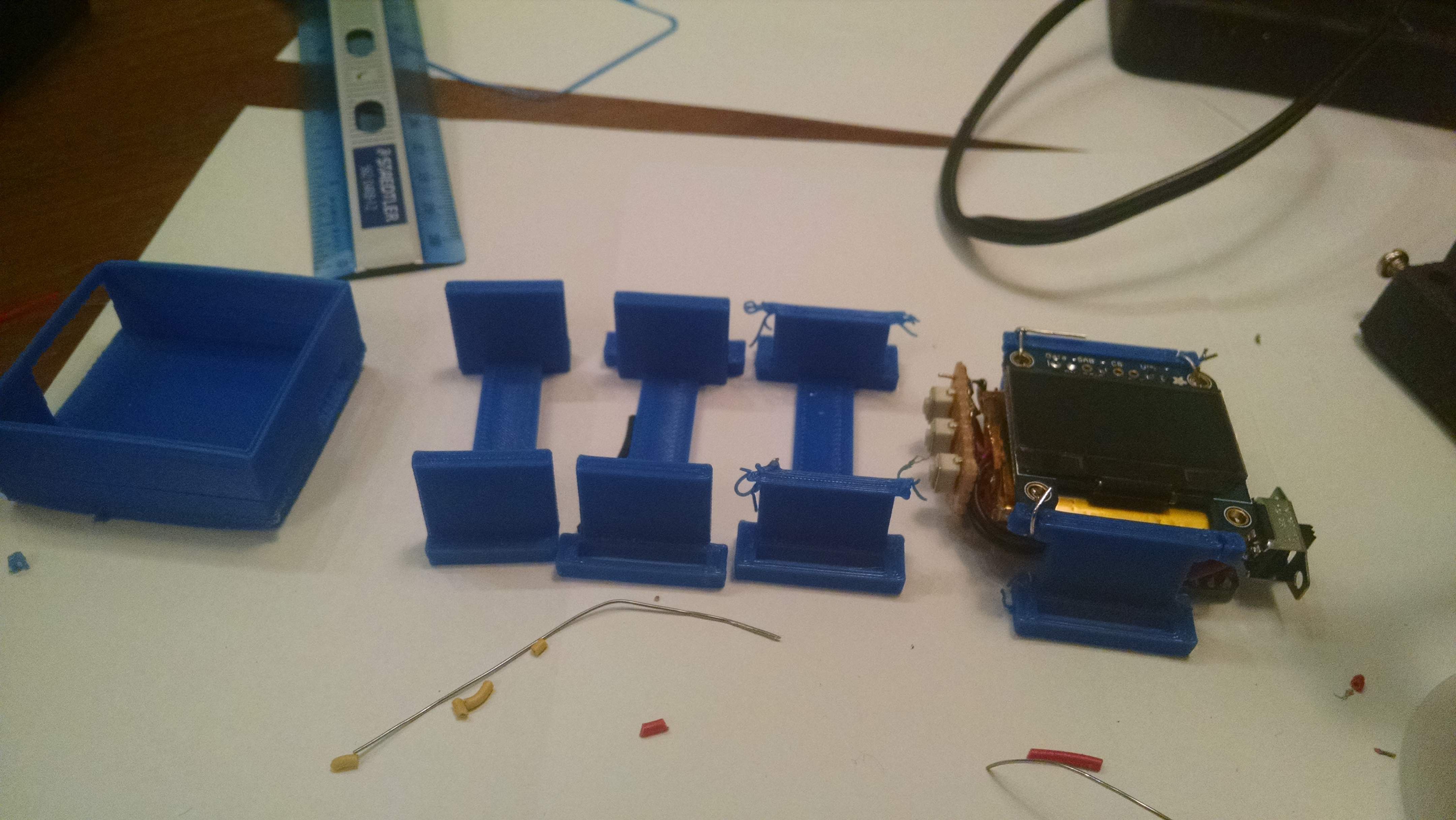
01/03/2015 at 00:04 • 0 commentsWith everything electronically on the watch complete, today I added a much-needed power-switch and made a case. I went through a few iterations of that. First, I tried just making a box around the watch, but that was too bulky, and didn't let any of the hackiness of the watch show. So, I opted for a much more barebones design that doesn't protect the watch very much, but shows off the insides. The progression goes from left to right:
![]()
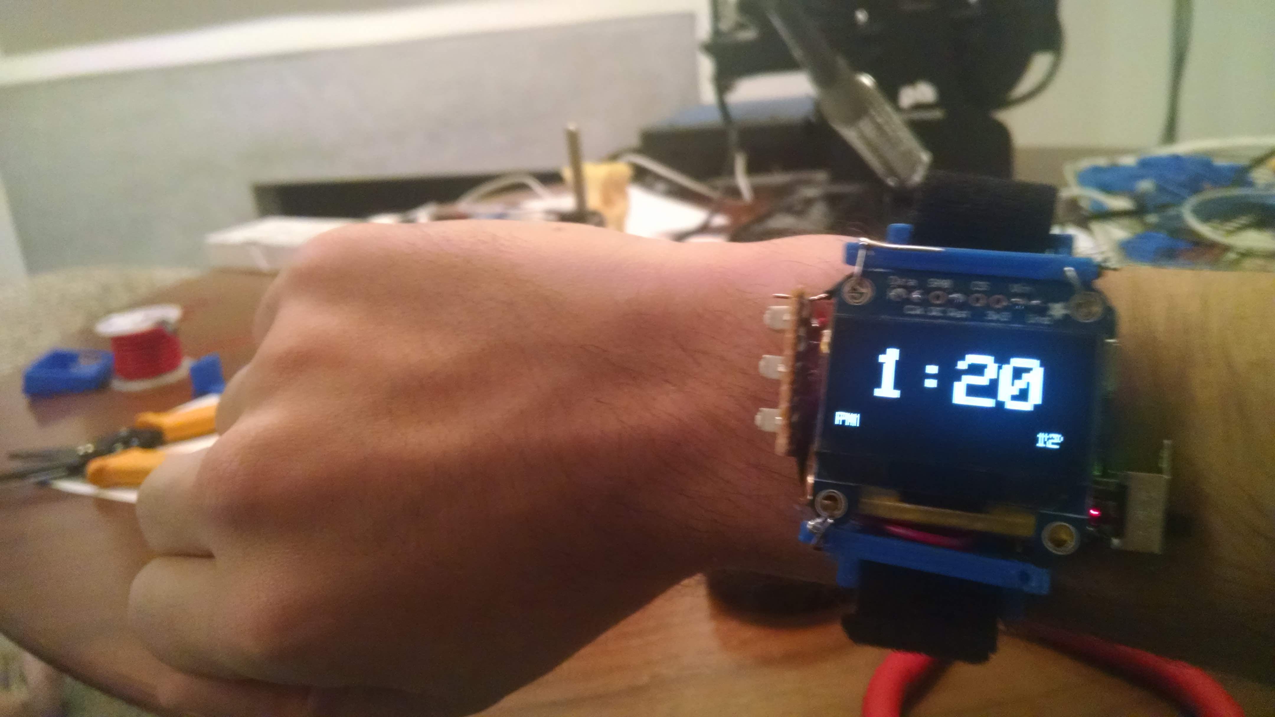
You can see the final watch all the way on the right, but here's a close-up, on my wrist:
![]()
Now that the watch is done, the next (and last) thing to do is film the demo video!
-
Putting it all together
12/30/2014 at 03:53 • 0 commentsInstead of waiting for the step-up regulator to arrive, I decided to put everything else together in a small package. First thing I did was cut down the leads on the OLED. Then, I soldered the SDA and SCL wires to A4 and A5, respectively. The reset pin was switched from 4 to 12, since 4 was on the other side of the trinket. I soldered Vin to pin 11 and Ground to pin 10. In the code, 11 is set to OUTPUT, HIGH and 10 is set to OUTPUT, LOW. This way, the wires don't have to stretch all the way across the board. After that, I soldered the backpack back on.
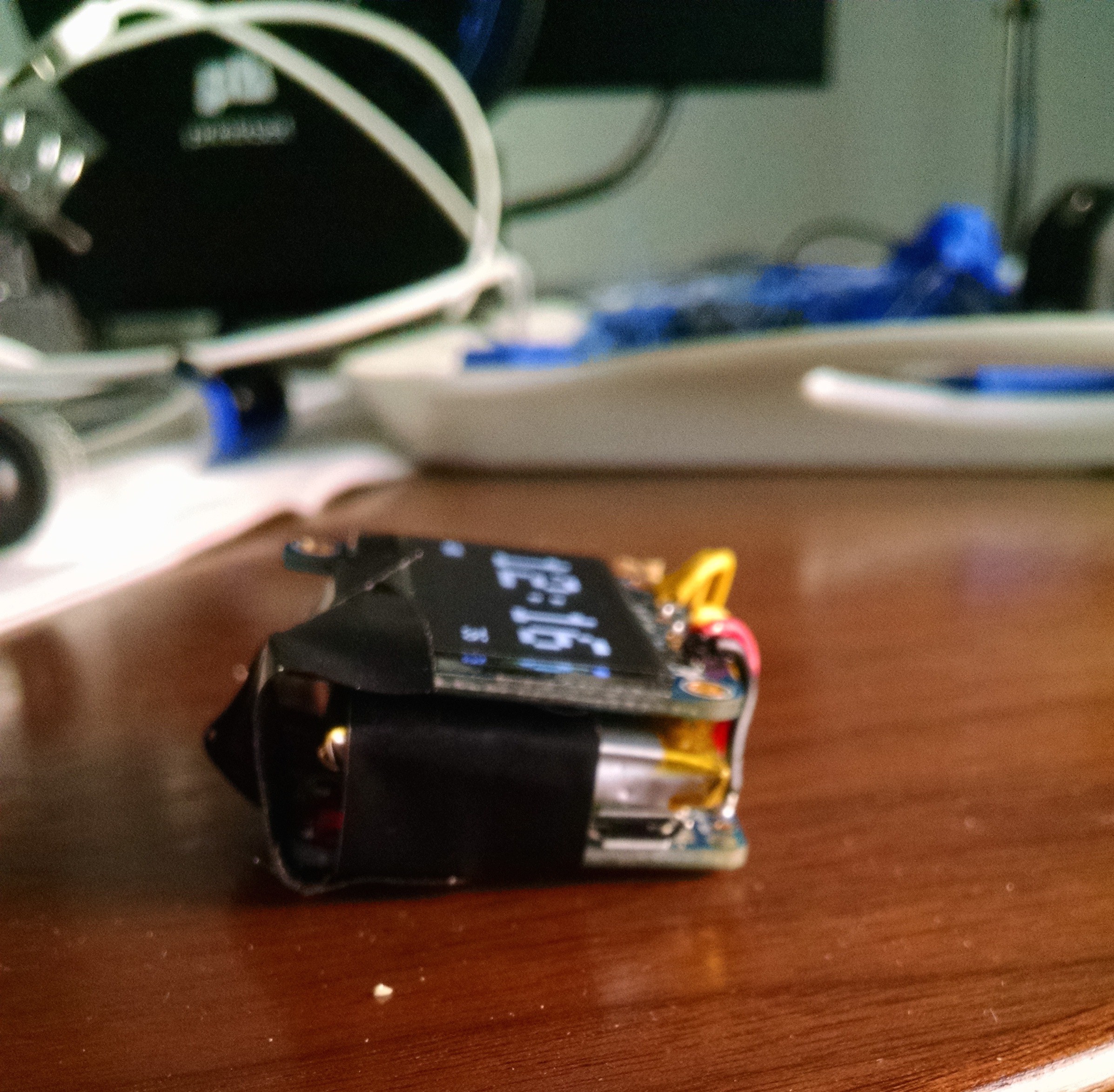
The next thing to do was to solder on the buttons. I placed them on some PCB from RadioShack (I know, I know), and soldered them in. I then cut off the extra board so it would be less than height of the watch, and then soldered leads for the three digital pins to the other side of the switches. After soldering that all together, soldering the ground lead, and bending the wires to "smush" everything together, I had something that resembled a watch:
![]()
Since the RTC currently isn't integrated, the next thing was to find a way to set the time. C++ adds a string constant, __TIME__, that represents the time in HH:MM:SS format. I parse this string, and set the hours, minutes and seconds to the right value. I wrote a function, adjustInternalTime(), that increments milliseconds using millis() and increments seconds, minutes, and hours accordingly. The last thing I added was a new mode for changing the time. It looks pretty similar to the digital clock view, but it's in 24-hour mode and tells you if you're incrementing hours or minutes. A video, showing off the new form factor as well as an overview of the software as it stands, is below:
Next thing to do is to make an enclosure and watch strap. This'll be a little tricky since it can't be too bulky.
-
From Uno to Trinket: Some Problems
12/26/2014 at 05:23 • 0 commentsNow that all the parts are proven to work on the Uno, it was time to move it all over to the 3.3V trinket. The screen and buttons worked perfectly fine, but it turns out that even though the DS1307 RTC works fine with 3.3V on its I2C pins, it still needs 5V input voltage; hooking it up to 3.3V just gives a random date that doesn't change. It doesn't seem like there's a way to get around this, so I've ordered a 5V step-up regulator from Pololu. Hopefully, that'll trick the RTC into behaving properly. While I'm waiting for that to arrive sometime next week, I'll be working on a case to be 3D-Printed, and refining some of the code.
-
Real Time!
12/26/2014 at 05:19 • 0 commentsI started off today by soldering together the DS1307 RTC kit and hooking it up to the Uno. After running the example program that sets the time, I wrote a function called updateTime() that takes the place of demo(), but hands off the actual time instead of the minutes looping over and over. This worked out fine, and as of now, the Trinket Watch was a functioning bedside clock! I also polished off my stopwatch mode, which works just fine. Video below, with some more Pong as well:
-
Back to the hardware
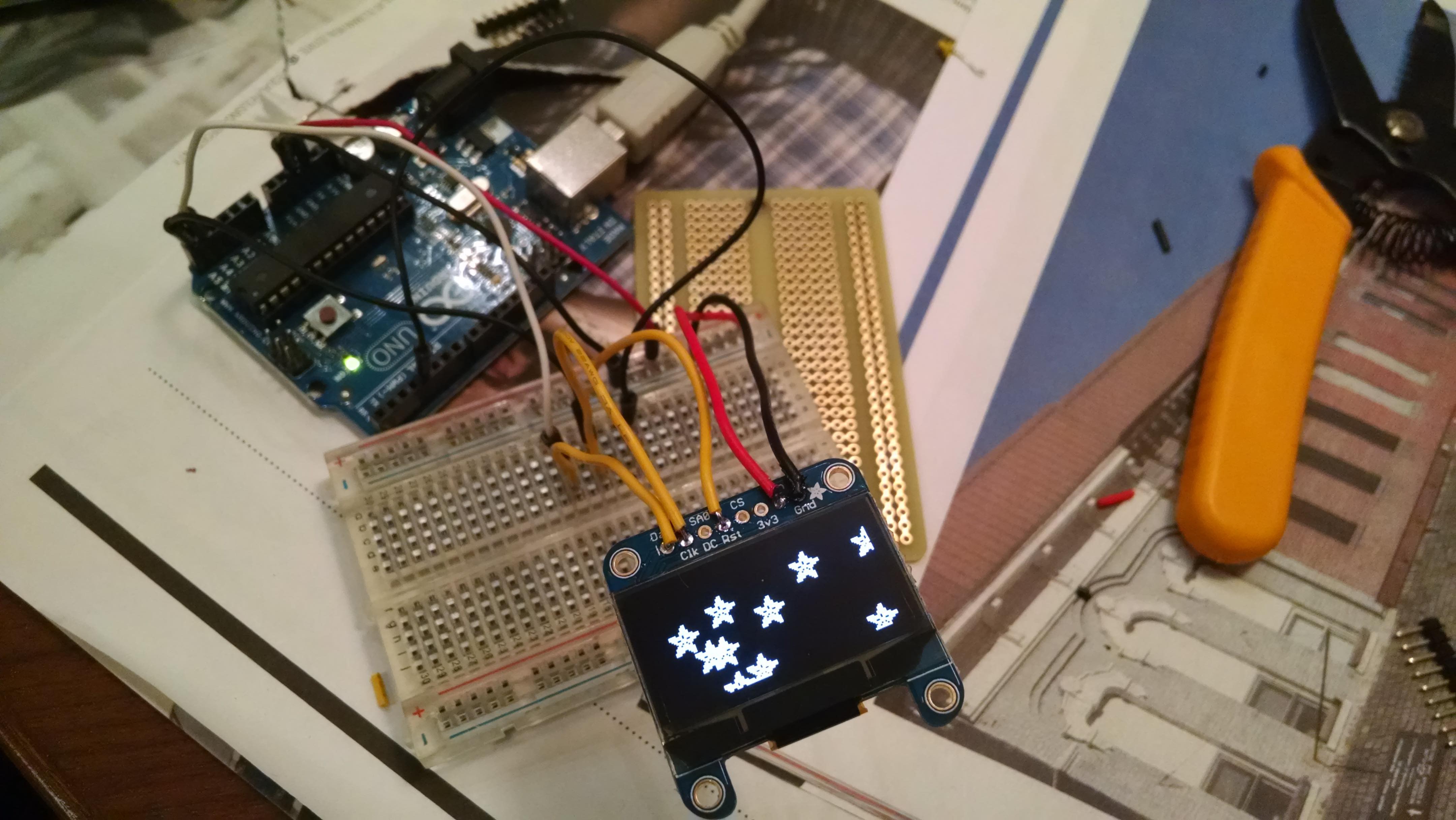
12/25/2014 at 05:10 • 0 commentsAfter a long day of traveling I come home, check Hackaday, and realize that I won the fourth drawing for the EDC contest! That definitely made my day. To follow up my "victory" (if you can call getting randomly chosen a hat a victory), I loaded up all the code that I wrote while I was away (I ported the JS to Arduino's Processing language on the plane). The analog clock face works just as well as the digital one.
![]()
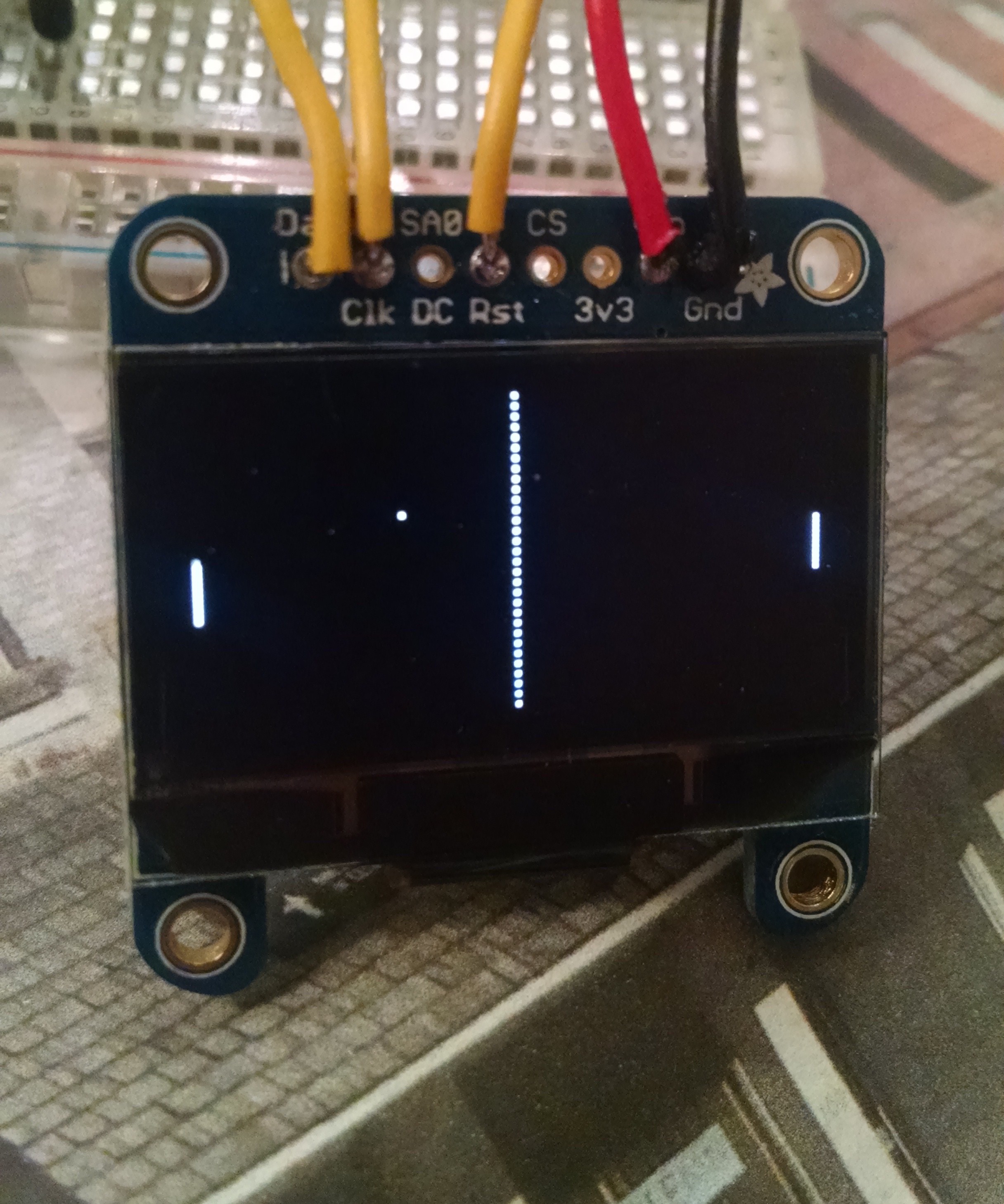
For Pong to work, though, I needed to wire up the three navigational buttons. I used a lesser-known digital mode on the Arduino called INPUT_PULLUP. It pretty much does what it says. It pulls one end of the switch to 5V, and the other one's connected to ground. Though the input is flipped (LOW is closed and HIGH is open), I don't have to connect the switch to 5V, ground and the input pin, which will save space in the final design. I wrote a quick debouncing function, booted up Pong, and lo and behold, I got a little arcade action on my tiny screen. There's one bug that wasn't there in the JS version, though: the ball doesn't bounce off the bottom edge of the floor; it just kills its own sideways velocity. Well, there's always time to fix that. Only feature that's missing is showing the computer's and the player's scores, but that again can wait.
![]()
The next thing I decided to tackle was how someone will switch between "apps" on the watch. At first I tried having different modes for time, and games, and other things that you would cycle through by pressing two directional buttons (one "up" or "right," the other "down" or "left"), and then go back to a main menu by pressing a select/back button. In the code, this got a little complicated and probably would have involved pointers for the different menu variables, so I decided to take out the "main" menu and just have the middle button cycle through each of the modes; in Pong mode, the directional buttons just play the game, not cycle between anything. In the timekeeping mode, pressing either directional button switches between analog and digital timekeeping. The one thing that's a little bothersome is that it takes longer to switch from digital to analog than from analog to digital. Here's a video of everything in action:
I already have the code for a stopwatch, which will probably be a separate mode. If I have time to integrate the small vibration motor I bought, then I'll add a fourth mode for an alarm.
-
Emulator
12/21/2014 at 20:39 • 0 commentsFrom now until Wednesday, I won't be around to work on the physical watch. The same will be true from Saturday through New Years. Such are the holidays. So, to make sure I'm not completely wasting my time, I decided to write an emulator to test on. You can find it at it's current stage on Dropbox, and check out the source in this project's GitHub Repo. Both links are in the sidebar.
It turns out Adafruit's Graphics Library doesn't have any documentation to my knowledge: I have to find out how shapes are drawn by writing the code and testing it out on the display itself. Not wanting to wait four days to get something done, I decided to write a little emulator for the OLED display.
A while back, I wrote an implementation of Snake in JavaScript, splitting up an HTML5 canvas into a grid, and individually setting the pixels on that grid to different colors. To draw the game. Looking at the code for the Adafruit library, it turns out that all of the shapes are drawn onto the screen at the basic level using a function called drawPixel(), which I'd already written for my snake game. With a little bit of improvement on my original code, and JavaScript ports of drawLine() and drawCircle() from the original C++ source, I had a 128x64 pixel white-on-black display being simulated in my browser window. Next thing I knew, I had a smiley face staring back at me:
![]()
I also implemented the Arduino function millis(). Between that and the JavaScript Date object, I should be able to emulate the RTC as well as the display. The next thing to do with this emulator is probably to add the three navigational buttons, and start writing code for an analog clock, and then move onto Pong.
The main limitation of the emulator right now is that I can't print text such that it will look and behave the same as on the OLED display. The real library uses a 1KB buffer that's a bitmap of the display; mine just draws straight on the canvas. Because of this, it would take a little more work than I feel is justified to get the ASCII bitmap working with the emulator. I'll use it to get the components that need to have shapes drawn (such as an analog clock or Pong) implemented, but things like the stopwatch and the main menu will have to wait until I get back to the physical watch to be implemented. But if I really get into it, I might implement the buffer and actually make the emulator do everything the final Trinket Watch will be able to do.
-
Basic OLED Watch Code Completed
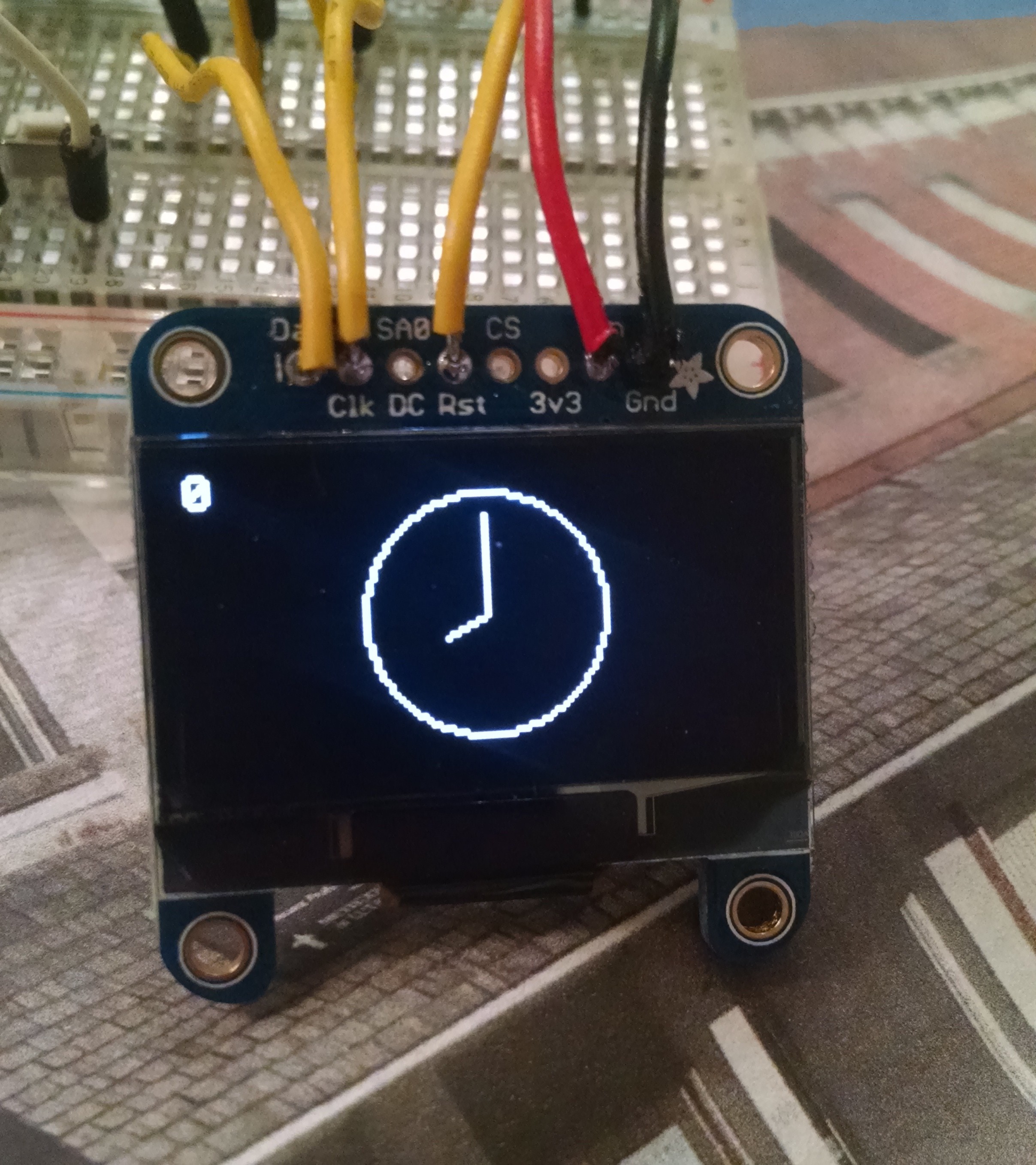
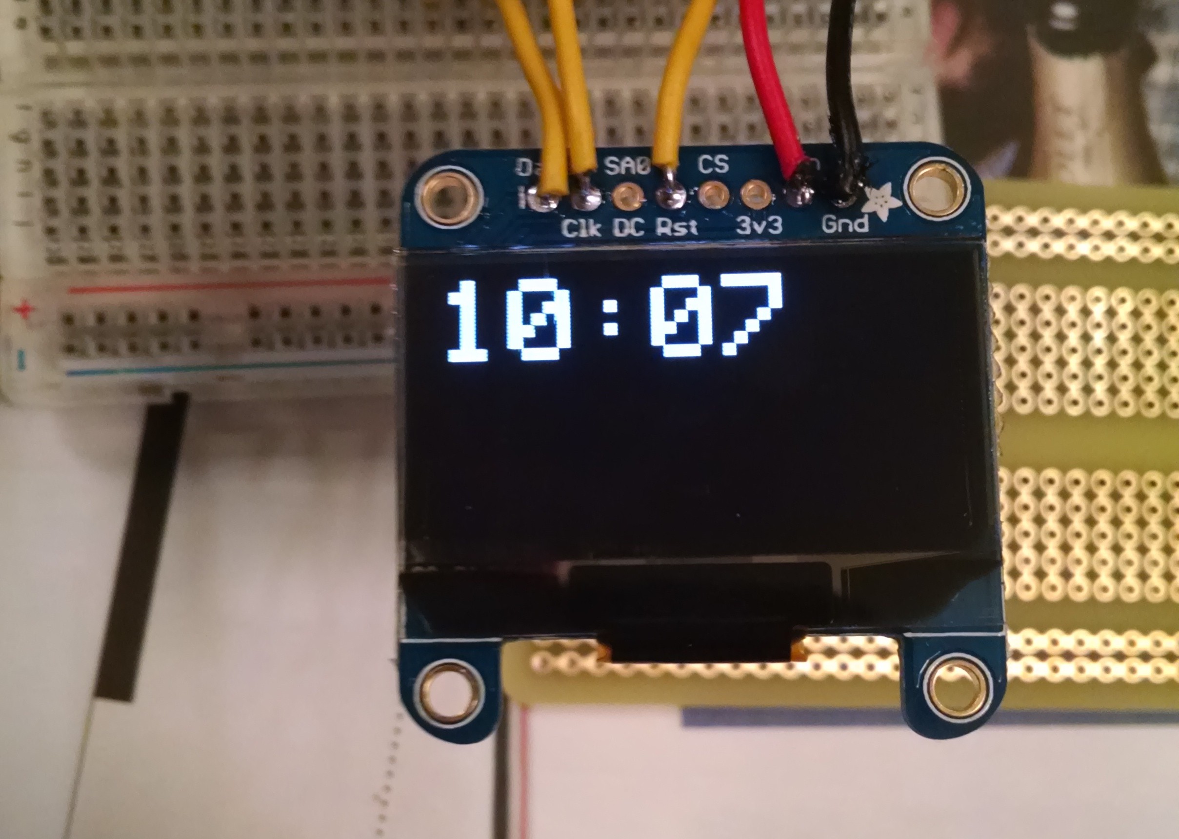
12/19/2014 at 05:15 • 0 commentsAfter I tested the OLED in the last entry, I decided to code up a function that would display a time in a relatively pretty way. I started by just finding the part of the Adafruit example code that renders text on the display, and changed it to print out a string, formatted (HH:MM):
![]()
I then looked at the example code for the RTC module, and it showed that the values from the RTC are put into a Date object, where you can get the hours and minutes from, as well as Unix time. I wrote code that took variables with seconds and minutes and added one minute to the time every 200 milliseconds. Here's the outcome:
(I apologize for the vertical video).
All of my code is now on GitHub, so feel free to check it out! The link will be in the sidebar.
-
OLED Up and Running!
12/19/2014 at 03:03 • 0 comments![]()
OLED works! Next step is to write a small program for the OLED that displays a dummy time, in digital for now, and have it count up minutes, to see if it updates correctly. When that works, I know I can move on to making the RTC kit and wiring that up.
-
Parts Arrived!
12/19/2014 at 01:36 • 4 comments![]()
Parts arrived from Adafruit today! Pictured is all the main components, plus a gyroscope that I accidentally included in the snapshot. After checking the pins on the RTC, it looks like it takes 5V. Well, that won't work well with the 3.3V trinket and 3.7V battery. After some research, it looks like it can work with 3.3V logic by not soldering in the two pullup resistors. Easy enough. And for the voltage input? Let's hope that when Adafruit writes that it "works best" at 5V, it actually works at all at 3.3V. Hopefully I can test the OLED tonight with an Uno, and possibly poke around with setting the RTC.
-
Quick Calculation
12/18/2014 at 17:10 • 0 commentsTabulating up all of the thicknesses of the components for the watch, it seems like if everything is just stacked on top of each other, the thickness of the watch will be 18.75mm. Putting the backpack and trinket side-by-side, it comes out to a slightly more reasonable 16.75mm. The watch I currently wear is around 15 or 16mm, so it shouldn't be as unwieldy as a 2cm thick watch sounds. I'll see different ways I can arrange the parts once they arrive later today.