0%
0%
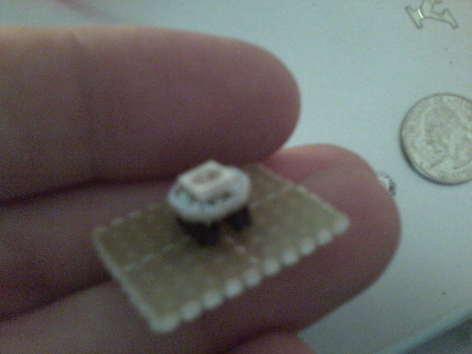
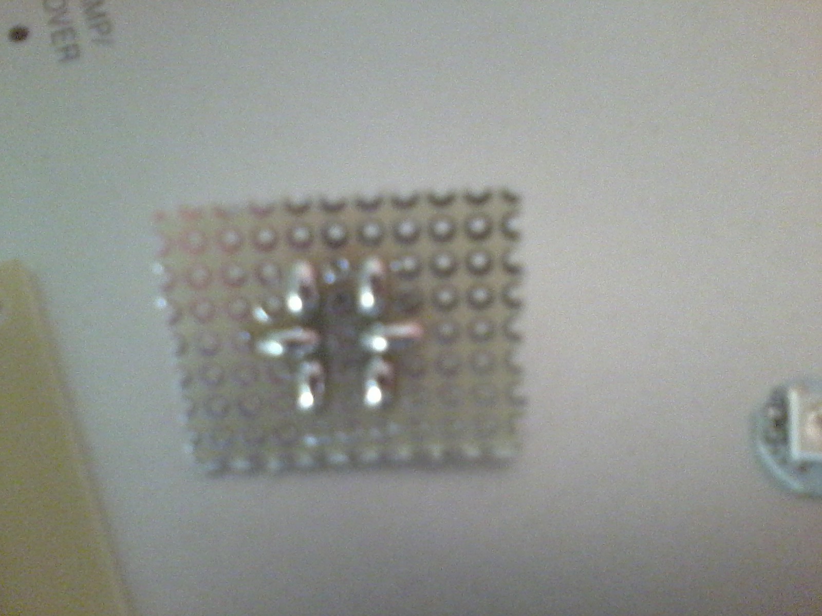
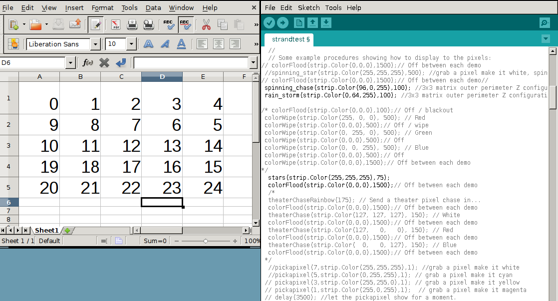
DMX NeoPixel Matrix
There are now two of these lights.
a 5x5 pixel matrix, and a 5x5 projector-type matrix
 Floz
FlozBecome a Hackaday.io member
Already have an account? Log in.
Just one more thing
To make the experience fit your profile, pick a username and tell us what interests you.
Pick an awesome username
hackaday.io/
Your profile's URL: hackaday.io/username. Max 25 alphanumeric characters.
Pick a few interests
Projects that share your interests
People that share your interests
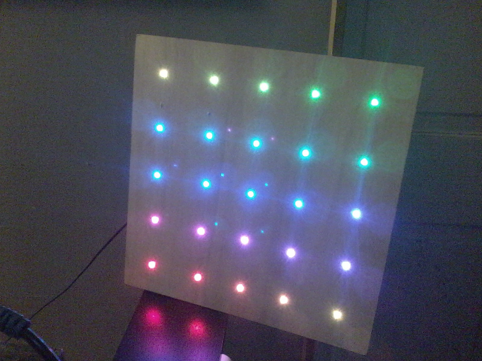 Sorry for the crap quality pictures and video, I have a crap smartphone.
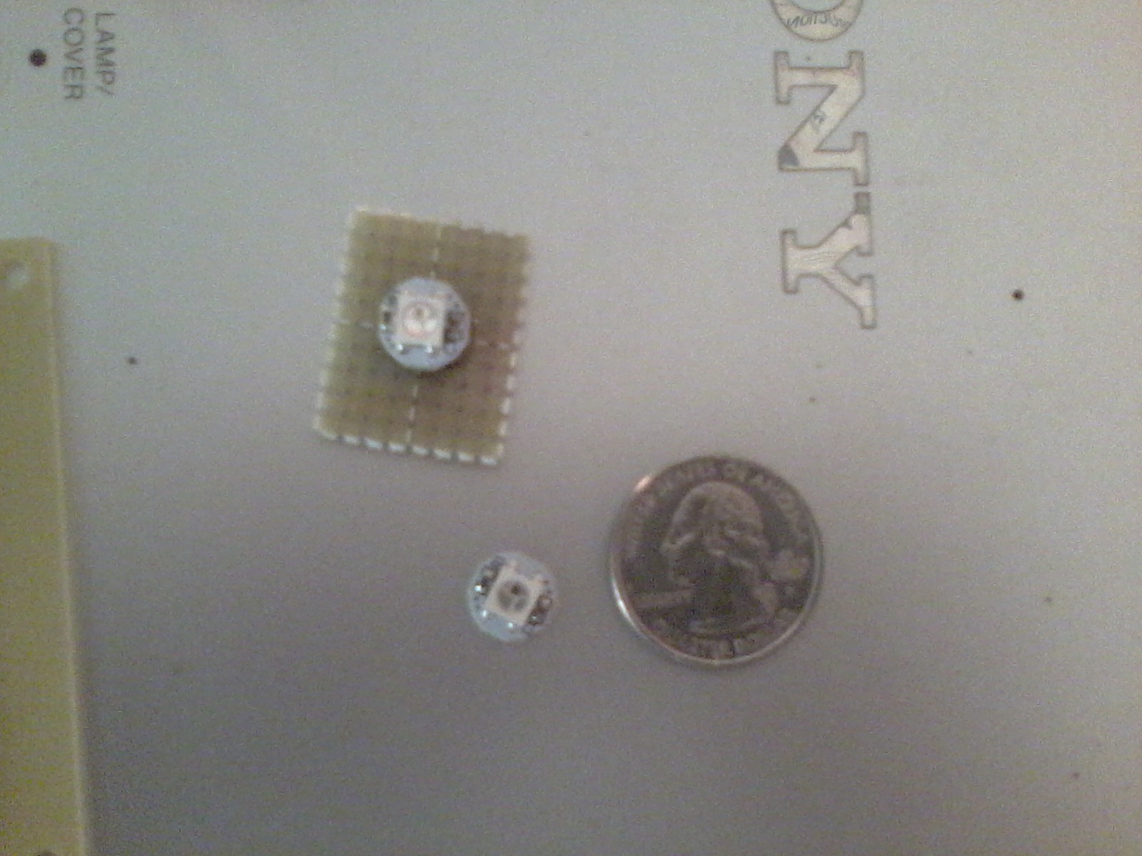

 dBSound Bracelet
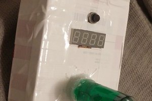
 AndyMac
 davedarko
 Timescale