Close
0%
0%

Beaglebone Black 8" LCD Cape for under $10

Similar projects worth following
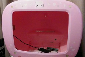
In this project, I try to get my (never opened since I got it for many years ago) Digital Picture Frame to work as a LCD cape for my Beaglebone black.
The motivation for this project is as follow.
1: This is my first time working with embedded linux, and i want to learn my way around.
2: I do need a display for my newly acquired bbb. A a 7" 800x480 cape is about $100
3: It almost free, I already have a 8" SVGA led panel in that DPF.
4. I have not found any project in this topic, maybe I'm the first one to do this. Yohoo!!!

First, here is what i have:
A Element 14 Beaglebone Black Rev C with 4 Gb eMMC runing debian
A 8 inch 4:3 ratio LED backlight LCD panel with 800x600 pixels
Prototype prefboard, wire mm.

What else do i need?
1. FPC cable connector, 50 pins from ebay (ebay link)
2. 50 wires cable and connector, will only need them for prototyping.
3. Div. stuff for soldering the cape.
4. Datasheet for the LCD panel. I found this one on the internet, not exacly the same number as my panel but it seems like they are compatible (AT080TN52 Final- SPEC(V01)). I needed to trace the signals from the original driver board to verify that all the signals are on the same pins of the LCD connector.

Now that i have all i need, the next step is to lean how to make capes for the bbb. There is alots of information about how to load a device tree, how to make the bbb load/unload a specific cape at start etc. and as a newbie, I'm really grateful that there is so many good documentation in this topic. There is no better place to look if you want to make your own LCD cape than Circuitco's 7 inch cape BB-BONE-LCD7-01. The only downside is that this cape is 800x480 and that the pixel clock is runing at 30 MHz while my panel is a 800x600 and 40 MHz.[Edit: seems like that other timing specs like front porch, back porch mm is way off too.]

For the first test, I wired all 16 data signal and 4 control signal to my LCD the same way as the CircuitCo LCD7. Then i used all the LCD bias voltages ( VACC, VGH, VGL, VCOM) from the old driver board and set the scaning direction to Lefl to Right, Up to Down, no Dithering and Data Enable mode.

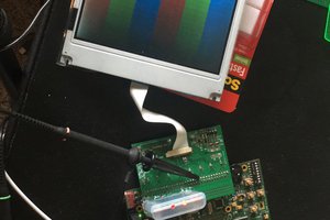
I load the original device tree for CircuitCo BB-BONE-LCD7-01:00A3 as it is just to test and ......Tada.. I have a picture on my LCD ;)

Wow that's good news isnt it. This mean that the hardware is working perfectly. The display driver is for a 800x480 pixels display, so the weird picture that I get is expected, what i didnt expect to works is the pixel clock that is 30 MHz instead of the stated (typical) of 40 MHz for my panel....

Now that I know this can work. The next steps is to modifiy the device tree to fit my panel and recompile it. Don't think there will be any disaster there anyway, but i will keep my fingers cross.

Update 2015-01-08:

Now I have my native resolution on my display :) And all I can say is that it was easy to get the hardware to work but the software/driver bit is quite confusing and time consuming.

I end up using "kms_force_mode=video=LVDS-1:800x600M@60e" in the uEnv.txt file. That M before @ is the key here! and you can find your video adapter from "/sys/class/drm/card-0-LVDS-1"


  • Project status and conclusion

    dennis.d.trinh02/25/2015 at 10:37 0 comments

    As of today, this project has been online for 1.5 month and already has 26 people following and received 8 skulls. That is pretty awesome regards how incomplete this weekend project is. I would like to look at this project as a "Proof of concept" and not a project where I go from design to manufacturing a finished product.

    I managed to make a LCD cape out of a digital photo frame with minimal external hardware and to a very low cost, but not without some shortcoming. Before I put this project aside, I could like to name a few of them and how to (possibly) solve those problems.

    First off is the need of voltages generation for the panel (VGH, VGL, AVCC, VCOM) and backlight. I used the old driver board to drive the panel and saved tons of work and at no expense, but it's certainly not a pretty solution.
    For a neater solution, I can use Ti's TPS6510x. It's a "Triple output LCD supply with linear regulator and VCOM buffer" that has a 1.6 MHz switching frequency and offer many other features like fault detection (except TPS65101) and <1% output voltage accuracy. Ti's TPS61080 is a wildly used for LCD backlight application and is fairly simple to use.

    The next thing is touch functionality and it can be fixed by adding a touch panel. Capacitive touch panel for 8" 4:3 panel is nowhere to be found, but luckily there is many resistive ones out there in the wild (Ebay). Resistive touch use 4 AN input while capacitive use I2C bus plus one interrupt signal and both type is supported in the latest kernel.

    The last thing I want to talk about is noise immunity and the need for a buffer IC. My answer is no, at least not for this panel anyway. I tried to replicate the worst case for a poor LCD panel (50 cm long wiring and wraping around the old driver board (2 boost converter) without a buffer IC). Everything works fine and the picture is as crispy as it can get. Color wise its 16 bit color so that's what you get. For people who feel like they need more than 16 bit, there is nothing to stop them from using up to 24 bit in exchange for some IO pins.

  • SSH to your Beaglebone from android.

    dennis.d.trinh01/12/2015 at 20:46 0 comments

    This is my setup: Android tablets runing kitkat and a Otg cable plus SSH Client app from play store.

    It works fine if you can live with that horrible soft keyboard, and i think this might be useful if you need to make some minor tweaks to your bbb when runing in a remote place and you dont have your laptop with you.

    I managed to edit, compile and load a new device tree overlay with this setup, but damm that keyboard is hard to live with.

View all 2 project logs

Enjoy this project?

Share

Discussions

dorisvaldo.paiva wrote 06/08/2016 at 19:31 point

Hi, I don't know if miss some point, but where is your schematics for this project? can you share it?.

Best Regards D.B.Paiva

  Are you sure? yes | no

dennis.d.trinh wrote 06/14/2016 at 10:02 point

Hi Dorisvaldo, no there is no schematics included, and the reason is because it depends on LCD panel that you have. There is a good example  how to wire a LCD to your BBB that I already mentioned in earlier post from Kumar. 

  Are you sure? yes | no

Tachyon wrote 02/20/2015 at 20:25 point

I'm interested in seeing more info on this project. IE full schematics, code, etc.

As for your Android soft keyboard SSH complaints, these are easily resolved with the Esc Hacker's Keyboard which is an essential part of any Android user's toolbox.

https://play.google.com/store/apps/details?id=org.pocketworkstation.pckeyboard&hl=en

  Are you sure? yes | no

dennis.d.trinh wrote 02/21/2015 at 07:04 point

Hi Tachyon!

Thanks for the tip, Esc kb is quite handy. Do you plan to make a lcd cape? Witch panel are you going to use?

  Are you sure? yes | no

Tachyon wrote 02/22/2015 at 01:56 point

I'm not sure yet. I have to dig up the several I have kicking around and see if any can be similarly hacked. 

That's why I'm interested in more details on this so that I can understand it and then possibly modify the process for other hardware.

Thx.

  Are you sure? yes | no

dennis.d.trinh wrote 02/22/2015 at 21:11 point

what ever panel you are going to use, make sure you have the datasheet for that panel. From there you can take a look at the schematic for other lcd cape to learn how they wired there panel. I dont have any schematic for my project because i used the datasheet for my panel and pinout table for the bbb.

Take a look at how those cape are designed, and i'm sure you will be able to make one your self.

http://www.4dsystems.com.au/productpages/4DCAPE-43/downloads/4DCAPE-43%28T%29_datasheet_R_1_9.pdf

http://elinux.org/CircuitCo:BeagleBone_LCD7

  Are you sure? yes | no

Kumar, Abhishek wrote 02/22/2015 at 21:43 point

+1. 40 pin panels have voltage generation circuitry already built into the LCD, 50 pin ones need extra work.

BTW, I'm uploading details of my work shortly.

  Are you sure? yes | no

dennis.d.trinh wrote 02/23/2015 at 08:20 point

btw, 60 pin ones like CircuitCo's need extern gamma circuitry too. Not the one you want to use. 

Do you plan to do a commercial grade Cape? I saw your (Kumar A) Google SOC project, really nicely done!

  Are you sure? yes | no

Kumar, Abhishek wrote 02/12/2015 at 09:56 point

I am working on a hardware design for a cape independently with a 7" LCD which happens to have a 50-pin connector as well and just happened to stumble upon this.

I'll let you know as and when the design is ready so you could try it out.

  Are you sure? yes | no

dennis.d.trinh wrote 02/13/2015 at 10:11 point

Hi Kumar, nice to see someone else doing the same thing. When I started my project, i tried to find a similar project but cound not find any and that's why i post mine here. Feel free to ask any question if you have any. I will do my best to answer those I can to you.

/Dennis

  Are you sure? yes | no

Similar Projects

Does this project spark your interest?

Become a member to follow this project and never miss any updates