Orlando Hoilett
-
Placing pedometer on wrist and transmitting data via bluetooth
01/20/2015 at 01:30 • 1 commentFrom Sunday, January 19, 2015
After doing some work on the continuous heart rate monitor and hitting a dead end, I started working on placing a pedometer on my wrist. I had previously written some code for an Arduino pedometer, so I moved my Arduino pedometer from my waist to my wrist. It appeared to work out well. I was a little nervous about decoupling the movement of my arm from the movement of my body. While I am actually walking, this should not be a problem. But, while not walking, but simply moving my arm, the current code will not work.
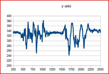
There are 5 "zones" in this data. The first is me being still, then walking forward 4 steps without swinging my arms, then me being still, then walking forward 4 steps while swinging my arms, then me being still.
My accelerometer data is not as clean as I thought it would be and I am not entirely sure why. I may need a new module or something.
![]()
/* FILENAME: pedometer_V_0_1_0.ino AUTHOR: Orlando S. Hoilett EMAIL: orlandohoilett@gmail.com WEBSITE: http://www.instructables.com/member/ohoilett/ http://hackaday.io/orlandohoilett https://www.youtube.com/user/shoilett1 VERSION: 0.1.0 AFFILIATIONS: Calvary Engineering Family Group, USA - a group of DIY enthusiasts UPDATES: Version 0.0.0 06/21/2014:1654> Uses a simplified algorithm to detect steps. Right now, we are using thresholding to determine a step. Right now, that's an AC signal of 40 raw ADC. The sampling period for a step is 600 ms. Used an op amp (MCP6002) in non-inverting configuration with a gain of 1.5. Version 0.1.0 08/16/2014:1736> Changed thresholding to 70 raw ADC and sampling period of 800 ms. A non-inverting op amp (MCP6002) with a gain of 2 was used. Also added Bluetooth functionality to help in ES140 demo. DESCRIPTION This program is the backbone of a pedometer. It detects steps by changes in acceleration as a person is walking. Citations: 1. Jef Neefs (neefs@gmail.com) and Jeroen Doggen (jeroendogeen@gmail.com) for their AcceleroMMA7361 library. 2. HobbyComponents.com for Bluetooth code snippets FILE: ARD_BLUETOOTH_SERIAL_MODULE_HCARDU0004_Example.pde DATE: 17/07/12 VERSION: 0.2 DISCLAIMER This code is in the public domain. Please feel free to modify, use, etc however you see fit. But, please give reference to original authors as a courtesy to Open Source developers. */ //library include #include <AcceleroMMA7361.h> //initializes pedometer object AcceleroMMA7361 myPedometer; int x; int y; int z; int maxVal = 0; int minVal = 1023; int array[10]; int index = 0; unsigned long tCalib = 0; unsigned long tOld = 0; unsigned long tNew = 0; int steps = 0; const int CALIB_TIME = 5000; const int threshold = 50; //change in Z acceleration const int samplingFreq = 600; //milliseconds //Code for Blueooth functionality #include <SoftwareSerial.h> //DIO used to communicate with the Bluetooth module's TXD pin #define BT_SERIAL_TX_DIO 10 //DIO used to communicate with the Bluetooth module's RXD pin #define BT_SERIAL_RX_DIO 11 //Initialise the software serial port SoftwareSerial BluetoothSerial(BT_SERIAL_TX_DIO, BT_SERIAL_RX_DIO); void setup() { Serial.begin(9600); BluetoothSerial.begin(57600); //sleepPin, selfTestPin, zeroGPin, gSelectPin, xPin, yPin, zPin //functions depending on which version I am using myPedometer.begin(3, 12, 5, 4, A0, A1, A2); //myPedometer.begin(10, 12, 10, 9, A0, A1, A3); myPedometer.setARefVoltage(5); //sets the AREF voltage to 3.3V myPedometer.setSensitivity(HIGH); //sets the sensitivity to +/-6G myPedometer.calibrate(); // Serial.println("Calibrating pedometer."); // while (tCalib < CALIB_TIME) { // } } void loop() { tNew = millis(); x = myPedometer.getXRaw(); y = myPedometer.getYRaw(); z = myPedometer.getZRaw(); if (z > maxVal) { maxVal = z; } if (z < minVal) { minVal = z; } if ((tNew - tOld) >= samplingFreq) { if ((maxVal - minVal) >= threshold) { steps++; } tOld = tNew; minVal = 1023; maxVal = 0; } // Serial.print(x); // Serial.print(","); // Serial.print(y); // Serial.print(","); // Serial.print(z); // Serial.print(","); // Serial.print(steps); // Serial.print(","); // Serial.println(tNew); BluetoothSerial.print(x); BluetoothSerial.print(","); BluetoothSerial.print(y); BluetoothSerial.print(","); BluetoothSerial.print(z); BluetoothSerial.print(","); BluetoothSerial.print(steps); BluetoothSerial.print(","); BluetoothSerial.println(tNew); if (Serial.read() == '0') { Serial.end(); } } -
Initial tests for continuous heart rate monitoring
01/20/2015 at 01:09 • 0 commentsCombined a basic current to voltage converter circuit for the photoplethysmograph and my MMA7361 acceleromteter and took some data of my plethysmogram and the movements of my arm. I got some data, but do not know how to process them as yet.
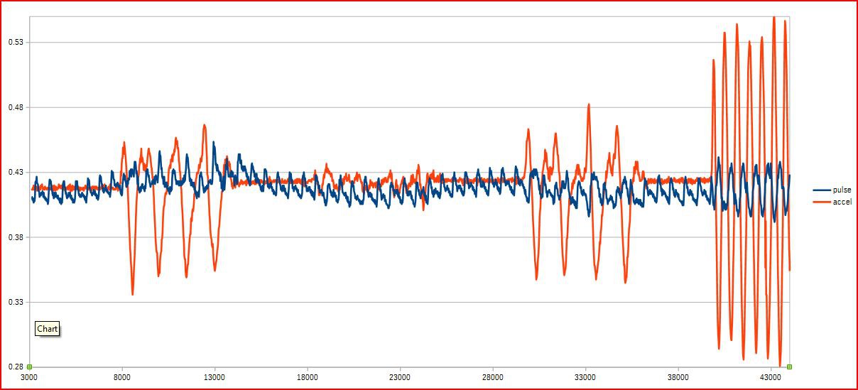
The orange signal is acceleration data (in the z-direction) and the blue signal is the pulse signal. There are a few distinct "zones." The first is me being still, then moving my hand up and down, then being still, then moving my arm left and right, then being still, then moving my hand up and down, then being still, then moving my hand up and down more quickly. The x-axis is time in milliseconds and the y-axis is signal amplitude.
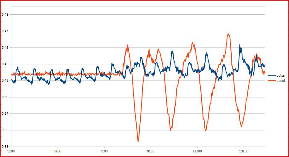
The second picture is zoomed onto one section.
![]()
![]()