 Nick Sayer
-
1Step 1
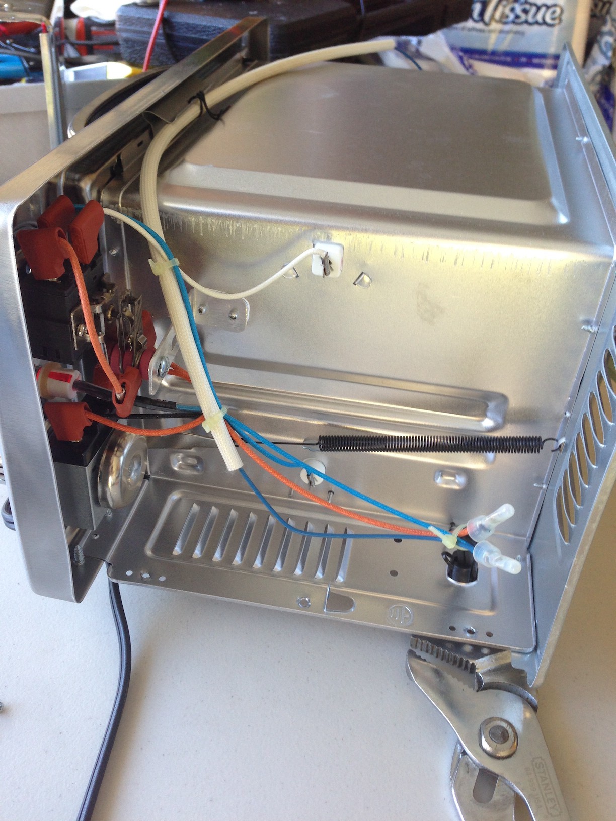
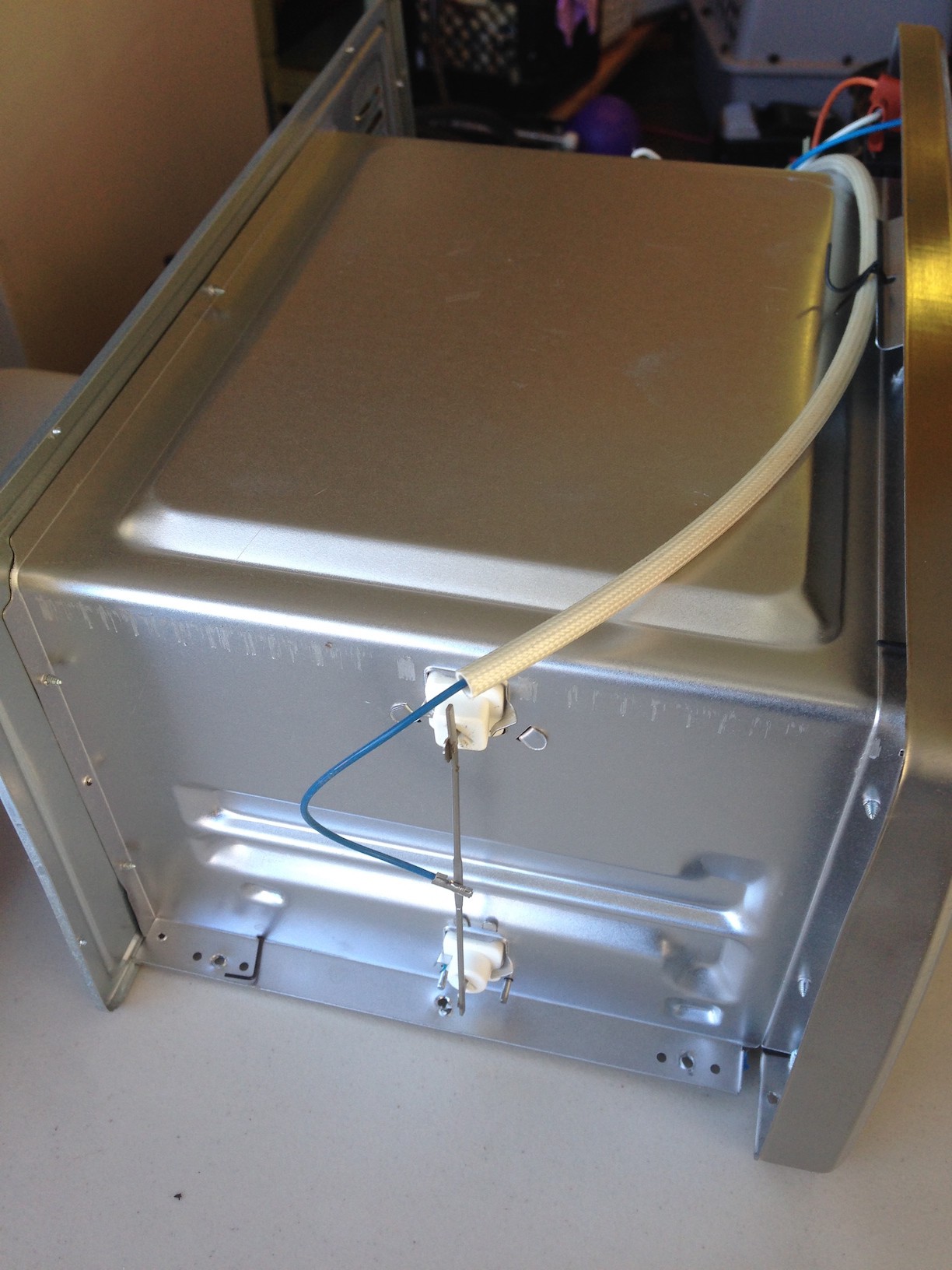
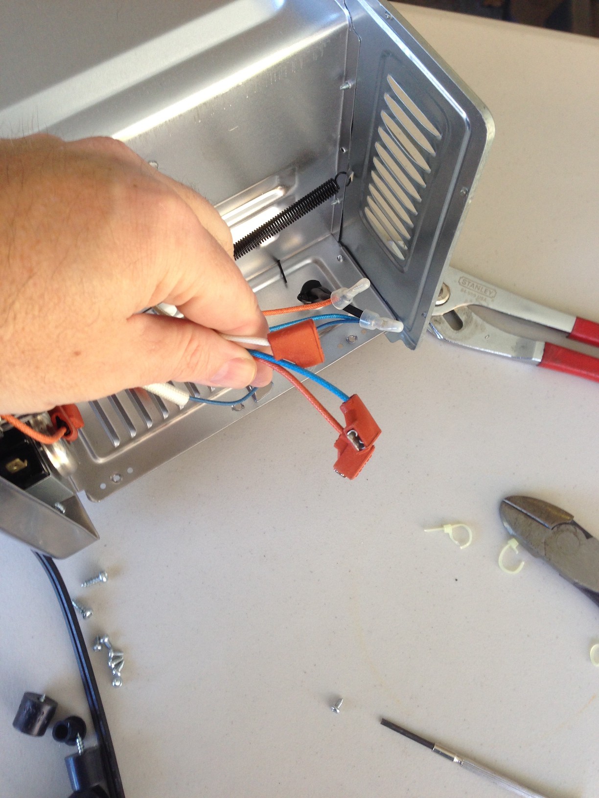
First, take the oven apart enough to get to the internal wiring. What you want to wind up with is that the neutral line of the AC cord connects to one side of the elements. The hot line of the AC cord comes to a 1/4" QD female terminal, and the non-neutral-connected side of the two elements (or sets of elements) comes out to two other 1/4" QD female terminals.
![]()
![]()
![]()
-
2Step 2
Assemble the power board, then connect the incoming hot line from the AC cord to the HOT terminal, and then each of the two element lines to the OUT1 and OUT2 terminals. It doesn't matter which element connects to which terminal.
-
3Step 3
Drill four 1/8" holes in the outer sheet metal enclosure for mounting the power board. Select the mounting location carefully so that the heat sinks are as far away from the heat of the oven as possible, but still as well ventilated as possible, but also insure that you can't poke anything through any ventilation slots/holes that might touch the power board.
Mount the power board using #4 bolts, nuts and 1/4" standoffs.
Drill a hole sized for the cable grommet. Attach the three wires in the cable to the input terminal block on the power board. Route the cable out the hole and install the grommet.
-
4Step 4
Re-assemble the oven. Plug it in to AC power carefully the first time. Any sign of activity at this point is likely a problem.
To test the power board, apply a current-limited 25 mA of at least 2 volts (for 5 volts, use a 150 ohm series resistor) across each input in turn. With the current applied, the appropriate heating element should turn on. With the current removed, it should turn off.
-
5Step 5
Connect the control cable to the OVEN terminal of the controller, carefully noting which of the three wires is the common cathode. For the other two, it doesn't matter which is which.
Connect the K thermocouple to the thermocouple connector on the controller. Take careful note of the polarity. The standard color code for K thermocouples is yellow for positive, and (perversely enough), red for negative. Get this backwards and your controller will register a very odd, probably low, temperature. Route the business end of the thermocouple into the oven. I went through the cleaning door in the bottom and then up to the rack of my oven, but you can also go through the main door, as long as the door can still close without unduly pinching the thermocouple wire. Use uninsulated 22 gauge wire (or equivalent) to tie the thermocouple cable to the rack and route it to a convenient spot. When in use, you want the end of the thermocouple to be as close to, but above, the boards as possible without touching anything.
-
6Step 6
Apply power to the controller. It should show the "Waiting" state and the ambient temperature in the oven. If it reads an impossibly high temperature (model I controllers), then your thermocouple is open. If your controller registers a thermocouple fault (model II), then check the thermocouple wiring or try another thermocouple.
Discussions
Become a Hackaday.io Member
Create an account to leave a comment. Already have an account? Log In.
I am very happy with my version of the Toast-R-Reflow oven. I think having your kit and using the same oven made things easier. Do you know if trimming the length of the themocoupling lead would cause any problems? Also any ideas on an enclosure or a mounting for the controller/LCD rather than just having it lay on the workbench beside the oven?
Are you sure? yes | no
Trimming the thermocouple leads should be ok, but extending them is difficult, as you can't solder to those wires. Even if you could, it would effectively move the "cold" junction away from the thermocouple amplifier, which will lessen the accuracy (unless the extension wires and junctions are made of the same metals as the leads).
I just leave my controller sitting on the bench, but as you note, it's somewhat less convenient. The good news is that the 80x36mm LCD is a very, very standard footprint, so there should be tons of 3D printed case designs that you could adapt.
Are you sure? yes | no