With the board complete, we now move on to testing and programming. Couple things to check with an multimeter before applying any power. Check that there's no short between the supply voltage and ground. Then I check that there is continuity between my header pins and pins on the MCU. This is good for checking if there are any shorts caused by solder bridges.
To program the ATMega328P I use a handy AVR Pocket Programmer from Sparkfun. Since it's based on a USBTiny programmer, the Arduino IDE can burn the bootloader onto the chip.
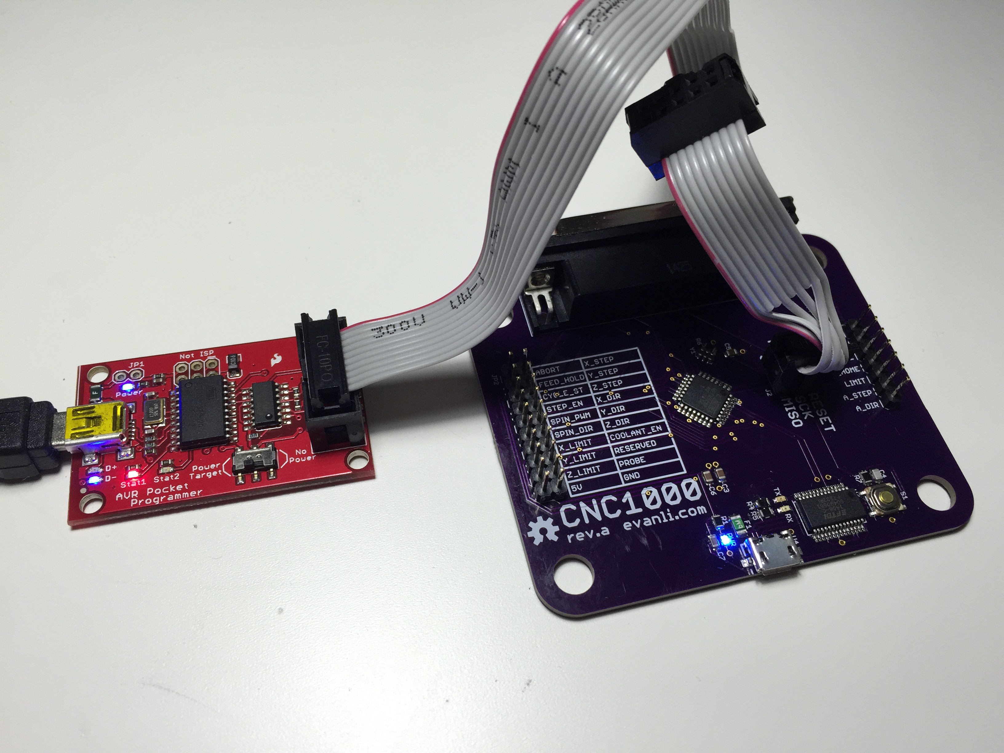
The LED lights up, which is a good sign. Once the bootloader has been burned on by the Arduino IDE, we can use USB via the FTDI chip.
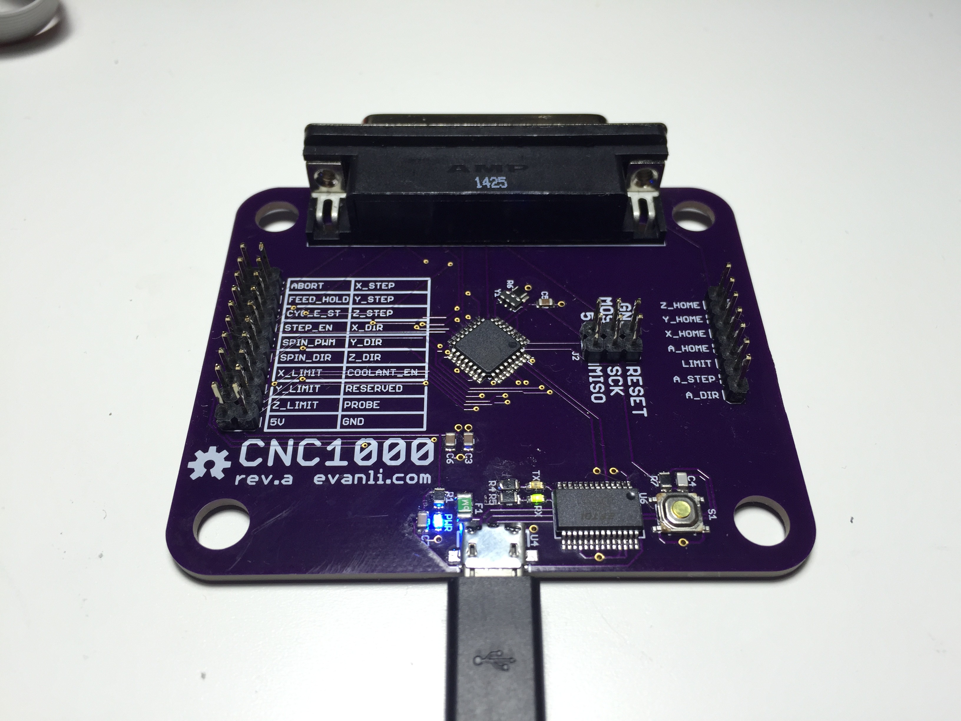
Power LED, RX and TX LED are all working. My computer picked it up as COM16.
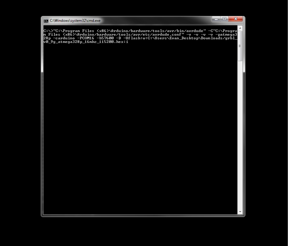
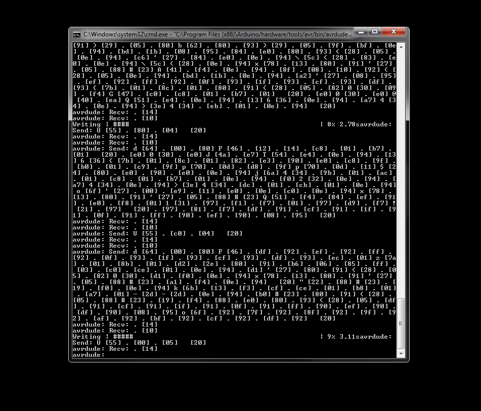
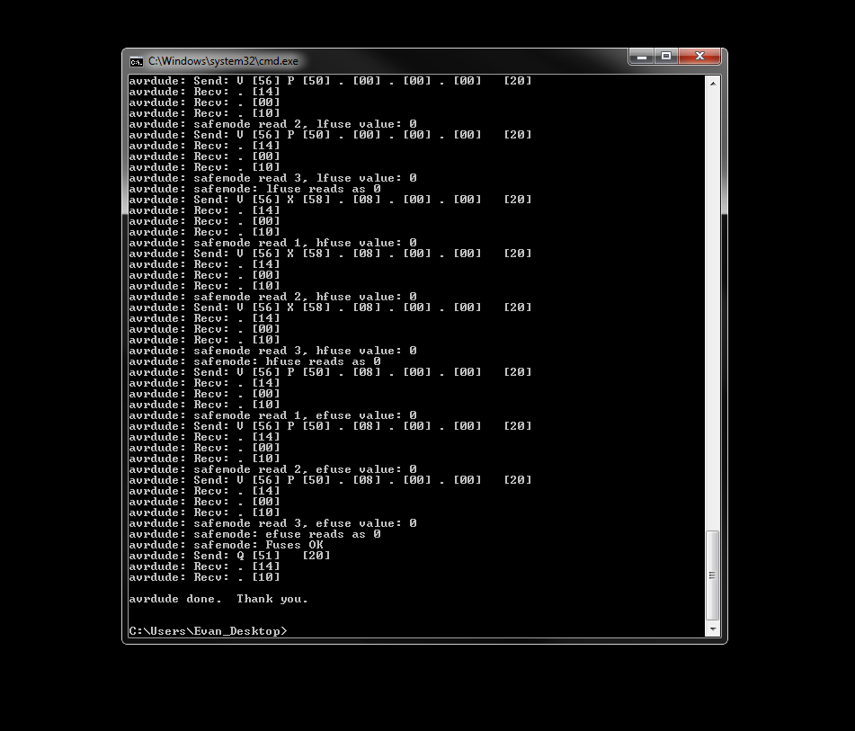
You can grab the latest compiled hex file for GRBL from GRBL on Github. Once you have that, you can load the hex wit AVRDude, which is included with the Arduino IDE.
 Evan Li
Discussions
Become a Hackaday.io Member
Create an account to leave a comment. Already have an account? Log In.