The Big One
-
One More Try for Negative Channel...
06/04/2015 at 15:38 • 0 commentsThe original negative channel didn't end up working properly after all... I must have had some bare wires somewhere that weren't quite touching, because as I was probing it with my multimeter while trying to get the overcurrent light working properly, something sparked and blew a trace (it was pretty cool actually, I had never personally seen a trace blow before! ;-)). Yesterday evening I soldered up another one (I have it down to about 45 minutes now!), but there was a short between VB and GND that I couldn't find, which took me another 2 - 3 hours to track down. (End result: I had put the solder paste on one of the op amps a bit too close to the chip, and there was a bridge between two pins that I couldn't see without taking the chip off the board.)
Anyway, after a long and frustrating time to troubleshoot, I got it working in the end (95% sure this time). The voltage light works, the overcurrent light works, voltage + current limits can be set via the GUI (I had fixed that particular software bug a day or two ago, I don't think I remembered to post about it). More testing is definitely needed, but I think that things are looking good!
Outstanding issues:
- Build enclosure (and make some tools + jigs required to make the enclosure)
- More software work (the burning need at this point looks to be multi-point calibration for current... the voltage setpoint and readout is pretty much linear across the entire range, as is the current readout, but the current setpoint seems to not be defined by a linear function. I need to see how best to do this... @Baruch Even had mentioned the Least Squared Estimate in a comment a few months back relating to this; I had looked into it briefly but had not done enough research to fully understand the method. If anyone has thoughts or comments on alternative approaches, that would be great!
Cheers
-
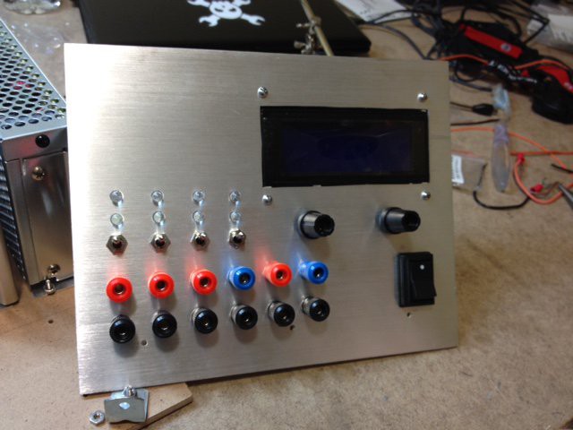
Hardware Completed
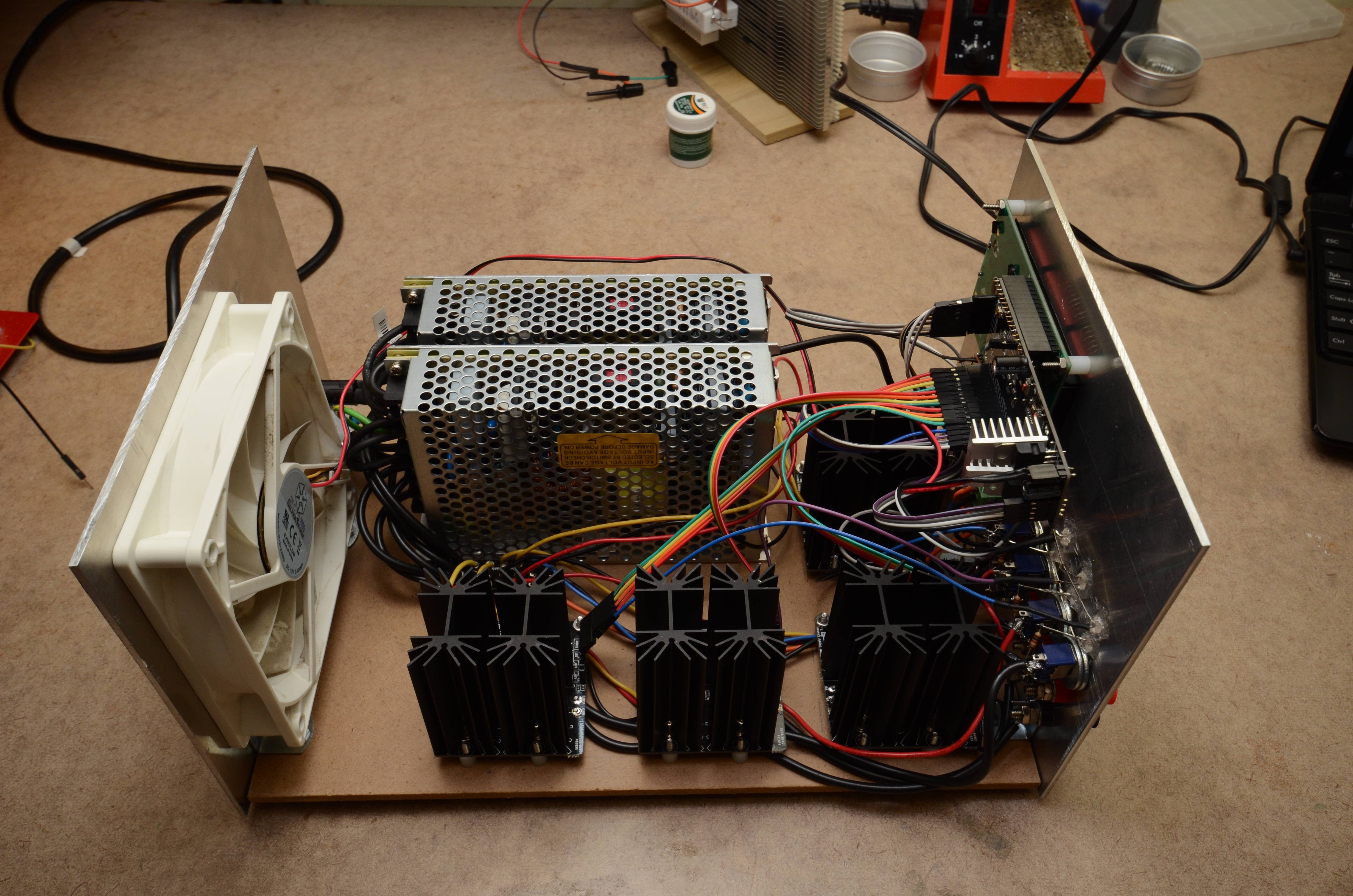
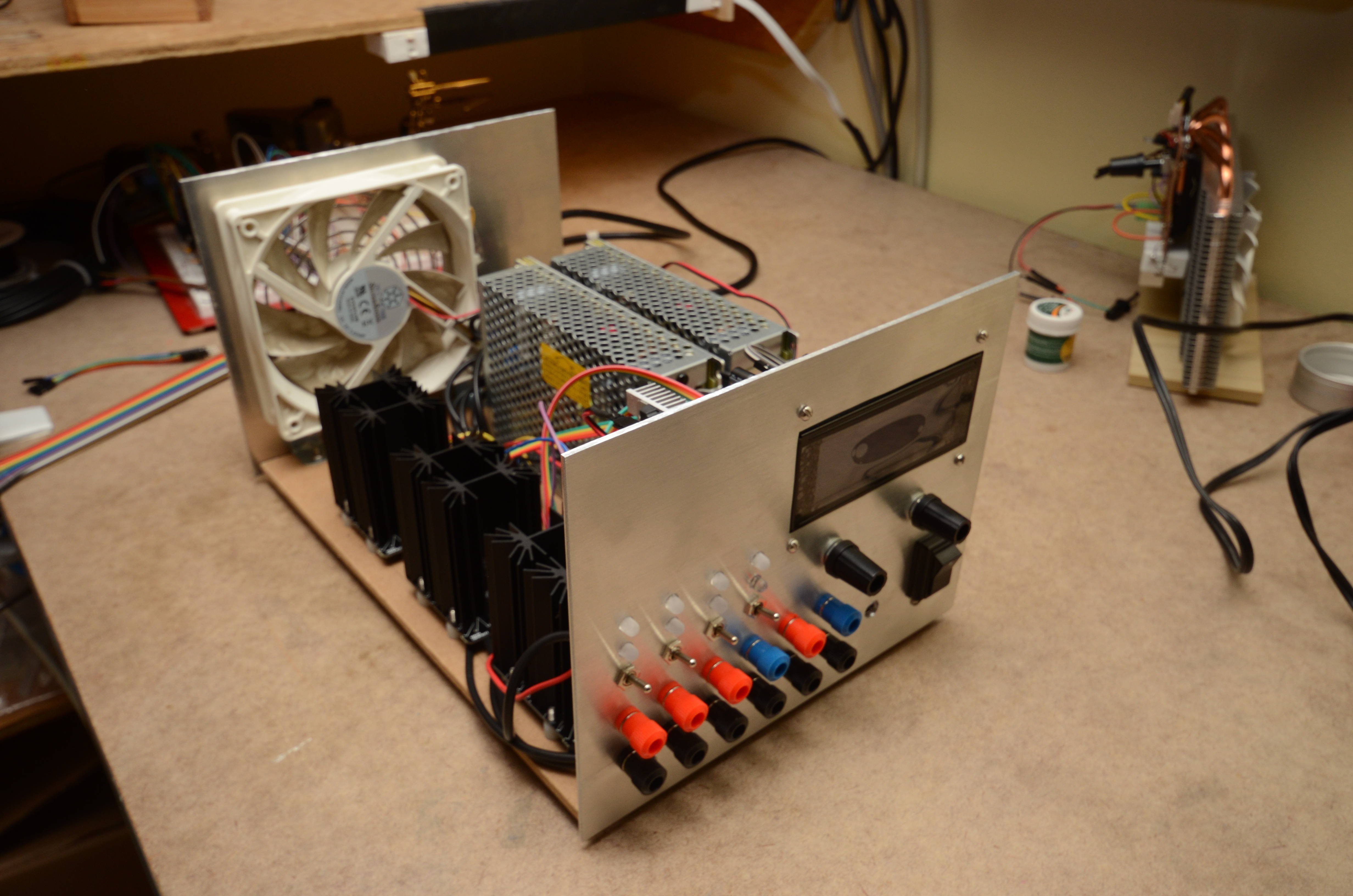
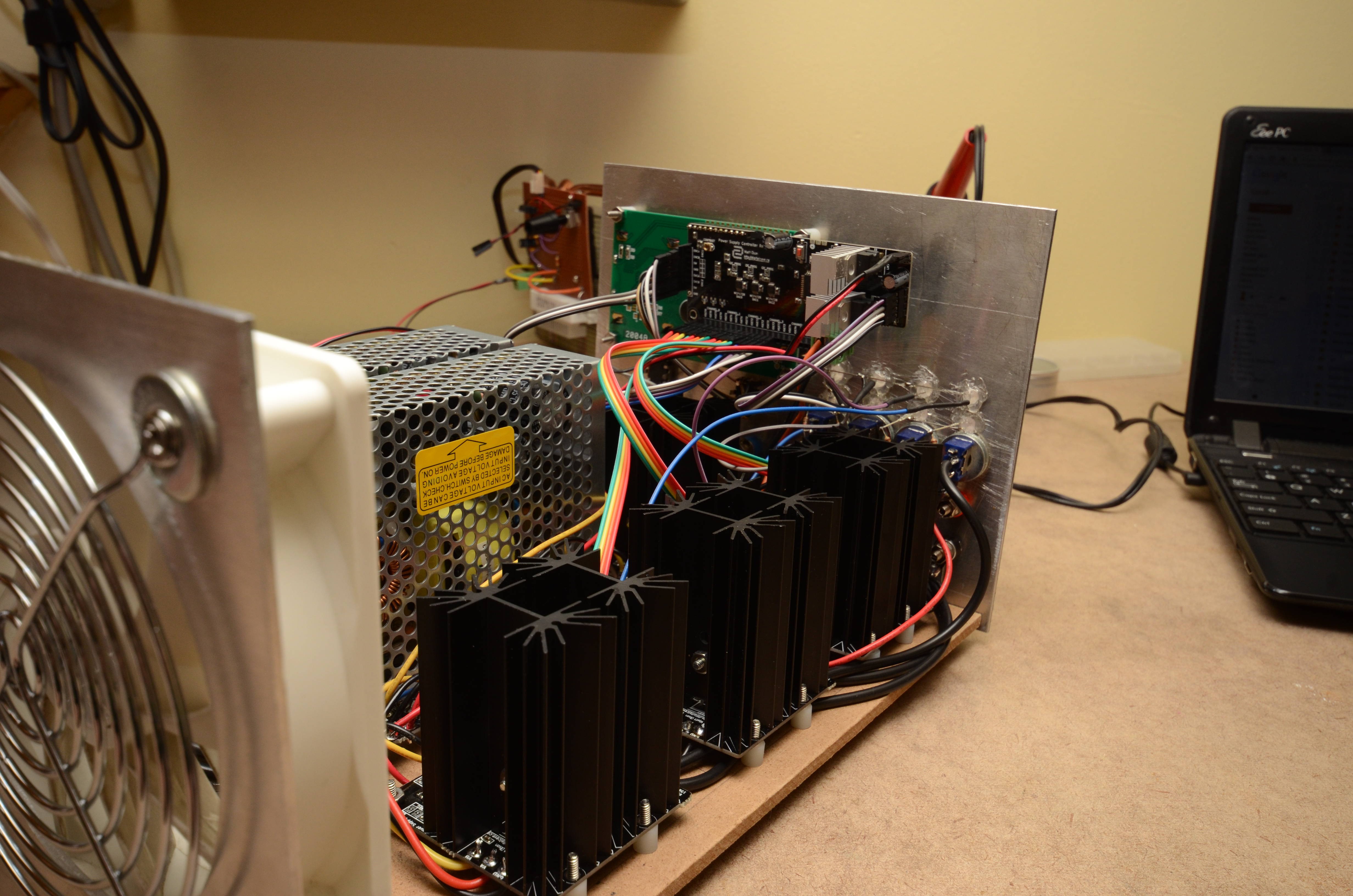
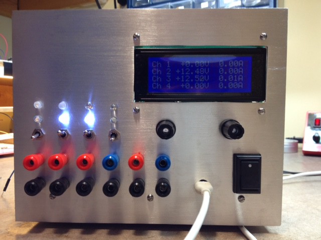
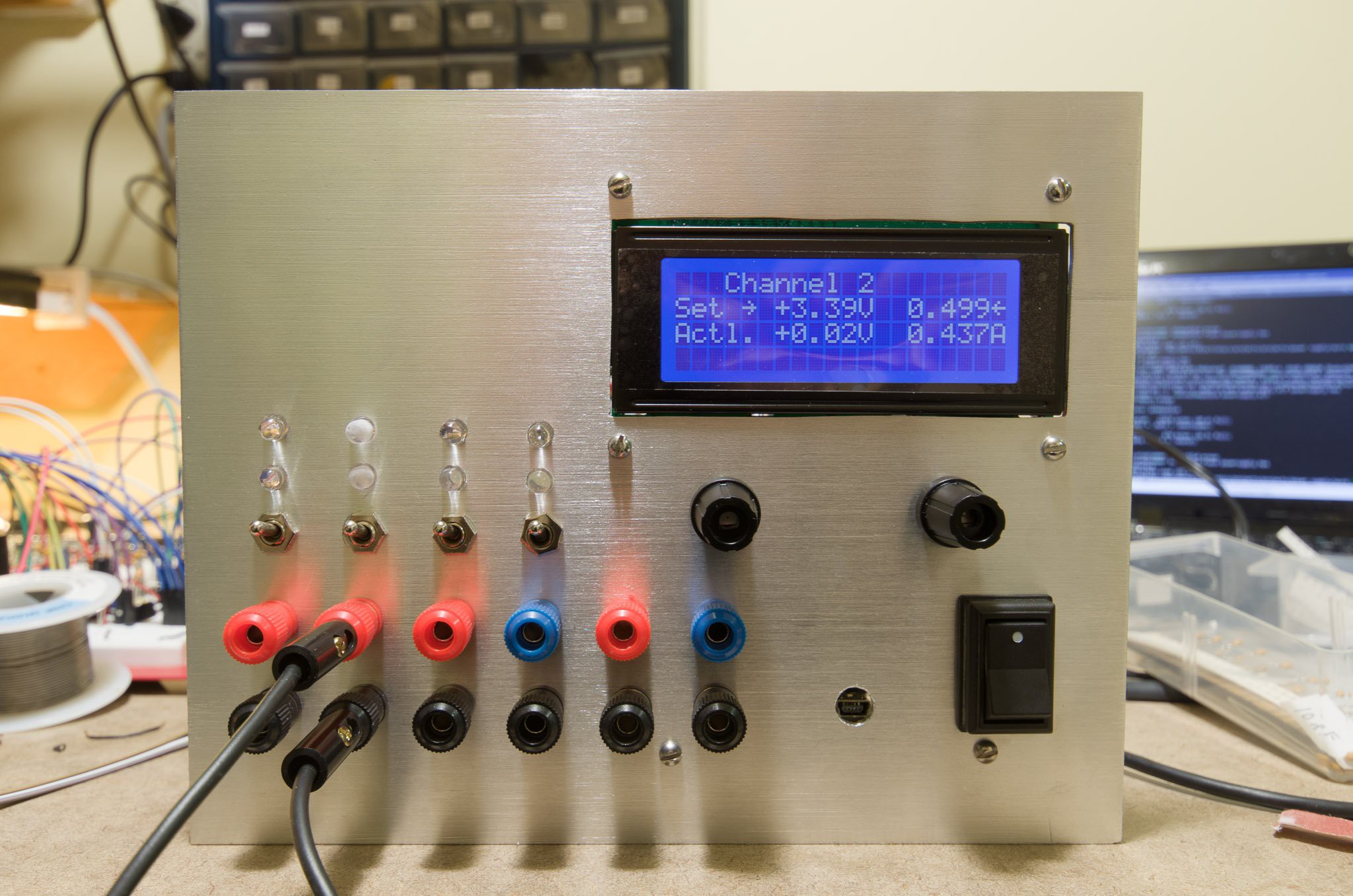
06/02/2015 at 04:18 • 0 commentsThe hardware is now completed and appears to be working properly. I still need to finish writing the software and make the wooden case for the whole thing.
Pictures of the assembled power supply are below. Enjoy!
![]()
![]()
![]()
-
Update - Single Source Power Supply Not Supported
06/02/2015 at 02:48 • 1 commentOriginally I had said that a goal was to be able to use a 12v wall wart with a single controller board to get a 1.7-10v variable output. Today I confirmed that this use case is not possible. You require a dual supply for the regulator board to work (although the negative side requires very little current, so you may be able to get by with a charge pump or something to supply the current). I apologize for the inconvenience; however you can get a couple of cheap switch mode supply for not a lot of money these days so there is really no reason not to go this route. (For instance, I purchased 2x 15v 7A supplies from Mouser for less than $25 CAD each. You can buy similar supplies on eBay for under $10, if you are willing to risk the fire hazard. I have heard that you can link two wall warts to get a balanced supply, but am not sure if this is safe or not, so don't try it without doing your own research.)
-
Third Channel Working
06/01/2015 at 15:42 • 0 commentsYesterday evening I finished the third channel, this time a negative channel. So now I have channels 1, 2, and 4 completed (1 and 2 are 5A positive channels, 4 is a 1.5A negative channel). I had channel 3 soldered up previously, but there was a problem with it so I will need to try again.
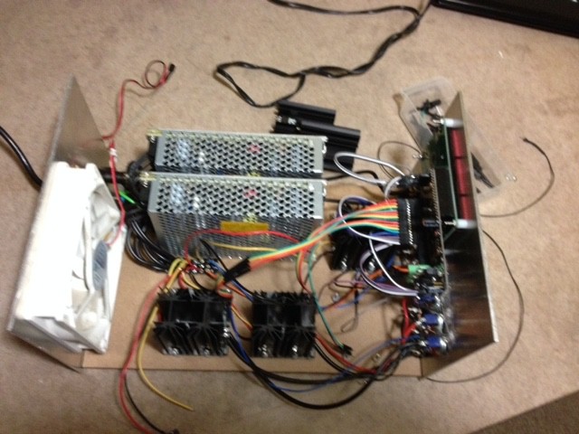
The negative channel is working well from a hardware point of view, but the software needs some work. This is the first time that I had hooked a negative channel up to my controller, and the software does not account for negative vs. positive.
A (very bad) picture is attached below.
![]()
Next steps (in no particular order):
- Solder up the last channel
- A whole bunch of programming
- Wooden enclosure (including making some jigs for the wood working, so this may take a while)
-
Current Limit LED now working
05/30/2015 at 17:37 • 0 commentsEarlier I had mentioned that the current limit LED indicator was not working properly. It would work when current limiting was enabled for very low values (less than 100mA or so), but it would not turn on for higher values.
Today I ran through the entire current limiting control circuit, and figured out what was happening.
The issue occurs because the current limit control output from the op amp does not go higher than about -0.1V for the majority of current limit setpoints. (Given that I am using a PNP transistor for current limiting, that makes sense). The op amp that I was using to turn on the LED was comparing this value to GND; obviously, if the current limit output does not go higher than GND, it will never turn the light on.
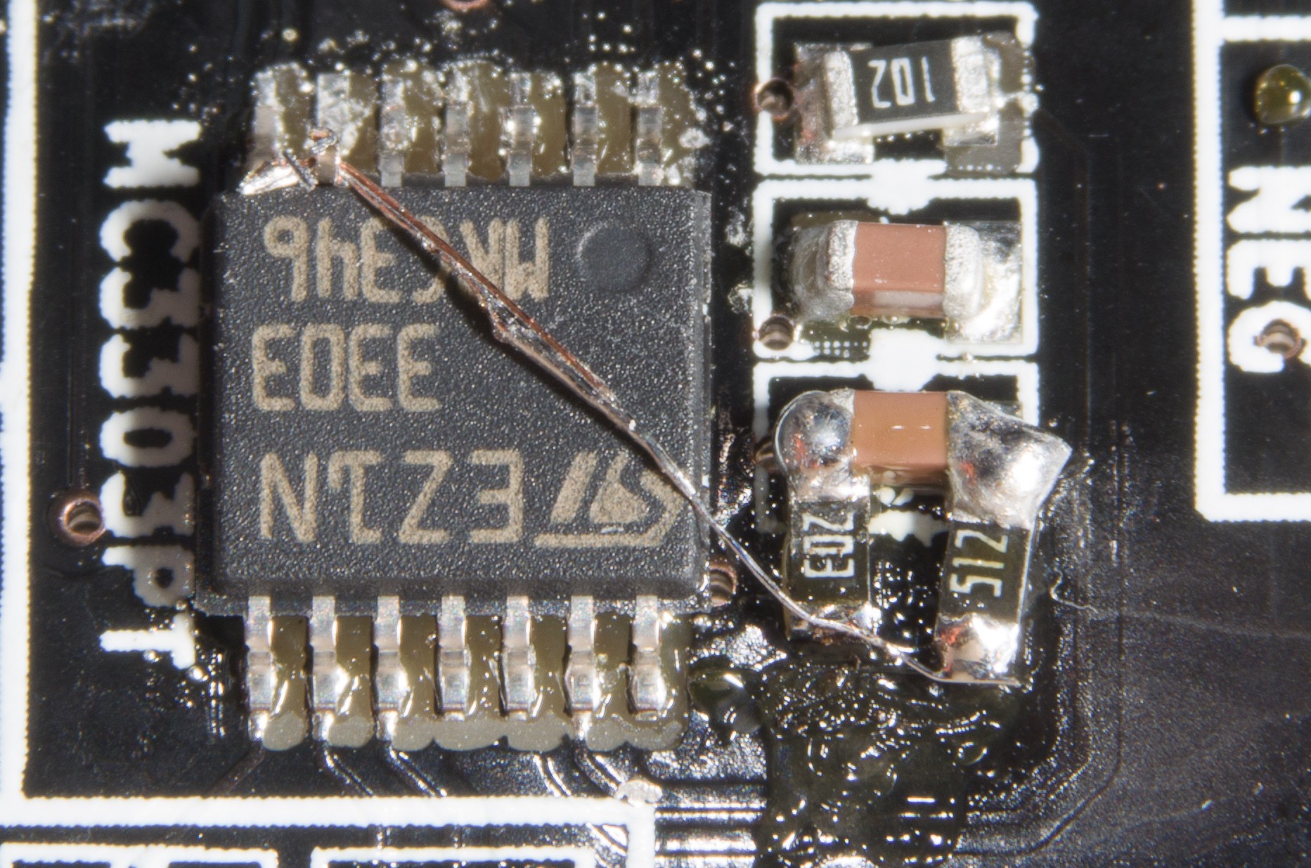
To fix it, I soldered up a voltage divider to get about -3V, and used that as a comparison value rather than GND. Very simple, except that it was reworking an SMD board. I had to lift an op amp pin and solder a jumper between it and the voltage divider output. Luckily there is a decoupling capacitor very close to the op amp which provides me access to -15V and GND in a tidy 0603 package.
WARNING: The photo of the result is below, and looks hideously ugly. Do not view this photo if you have a heart condition, are pregnant, easily scared, suffer from (or enjoy having) OCD, or think that a 1/8W axial resistor is small.
![]()
For scale, the resistors / caps are 0603 and the IC is TSSOP-14.
Unfortunately, I didn't find this until the third board, two of which are already in the enclosure. I guess I need to take them out to do this fix... that will be annoying. :-(
For those following along at home, Rev 1.1 boards will include the proper voltage dividers on the board itself (I just need to figure out if anything needs to change for the negative boards... that will be my next mini project).
-
Another Channel Soldered + Working
05/30/2015 at 01:08 • 0 commentsAnother channel is soldered up and working:
![]()
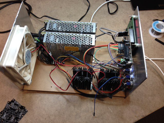
Things are starting to get pretty tight inside the enclosure (at least in places):
![]()
It looks like I will need to improve the software calibration logic. Multiple sample points (especially for current) will probably help accuracy. (The voltage seems to be pretty linear across the entire range, but current is not, and can differ quite a bit from actual readings).
-
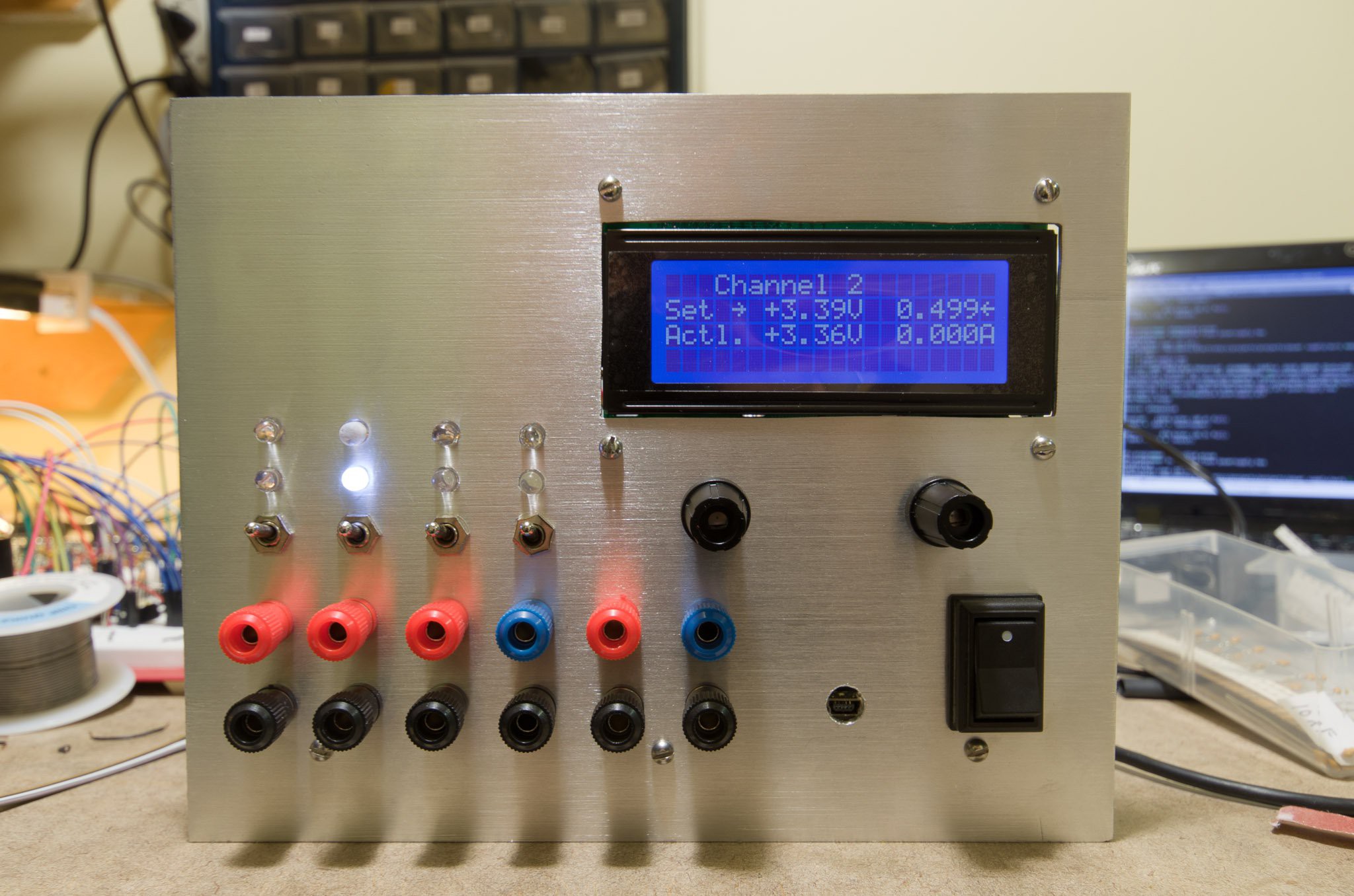
Control Board + First Channel Working (Video!)
05/29/2015 at 02:44 • 0 commentsTonight I got the first channel (confusingly mapped to Channel 2, but I have my reasons for this) up and running with the control board. To my utter surprise, the DACs still appear to work, despite having been subjected to 10V for 5 - 10 seconds (when I let the magic smoke out of the AVR). Yay for Microchip! :-) I have not done any accuracy testing on them, so I may still need to replace them if the output voltage is not as accurate as it should be, but for now things look to be pretty good.
Below is a video, followed by some images of the supply in action.
Voltage set with no load:
![]()
Shorting the outputs to show current limiting:
![]()
-
Display is Not Dead!
05/26/2015 at 14:48 • 6 commentsI was worried that the 10V magic smoke adventure from the weekend had killed my display... a quick test showed that it worked, but I didn't do much more than 5 seconds to see if it showed something.
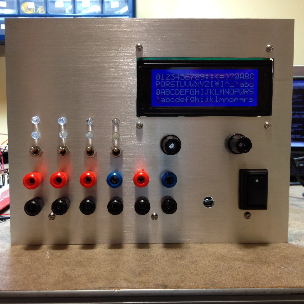
Last night, after re-soldering the entire controller board for a third time, (this time verifying the operation of the linear regulators before soldering them on), I was able to verify that the display works. There are still some problems somewhere; I suspect the issue is the DACs (which, given that they are MSSOP-10, I have been unable to verify without soldering onto the board), but I uploaded a simple display test program (seen below) and you can see that all characters are showing properly with no errors or artifacts.
![]()
Tonight I hope to have time to verify (and replace if needed) the DACs, and (finally) get the controller working.
One more note on the ISP issues: on this go-round, I decided to not populate the pullups / caps / TVS diodes on the encoders (which are shared with ISP pins). Those are the root cause of the ISP problems, and instead of putting them on the board I can solder them directly to the encoders. It is a bit more annoying, but perfectly doable, and will allow me to re-flash using the ISP if needed in the future.
Cheers
-
Rear Faceplate and Magic Smoke
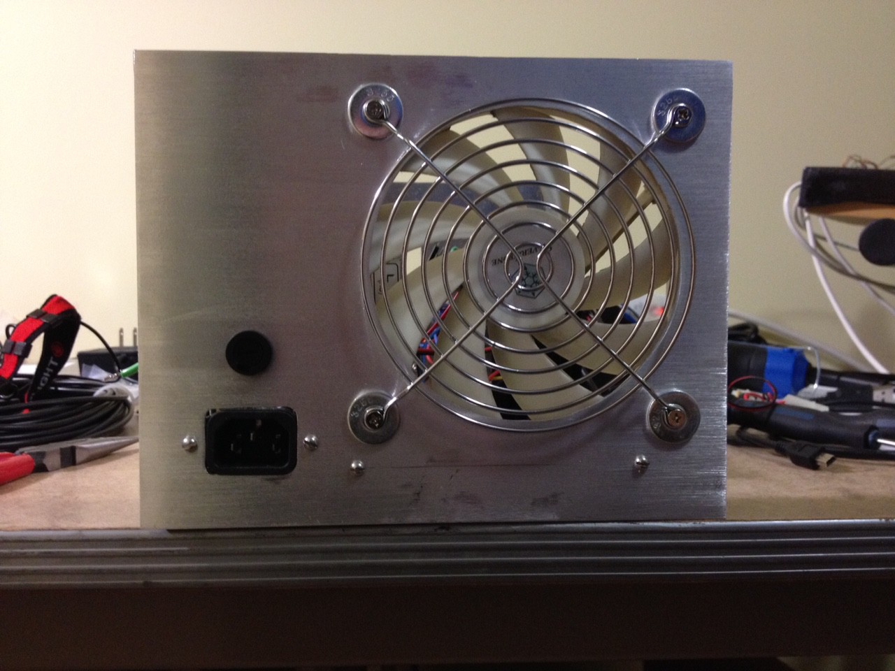
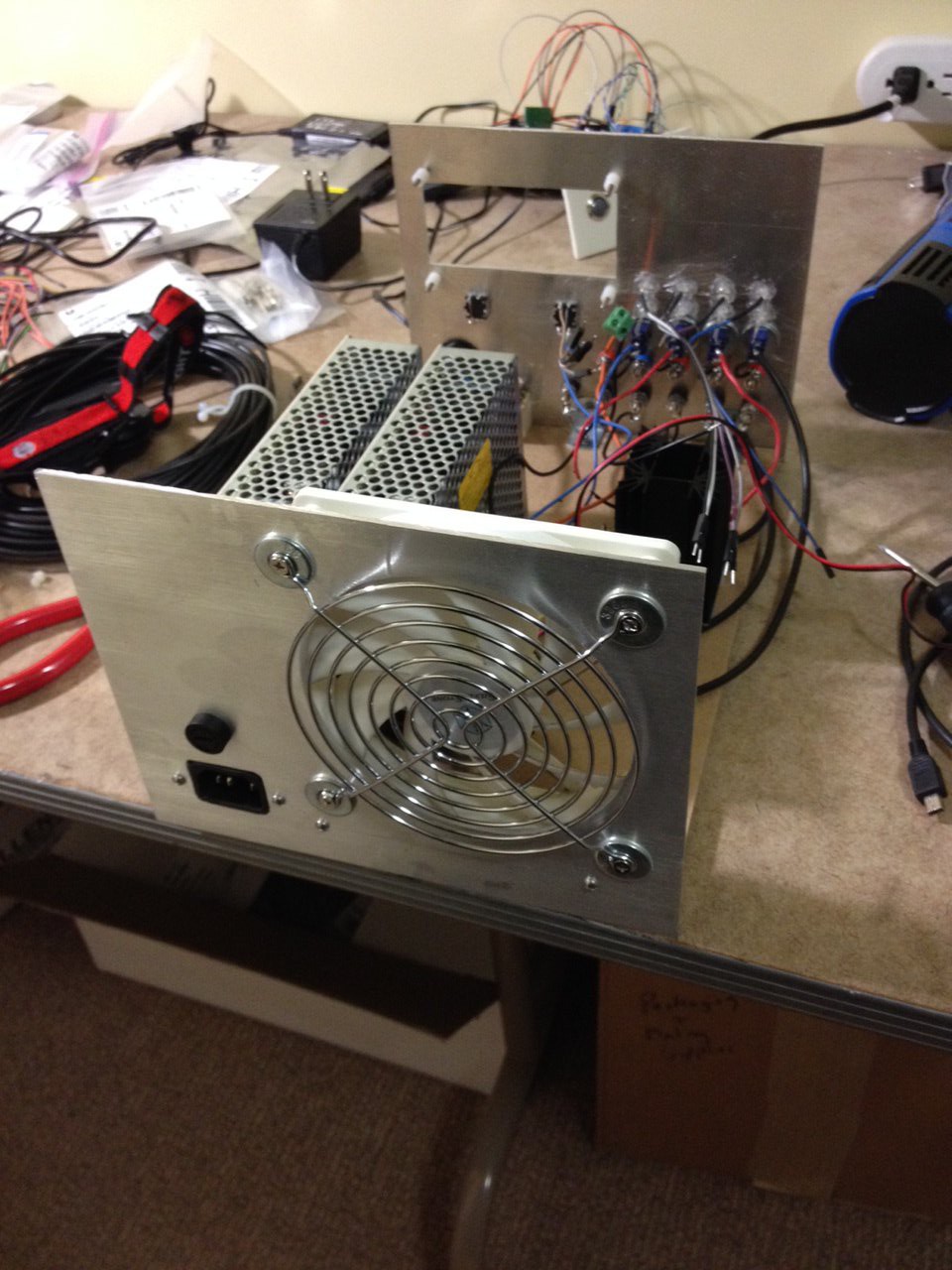
05/25/2015 at 16:19 • 0 commentsI finished the rear faceplate, and have the A/C hooked up and verified:
![]()
![]()
Unfortunately, when I plugged the controller (microcontroller + DAC + display) in, I let the magic smoke out.
It appears the problem was due to a faulty 7805 regulator which I had salvaged from who knows where. The regulator output 10v instead of 5v... which obviously didn't do so well for the AVR. The display has (luckily) appeared to survive (although I have only done some minimal testing with it, so there is still a chance that it is bad). I am unsure whether the DACs survived or not; I know that at least one channel on one of them is outputting the correct voltage, but without a working AVR I can't really set the voltage for any of the other ones.
My plan is to solder up yet another controller board, and this time test my regulators before I use them. Hopefully I will have time for that in the next few days.
Cheers
-
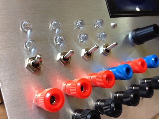
More Faceplate Work
05/23/2015 at 03:59 • 0 commentsI finished the remaining holes, sanded everything for a 'brushed aluminum' look, and mounted the hardware. Next step is the rear faceplate + all the wiring.
![]()
![]()
Bench Power Supply
Designing an open source, modular bench power supply to rule them all.