Christoph
-
PlatformIO
05/04/2019 at 19:23 • 0 commentsI installed VSCode and the PlatformIO extension to see if this board can be used with pio. It works!
Steps to reproduce:
Project setup
- in PlatformIO home tab, import Project Examples - stm32cube-hal-blink
- modify platformio.ini to have the following content (it might be ok to omit some settings, I'm not sure):
[env:demo_f030f4]
;platform = ststm32
platform = https://github.com/platformio/platform-ststm32.git
framework = stm32cube
board = demo_f030f4
build_flags = -DF0
; change microcontroller
board_build.mcu = stm32f030f4p6
; change MCU frequency
board_build.f_cpu = 48000000L
upload_protocol = stlink
Just using "ststm32" as platform doesn't work because there's a problem with the F030F4 startup code, see issue here: https://github.com/platformio/platform-ststm32/issues/234. So we need the github platform. - Main already has blink code, but this breakout board's LED is connected to GPIO port B, pin 1. So change the port settings to (also pay attention to the clock enable macro, which needs to be changed to port B, too):
#define LED_PIN                                GPIO_PIN_1
#define LED_GPIO_PORT                          GPIOB
#define LED_GPIO_CLK_ENABLE()                  __HAL_RCC_GPIOB_CLK_ENABLE()
(somewhere around line 24)
Hardware setup
Connect an ST-Link to the breakout board and supply 3.3 V to VDD (the ST-Link connection will not supply power!). See here: https://hackaday.io/project/4277/gallery#52043e53586461bb2bbb51046f9c2334
Build and upload
should work out of the box. If upload fails, check udev rules and dialout group stuff as described here: https://docs.platformio.org/en/latest/plus/debug-tools/stlink.html#debugging-tool-stlink
Sometimes replugging the USB cable or a manual reset can also be helpful.
-
Updated repo
12/02/2015 at 12:34 • 0 commentsI added the current gerbers (pcb with BOOT0 pulldown) to the github repo
-
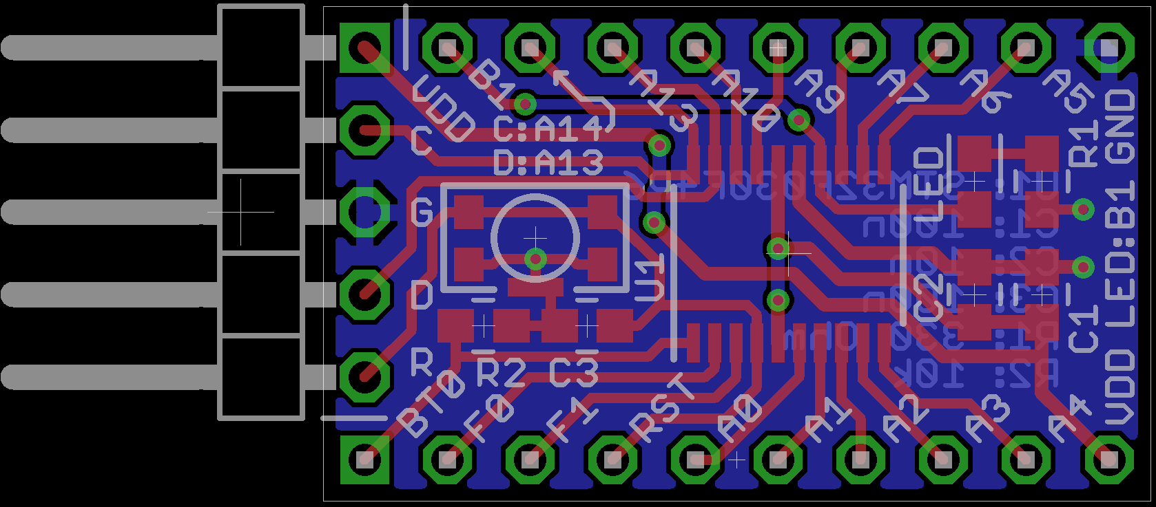
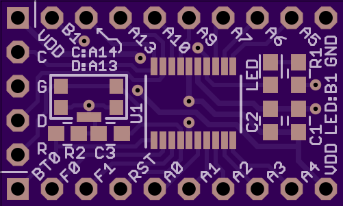
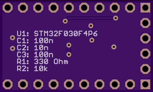
Layout revised
11/09/2015 at 14:16 • 0 commentsI added a BOOT0 pull-down resistor (10k) to the schematic and layout and also made some more minor layout tweaks. Silk screen type size could be increased a bit to 35 mil (was about 30 mil before) and I also increased the supply trace width as suggested in the comments.
![]()
Not tested yet, but if you want to try it:
https://oshpark.com/shared_projects/WwATL5iu
![]()
![]()
-
BOOT0 issue
11/04/2015 at 09:10 • 0 commentsAs david pointed out in the comments, BOOT0 should be pulled low to boot the application. For now this has to be done on the breadboard because the PCB doesn't include a pull-down resistor. I hope to fix this in the next PCB revision without having to use smaller (0402) parts.
-
Added eagle files to repo
07/13/2015 at 11:41 • 0 commentsI uploaded to the eagle (6.6) brd and sch files to the repo. Happy whatevering!
-
Now on github
06/30/2015 at 07:43 • 0 commentsYesterday's work is now on github:
- Code::Blocks example project
- initialization code for the systick timer
- elapsedMillis class
- blinky code example
I'm thinking about writing a project wizard for creating libopencm3 based projects in Code::Blocks, which shouldn't be too hard.
-
This board, Code::Blocks and libopencm3
06/29/2015 at 13:16 • 1 commentI tried to set up Code::Blocks to use libopencm3, which was not that hard, after all. It's just a lot of work, but it can be stored as a template! This post might appear to be very long, but about 90% of it are screenshots, and cut 'n paste code.
Sources of information
- Compiler and library readme. I'm using GCC ARM Embedded 4.9-2015-q2-update
- Code::Blocks forum and wiki (for setting up the compiler)
- libopencm3 wiki and examples
First of all I downloaded and compiled libopencm3 according to their instructions, with a custom destination directory. This left me with a set of chip libraries (opencm3_stm32f0 and many more for other chips) to be included in my project. I also have the compiler configured already. So here are a few screenshots of my C::B setup.
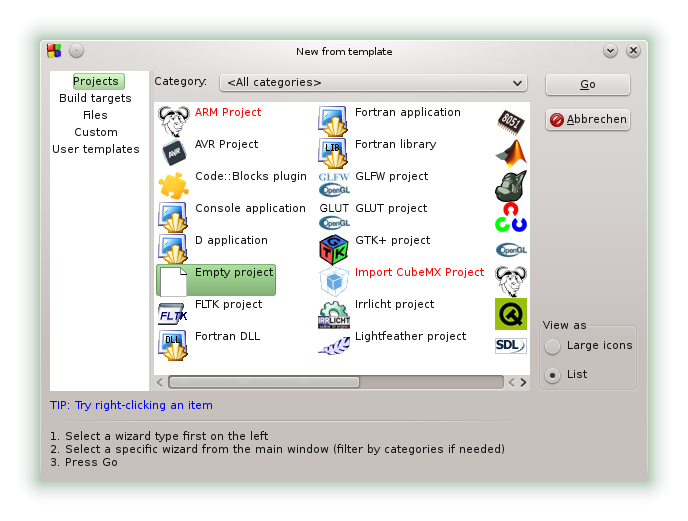
Create an empty project (File->New->Project):
![]()
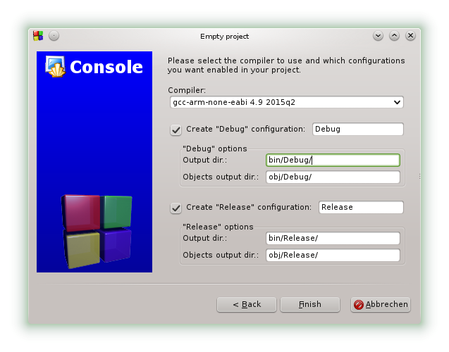
Hit go and enter your project's title and filename. Select your arm-none-eabi-gcc when asked for a compiler, and hit finish (this automatically creates debug and release configurations):
Fine, there's now an empty project in the workspace that we can fill with our source code and build info.![]()
Code
Create a main.cpp (File->New->Empty File or CTRL-Shift-N) and add it to the project. Mine looks like this (based on code taken from one of the STM32F0 examples from https://github.com/libopencm3/libopencm3-examples/blob/master/examples/stm32/f0/stm32f0-discovery/systick_blink/systick_blink.c):
#include <libopencm3/stm32/rcc.h>
#include <libopencm3/stm32/gpio.h>
#include <libopencm3/cm3/nvic.h>
#include <libopencm3/cm3/systick.h>

/* PB1 is connected to the onboard LED on the STM32F030F4P6 breakout board. */
#define PORT_LED_ONBOARD GPIOB
#define PIN_LED_ONBOARD GPIO1

/* Called when systick fires */
void sys_tick_handler(void)
{
	gpio_toggle(PORT_LED_ONBOARD, PIN_LED_ONBOARD);
}

/* Set up timer to fire freq times per second */
static void systick_setup(int freq)
{
	systick_set_clocksource(STK_CSR_CLKSOURCE_AHB);
	/* clear counter so it starts right away */
	STK_CVR = 0;

	systick_set_reload(rcc_ahb_frequency / freq);
	systick_counter_enable();
	systick_interrupt_enable();
}

/* set STM32 to clock by 48MHz from HSI oscillator */
static void clock_setup(void)
{
	rcc_clock_setup_in_hsi_out_48mhz();

	/* Enable clocks to the GPIO subsystems */
	rcc_periph_clock_enable(RCC_GPIOB);
}

static void gpio_setup(void)
{
	gpio_mode_setup(PORT_LED_ONBOARD, GPIO_MODE_OUTPUT, GPIO_PUPD_NONE, PIN_LED_ONBOARD);
}

int main(void)
{
	clock_setup();
	gpio_setup();

	/* setup systick to generate 2 LED flashes per second */
	systick_setup(4);

	/* Do nothing in main loop */
	while (1);
}
Compiler and Linker flags
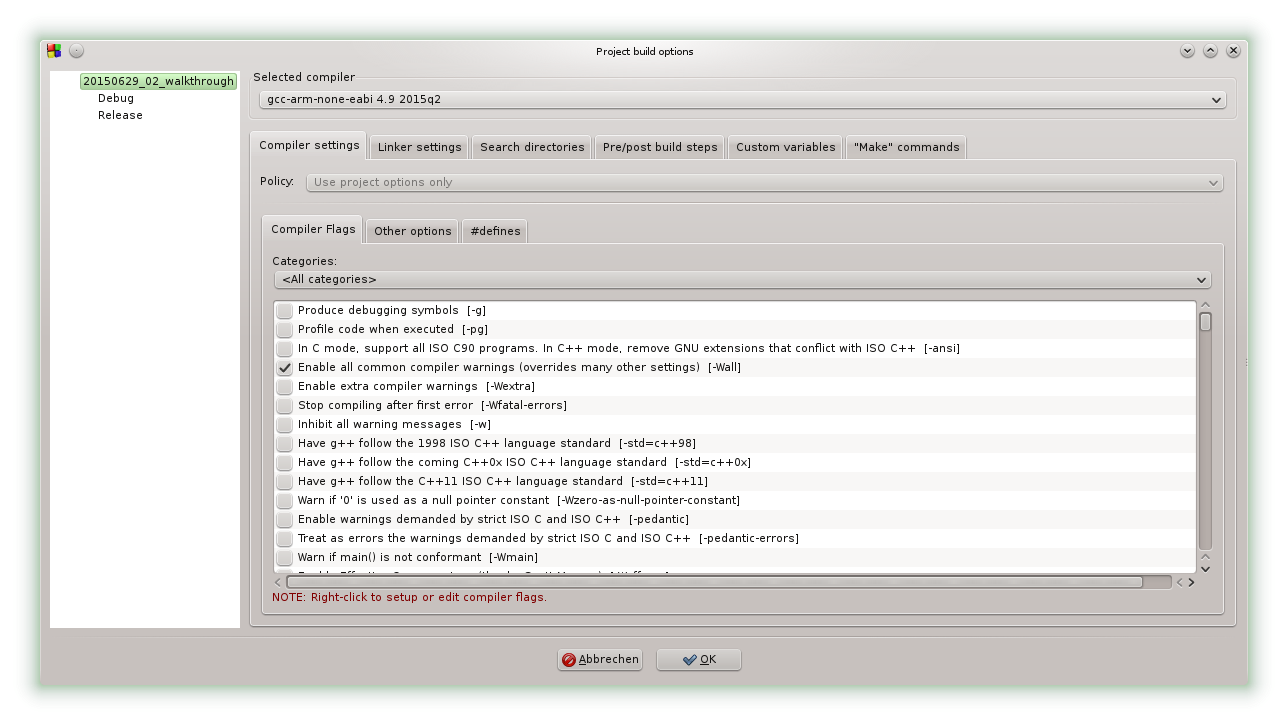
Now comes the trickier part: Set up flags for the compiler and the linker. Go to Project->Build options and select the top-level entry, which has options for all sub-targets (debug and release):
![]()
My compiler flags in the "Compiler Settings" tab, combined from the tabs "Compiler Flags" and "Other options", are:
-Wall
-pedantic
-mlittle-endian
-msoft-float
-mthumb
-mcpu=cortex-m0
-ffunction-sections
-fdata-sections
-fno-exceptions
and one define in the "#defines" tab:STM32F0
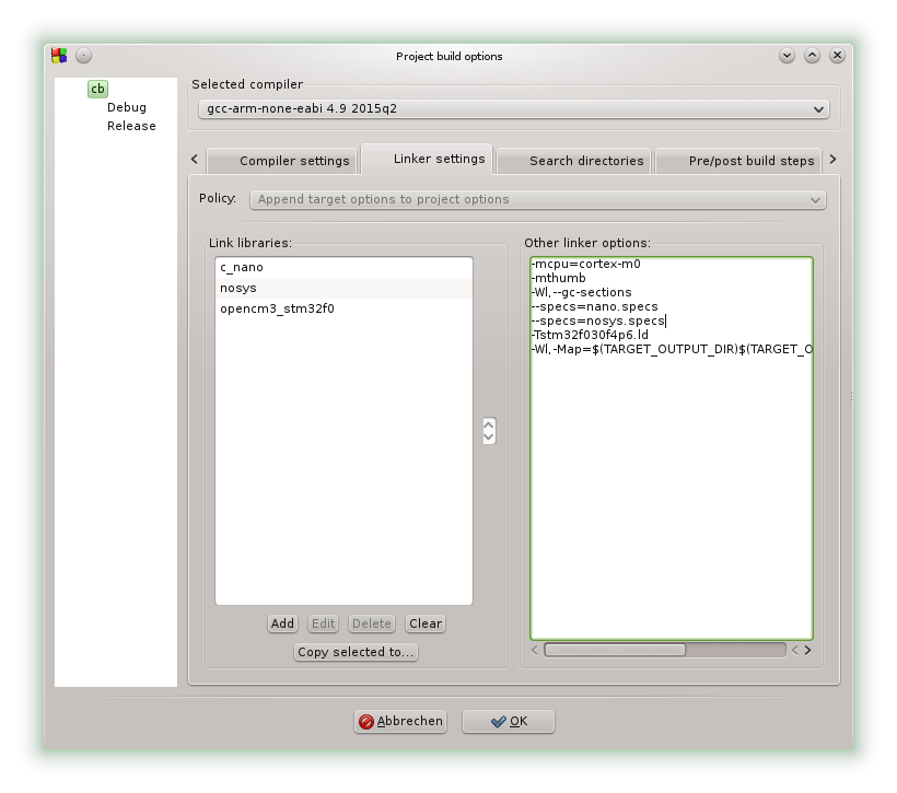
Now for the linker ("Linker settings" tab):![]()
That is in the "Link libraries" list:
c_nano
nosys
opencm3_stm32f0
and in the "Other linker options":-mcpu=cortex-m0 -mthumb -Wl,--gc-sections --specs=nano.specs --specs=nosys.specs -Tstm32f030f4p6.ld -Wl,-Map=$(TARGET_OUTPUT_DIR)$(TARGET_OUTPUT_BASENAME).map,--cref
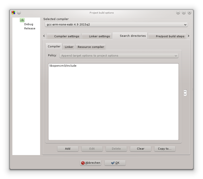
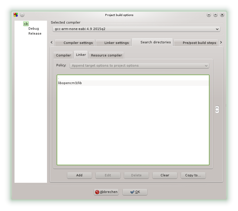
Search Directories for the compiler:
(this requires libopencm3 to be in the project root directory)![]()
For the linker:
The first entry in the search directory list is just a dot, so the linker will find a linker script in the project root directory. The other entry is a relative path to the pre-built libraries for all chips.![]()
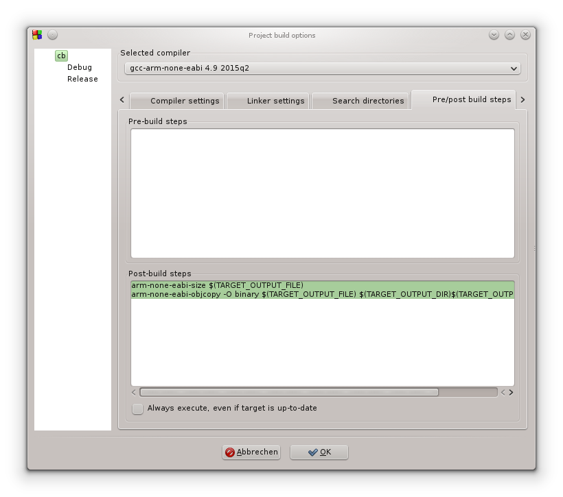
We're almost there, just some fine-tuning after the build is finished:
![]()
arm-none-eabi-size $(TARGET_OUTPUT_FILE)
arm-none-eabi-objcopy -O binary $(TARGET_OUTPUT_FILE) $(TARGET_OUTPUT_DIR)$(TARGET_OUTPUT_BASENAME).bin
Now you can also add extra flags for debug and release builds (generate debugging symbols, or strip symbols and optimize, whatever you need).Linker script
This was a bit harder, because libopencm3 has some kind of automatic linker script generation magic built in. I couldn't use that from within Code::Blocks, so I cobbled together my own from their template and chip data file. Note that I did this without any notable experience with linker scripts, I just try and see what happens.
This one worked indeed, because blinky.
stm32f030f4p6.ld in the project root directory:
MEMORY
{
	rom (rx) : ORIGIN = 0x08000000, LENGTH = 16K
	ram (rwx) : ORIGIN = 0x20000000, LENGTH = 4K
}

/* Enforce emmition of the vector table. */
EXTERN (vector_table)

/* Define the entry point of the output file. */
ENTRY(reset_handler)

/* Define sections. */
SECTIONS
{
	.text : {
		*(.vectors)	/* Vector table */
		*(.text*)	/* Program code */
		. = ALIGN(4);
		*(.rodata*)	/* Read-only data */
		. = ALIGN(4);
	} >rom

	/* C++ Static constructors/destructors, also used for __attribute__
	 * ((constructor)) and the likes */
	.preinit_array : {
		. = ALIGN(4);
		__preinit_array_start = .;
		KEEP (*(.preinit_array))
		__preinit_array_end = .;
	} >rom
	.init_array : {
		. = ALIGN(4);
		__init_array_start = .;
		KEEP (*(SORT(.init_array.*)))
		KEEP (*(.init_array))
		__init_array_end = .;
	} >rom
	.fini_array : {
		. = ALIGN(4);
		__fini_array_start = .;
		KEEP (*(.fini_array))
		KEEP (*(SORT(.fini_array.*)))
		__fini_array_end = .;
	} >rom

	/*
	 * Another section used by C++ stuff, appears when using newlib with
	 * 64bit (long long) printf support
	 */
	.ARM.extab : {
		*(.ARM.extab*)
	} >rom
	.ARM.exidx : {
		__exidx_start = .;
		*(.ARM.exidx*)
		__exidx_end = .;
	} >rom

	. = ALIGN(4);
	_etext = .;

	.data : {
		_data = .;
		*(.data*)	/* Read-write initialized data */
		. = ALIGN(4);
		_edata = .;
	} >ram AT >rom
	_data_loadaddr = LOADADDR(.data);

	.bss : {
		*(.bss*)	/* Read-write zero initialized data */
		*(COMMON)
		. = ALIGN(4);
		_ebss = .;
	} >ram

	/*
	 * The .eh_frame section appears to be used for C++ exception handling.
	 * You may need to fix this if you're using C++.
	 */
	/** DISCARD/ : { *(.eh_frame) } */

	. = ALIGN(4);
	end = .;
}

PROVIDE(_stack = ORIGIN(ram) + LENGTH(ram));
Note that the .eh_frame section is not discarded (it is by default).Hit build (or CTRL+F9) and you should be rewarded with binaries in the target/bin directory. You can now program your target board with the programmer of your choice. It's also possible to include the programming in the post-build steps or to configure it as a tool to be accessed in the C::B tools menu.
I hope this helps some people!
-
SSD1351 Display and uGFX
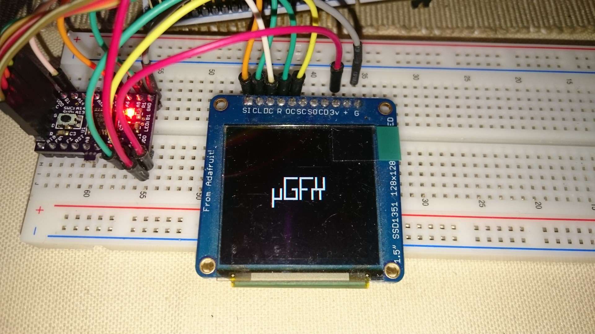
06/18/2015 at 21:45 • 0 commentsThis was fairly easy - I added the uGFX sources to my project and after rearranging some include directives it actually compiled fine. uGFX also comes with some pre-written display drivers, including one for the SSD1351. The only thing I had to customize was the board file template:
#include "gpio.h" // <- generated by CubeMX
#include "spi.h"// <- generated by CubeMX

#define PORT_OLED_RESET GPIOA
#define PIN_OLED_RESET GPIO_PIN_3
#define PORT_OLED_CS GPIOA
#define PIN_OLED_CS GPIO_PIN_4
#define PORT_OLED_DC GPIOB
#define PIN_OLED_DC GPIO_PIN_1

static inline void init_board(GDisplay *g) {
  (void) g;
  HAL_GPIO_WritePin(PORT_OLED_RESET, PIN_OLED_RESET, GPIO_PIN_SET);
  HAL_GPIO_WritePin(PORT_OLED_CS, PIN_OLED_CS, GPIO_PIN_SET);
  HAL_GPIO_WritePin(PORT_OLED_DC, PIN_OLED_DC, GPIO_PIN_SET);
}

static inline void setpin_reset(GDisplay *g, bool_t state) {
  (void) g;
  if (state)
    HAL_GPIO_WritePin(PORT_OLED_RESET, PIN_OLED_RESET, GPIO_PIN_RESET);
  else
    HAL_GPIO_WritePin(PORT_OLED_RESET, PIN_OLED_RESET, GPIO_PIN_SET);
}

static inline void acquire_bus(GDisplay *g) {
  HAL_GPIO_WritePin(PORT_OLED_CS, PIN_OLED_CS, GPIO_PIN_RESET);
}

static inline void release_bus(GDisplay *g) {
  HAL_GPIO_WritePin(PORT_OLED_CS, PIN_OLED_CS, GPIO_PIN_SET);
}

static inline void write_cmd(GDisplay *g, uint8_t index) {
  (void) g;
  HAL_GPIO_WritePin(PORT_OLED_DC, PIN_OLED_DC, GPIO_PIN_RESET);
  HAL_SPI_Transmit(&hspi1, &index, 1, HAL_MAX_DELAY);
  HAL_GPIO_WritePin(PORT_OLED_DC, PIN_OLED_DC, GPIO_PIN_SET);
}

static inline void write_data(GDisplay *g, uint8_t data) {
  (void) g;
  HAL_SPI_Transmit(&hspi1, &data, 1, HAL_MAX_DELAY);
}
There are some other empty functions in there, which are not needed and omitted in the above snippet. As you can see it's just a matter of setting the display's control pins and sending single bytes via SPI, which is easily done with ST's HAL. GPIO and SPI initialization code was generated by CubeMX and is called by main(), but it could also be added to the init_board() function.And it actually works:
![]()
uGFX without widgets (and everything that would come with them) takes about 6kB flash and a few hundred bytes (something between 300 and 400) of RAM. That includes one of uGFX's fonts stored in flash.
-
CubeMX 4.8.0
06/17/2015 at 19:00 • 0 commentsI just noticed that ST released CubeMX 4.8.0, so I gave it a try. I'm still running ubuntu 14.04, which already worked for CubeMX 4.6.0. The software is zipped when you download it, so I just unzipped the installer (an exe archive) and ran it:
sudo java -jar SetupSTM32CubeMX-4.8.0.exe
Unfortunately, root permissions are necessary for running the installer.Then I selected a directory somewhere in my home folder and finished the installation without any problems. To run the installed program:
java -jar ~/path/to/CubeMX/installation/STM32CubeMX.exe
As already noted in my previous log, this line can be added as an alias (~/.bash_aliases):alias cubemx-4.6.0='java -jar ~/builds/STM32CubeMX_4.6.0/STM32CubeMX.exe' alias cubemx-4.8.0='java -jar ~/builds/STM32CubeMX_4.8.0/STM32CubeMX.exe' alias cubemx='cubemx-4.8.0'
Code generation still has two problems:- No startup code is included in the generated code and
- the included linker script is empty.
Those two are not terribly difficult to overcome, though, because both startup and linker scripts can be copied from the "repository" (a bunch of folders on your disk where CubeMX is taking all the source files from).
-
Just a small update
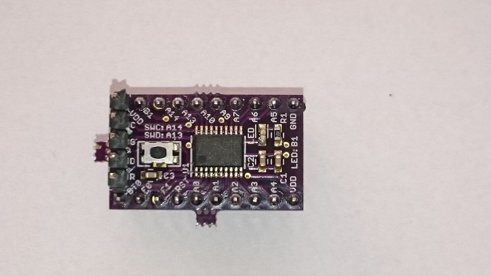
06/16/2015 at 20:13 • 0 commentsI actually found time to redesign my reflow oven controller and to assemble a test board with the new layout:
![]()
The extra clearance between the 0603 parts to the right really helps during assembly. The LED (an Osram SmartLED LA L296) is still a bit too bright with a 330 Ohm resistor.
I also updated the link to OSH Park.
STM32F030F4P6 breakout board
Not as bulky as the nucleo boards, after all.