Christoph
-
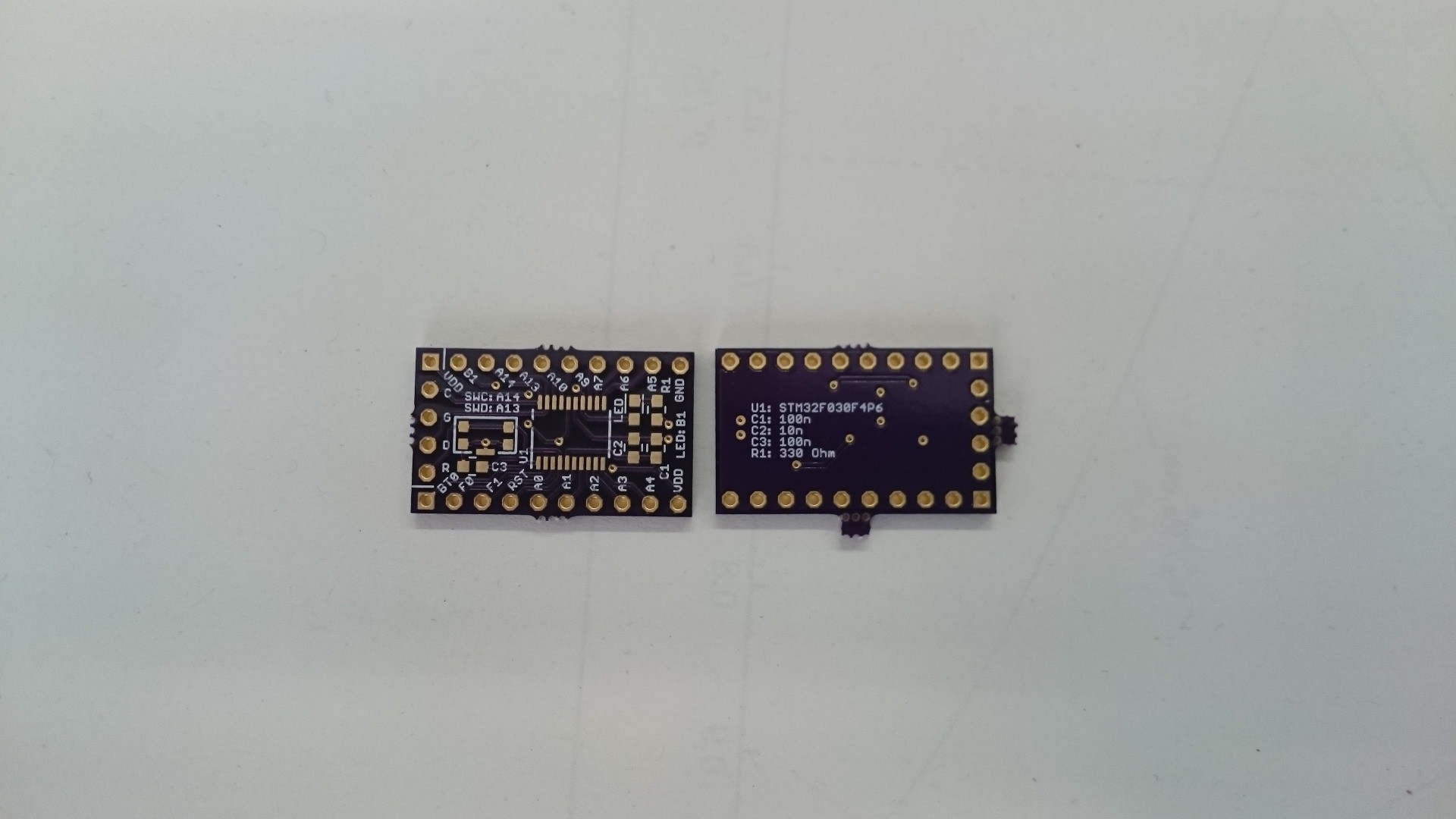
New boards have arrived
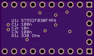
03/04/2015 at 11:31 • 0 commentsYay! Indeed, all labels are readable so I really didn't accidentally place any of them on top of vias and such:
![]()
Component list has been updated to include the reset line capacitor and increased value for the LED current limiting resistor.
-
Codebase
02/14/2015 at 23:06 • 0 commentsI don't really have a codebase for this board. I create a project in CubeMX, configure the peripherals and clock, and generate the code. All the small gaps in there must be filled later. Let's have a look at the CubeMX part first, followed by the gcc flags.
CubeMX
My computer is running Ubuntu 14.04. CubeMX is written for windows, but I didn't have any problems yet. The installer is an archive, and can be executed with java:
java -jar SetupSTM32CubeMX-4.6.0.exe
You might need root permissions for installing, but not for executing the software later. Install where you like, I installed it somewhere in my home directory.To run:
java -jar ~/path/to/CubeMX/installation/STM32CubeMX.exe
this is also in my bash aliases.Warning: CubeMX 4.5.0 had path problems ("/" vs "\"), 4.6.0 seems to behave better in this respect.
Now that CubeMX is running, we can configure our chip, clocks, peripherals. Code generation is the next crucial step. Here are my project settings:
- project tab:
- Toolchain/IDE: TrueSTUDIO 4.3.1
- Toolchain/IDE: TrueSTUDIO 4.3.1
- code generator tab:
- Copy all used libraries into the project folder
- Generate peripheral initialization as a pair of '.c/.h' files per IP
- Keep user code when re-generating
- Delete previously generated files when not re-generated
A note about "keep user code": This apparently doesn't include the linker script. CubeMX will, however, generate an empty linker script for the STM32F030F4P6. Once I filled it with content, it got erased after I re-generated the project. So if you write a linker script, store it in a place where CubeMX will not touch it.
gcc
- Compiler:
-Wall
-mlittle-endian
-mthumb
-Os
-mcpu=cortex-m0
-ffunction-sections
-fdata-sections
-fno-exceptions
-flto
-DSTM32F030x6
The last define might be a bit surprising, but it's actually the correct one for this subfamily. - Linker:
-TSTM32F030F4_FLASH.ld
-mcpu=cortex-m0
-mthumb
-Wl,--gc-sections
--specs=nano.specs
--specs=nosys.specs
-Os
-flto
-lc_nano
-lnosys
The linker script might be of interest:
ENTRY(Reset_Handler)

/* Highest address of the user mode stack */
_estack = 0x20000FFF;    /* end of RAM */

/* Generate a link error if heap and stack don't fit into RAM */
_Min_Heap_Size = 0x200;      /* required amount of heap  */
_Min_Stack_Size = 0x400; /* required amount of stack */

/* Specify the memory areas */
MEMORY
{
FLASH (rx)      : ORIGIN = 0x8000000, LENGTH = 16K
RAM (xrw)      : ORIGIN = 0x20000000, LENGTH = 4K
}

/* Define output sections */
SECTIONS
{
  /* The startup code goes first into FLASH */
  .isr_vector :
  {
    . = ALIGN(4);
    KEEP(*(.isr_vector)) /* Startup code */
    . = ALIGN(4);
  } >FLASH

  /* The program code and other data goes into FLASH */
  .text :
  {
    . = ALIGN(4);
    *(.text)           /* .text sections (code) */
    *(.text*)          /* .text* sections (code) */
    *(.glue_7)         /* glue arm to thumb code */
    *(.glue_7t)        /* glue thumb to arm code */
    *(.eh_frame)

    KEEP (*(.init))
    KEEP (*(.fini))

    . = ALIGN(4);
    _etext = .;        /* define a global symbols at end of code */
  } >FLASH

  /* Constant data goes into FLASH */
  .rodata :
  {
    . = ALIGN(4);
    *(.rodata)         /* .rodata sections (constants, strings, etc.) */
    *(.rodata*)        /* .rodata* sections (constants, strings, etc.) */
    . = ALIGN(4);
  } >FLASH

  .ARM.extab   : { *(.ARM.extab* .gnu.linkonce.armextab.*) } >FLASH
  .ARM : {
    __exidx_start = .;
    *(.ARM.exidx*)
    __exidx_end = .;
  } >FLASH

  .preinit_array     :
  {
    PROVIDE_HIDDEN (__preinit_array_start = .);
    KEEP (*(.preinit_array*))
    PROVIDE_HIDDEN (__preinit_array_end = .);
  } >FLASH
  .init_array :
  {
    PROVIDE_HIDDEN (__init_array_start = .);
    KEEP (*(SORT(.init_array.*)))
    KEEP (*(.init_array*))
    PROVIDE_HIDDEN (__init_array_end = .);
  } >FLASH
  .fini_array :
  {
    PROVIDE_HIDDEN (__fini_array_start = .);
    KEEP (*(SORT(.fini_array.*)))
    KEEP (*(.fini_array*))
    PROVIDE_HIDDEN (__fini_array_end = .);
  } >FLASH

  /* used by the startup to initialize data */
  _sidata = LOADADDR(.data);

  /* Initialized data sections goes into RAM, load LMA copy after code */
  .data :
  {
    . = ALIGN(4);
    _sdata = .;        /* create a global symbol at data start */
    *(.data)           /* .data sections */
    *(.data*)          /* .data* sections */

    . = ALIGN(4);
    _edata = .;        /* define a global symbol at data end */
  } >RAM AT> FLASH


  /* Uninitialized data section */
  . = ALIGN(4);
  .bss :
  {
    /* This is used by the startup in order to initialize the .bss secion */
    _sbss = .;         /* define a global symbol at bss start */
    __bss_start__ = _sbss;
    *(.bss)
    *(.bss*)
    *(COMMON)

    . = ALIGN(4);
    _ebss = .;         /* define a global symbol at bss end */
    __bss_end__ = _ebss;
  } >RAM

  /* User_heap_stack section, used to check that there is enough RAM left */
  ._user_heap_stack :
  {
    . = ALIGN(4);
    PROVIDE ( end = . );
    PROVIDE ( _end = . );
    . = . + _Min_Heap_Size;
    . = . + _Min_Stack_Size;
    . = ALIGN(4);
  } >RAM
}
I actually took a linker script from the CubeMX repo that was written for a bigger chip and I simply adjust flash and ram size. I'm not sure if this is correct!
- project tab:
-
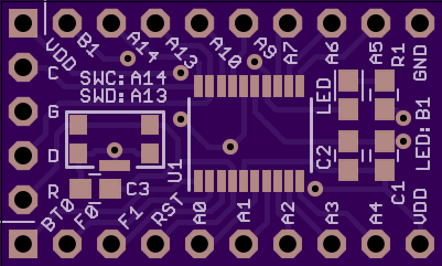
New Layout is done, waiting...
02/10/2015 at 22:36 • 2 commentsAfter I figured out the flaws in the current layout it was fairly easy to take care of them. The new layout has exactly the same size and pinout as the old one, but
- moved silk screen labels further away from SWD header,
- smaller silk screen text for more labels and hints,
- no more silk screen above vias,
- added reset cap,
- moved LED, resistor, and decoupling caps further away from each other for easier assembly (other parts got pushed around while placing them with my tweezers),
- changed LED current limiting resistor to 330 ohm,
- updated bottom silk screen,
- added labels for the connections SWDCLK - PA14, SWDIO - PA13, and LED - PB1.
Preview:
![]()
![]()
-
Printing ADC values over UART
02/10/2015 at 20:44 • 2 comments![]() Sounds simple? Not quite. The available flash is very limited, so fancy stuff like snprintf() simply won't fit - at least with the newlib I'm using. I'm really not sure how newlib has been built (to be honest I'm not even sure if I did it myself and screwed it up) and if I could trim it a bit.
Sounds simple? Not quite. The available flash is very limited, so fancy stuff like snprintf() simply won't fit - at least with the newlib I'm using. I'm really not sure how newlib has been built (to be honest I'm not even sure if I did it myself and screwed it up) and if I could trim it a bit. itoa() maybe? No sign of it.
But I just wanted to see the ADC work and wrote a simple conversion from uint8_t to ascii, which is quick, easy and won't use huge amounts of flash.The ADC is very simple to set up using CubeMX. I've set it to 8 bits, right aligned, continuous conversion mode, overrun data (i.e. discard previous value once a conversion has finished). Every thing I had to add was
- starting the ADC
- reading values from it
MX_ADC_Init(); // <- actually added by CubeMX
HAL_ADC_Start(&hadc);
// Other peripherals ommitted
while(1)
{
  HAL_UART_Transmit(&huart1, "ADC: 0x", 7, HAL_MAX_DELAY);

  uint8_t adc = HAL_ADC_GetValue(&hadc);
  // convert to hex string
  uint8_t nibble;
  char c;
  nibble = (adc >> 4) & 0x0F;
  if (nibble > 9)
  {
    c = 'A' + nibble - 0xA;
  }
  else
  {
    c = '0' + nibble;
  }
  HAL_UART_Transmit(&huart1, &c, 1, HAL_MAX_DELAY);
  nibble = (adc >> 0) & 0x0F;
  if (nibble > 9)
  {
    c = 'A' + nibble - 0xA;
  }
  else
  {
    c = '0' + nibble;
  }
  HAL_UART_Transmit(&huart1, &c, 1, HAL_MAX_DELAY);
  HAL_UART_Transmit(&huart1, "\r", 1, HAL_MAX_DELAY);
  HAL_Delay(100);
}
Surely not the most effective code, but it does the job. A "nibble to ascii" function would certainly make it more readable. DMA should also be easy.
Now the 10k pot, connected as a voltage divider, can "just be read".
After all I've read about CubeMX, it's surprisingly not-that-bad. Writing code for simple tasks like this is just as easy as writing for arduino platforms. Sure, there might be bugs in ST's HAL, but I'm to my knowledge that's also true for arduino.
-
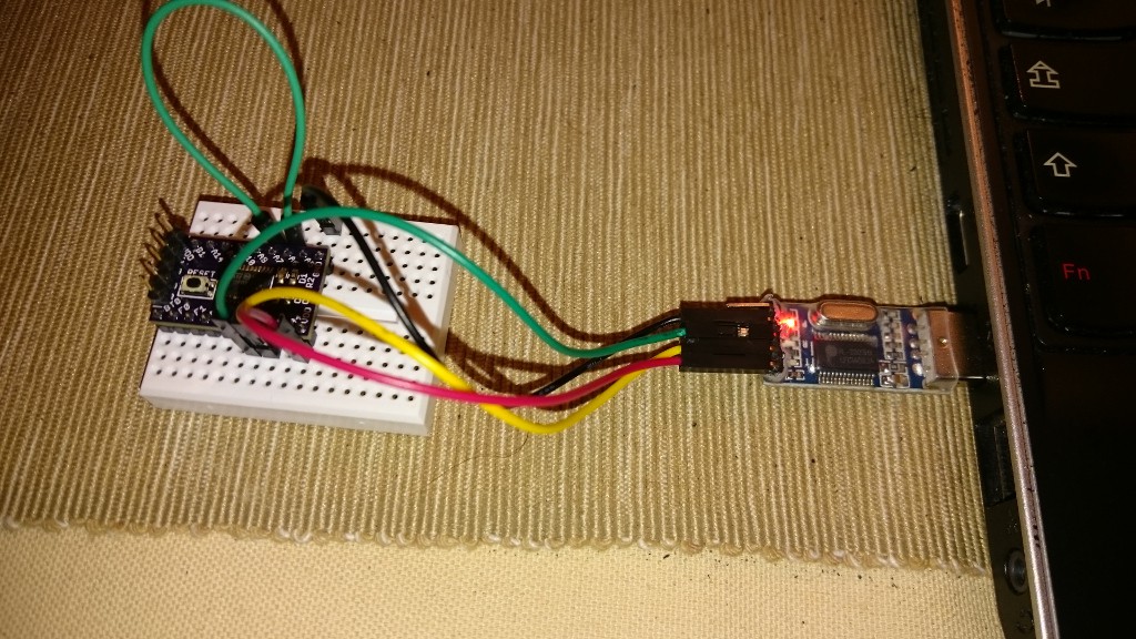
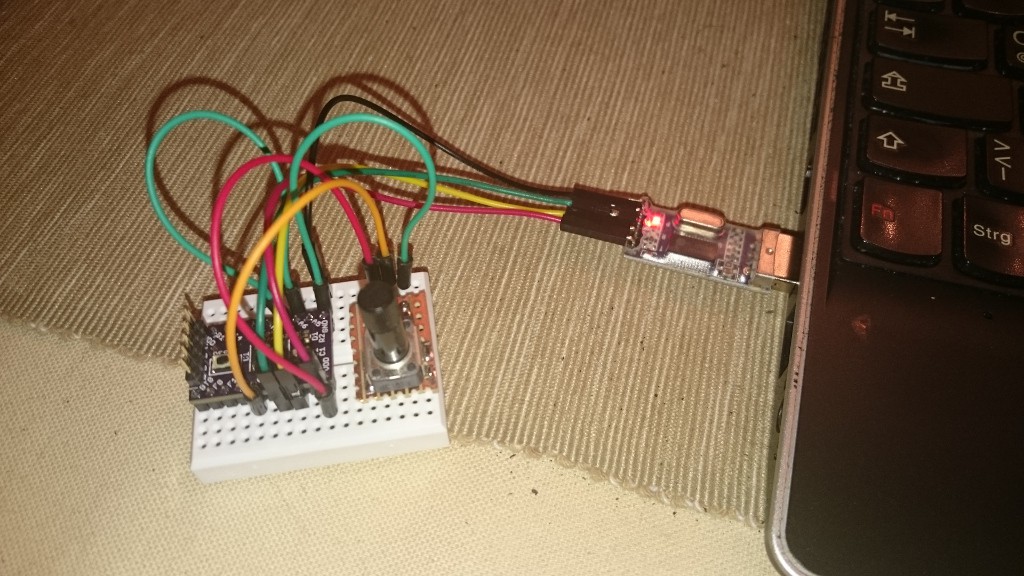
SPI and UART are working
02/09/2015 at 23:21 • 0 commentsWrote a simple SPI loopback test and a logic level <-> USB Serial device is showing correct output. Neat! ST's hardware abstraction layer seems a bit odd, though. For example they seem to mix "UART" and "USART" in many places, making it hard to decide which function is correct. Other than that, it's been quite easy.
![]()
The STM32F0 is powered by the USB adapter.
-
The reset line is missing a cap, and silkscreen problems
02/09/2015 at 19:24 • 0 commentsFor the next board revision I'll have to remember to put a cap between reset and ground. Reset has a weak internal pullup resistor, so I can at least omit that I think.
One other detail that's annoying me is that the silk screen is of course broken on top of any holes. I'll try to move any text away from them to keep it readable.
The SWD signal names are covered by those small connector housings, so moving them a bit further inwards might be a good idea.
-
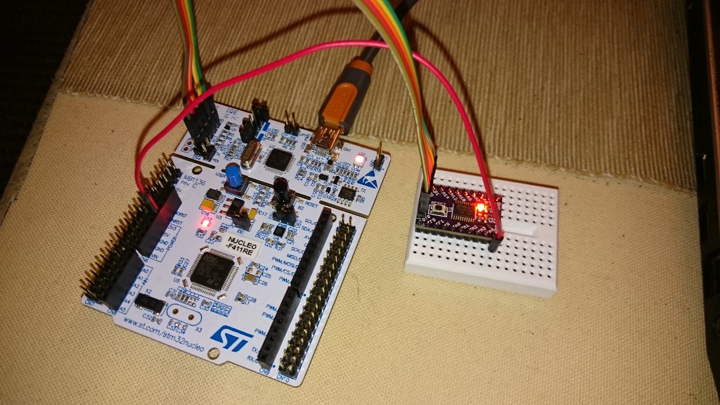
Tested the first two boards and they work
02/09/2015 at 19:19 • 0 commentsFirst of all, just connecting the SWD wires doesn't do the trick. The nucleo's SWD header cannot supply power to an external target, it will just sense it (if I'm reading the schematic correctly). So an extra 3.3V wire must be added from one of the 3.3V pins on the nucleo board to the breakout board's VDD pin.
I also had to unplug/plug the nucleo board's USB cable before it would let me program the chip with blinky code, but now it runs:
![]()
The LED is too bright. I used a 180 ohm resistor, so 330 ohm should be sufficient.
STM32F030F4P6 breakout board
Not as bulky as the nucleo boards, after all.
 Sounds simple? Not quite. The available flash is very limited, so fancy stuff like snprintf() simply won't fit - at least with the newlib I'm using. I'm really not sure how newlib has been built (to be honest I'm not even sure if I did it myself and screwed it up) and if I could trim it a bit.