Kert
Kert-
First electronics test components arriving
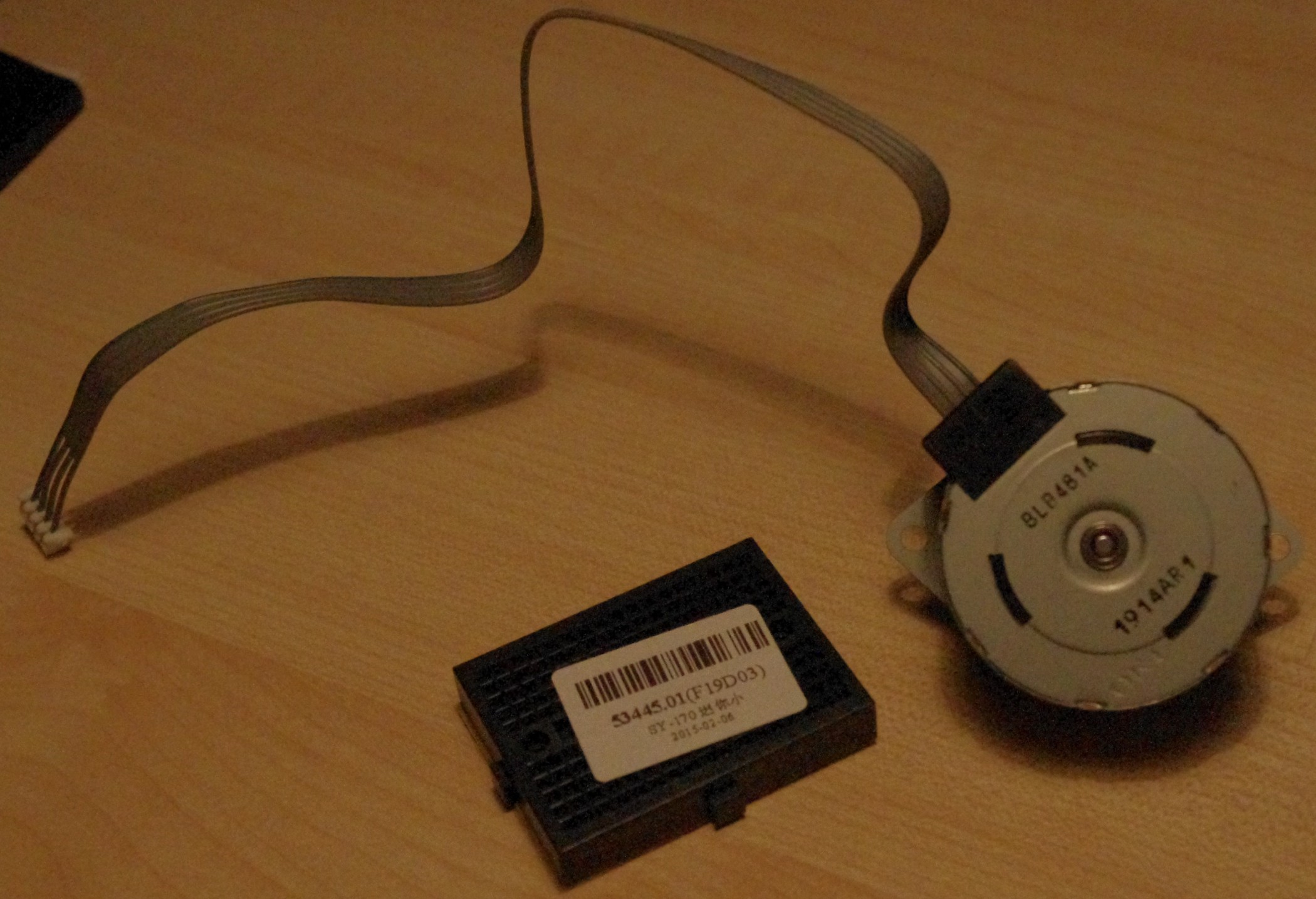
02/18/2015 at 17:03 • 0 commentsIt seems first of the packets I ordered on 5th Feb for assessing the viability of what I have in mind electronics wise have started arriving. Some of these items arriving I can use also for the machine. Not the stepper motor on the picture though, that one is purely for testing the electronics and my ability to drive it with the components I want to. The stepper motor on the picture is the cheapest Nema 17 motor on ebay. Rated at 5V and 0.5A, 7.5 degree per full step - everything else unknown about it. There is still a number of items to arrive before I can start testing and the first packets made it faster than I expected. Hopefully the rest will arrive soon as well.
PCI Parallel Port printer print Cable db25 DB-25 Female Expansion Card bracket DC 5V CNC Nema17 Round Stepper Motor 0.5A 2-phase 4-wire 7.5 Degree Breakout Board Interface Adapter For Stepper Motor + USB DB25 Cable 5 Axis CNC 65PCS Male to Male Solderless Flexible Breadboard Jumper Cable Wires Arduino MF Mini Nickel Plating Breadboard 170 Tie-points for Arduino Shield Black F10199 20 PCS 1P-1P Male to Female Solderless Flexible Breadboard Cable Wire DRV8825 stepper motor driver Is the stuff I have ordered for initial testing purposes. Two bold lines are the ones that arrived today. For power supply during testing I plan to use either separate jumper-wired PC PSU or draw 12V from a MOLEX on the machine doing the driving during the tests. That reminds me that I should install linuxcnc on the test PC soon.
![]()
![]()
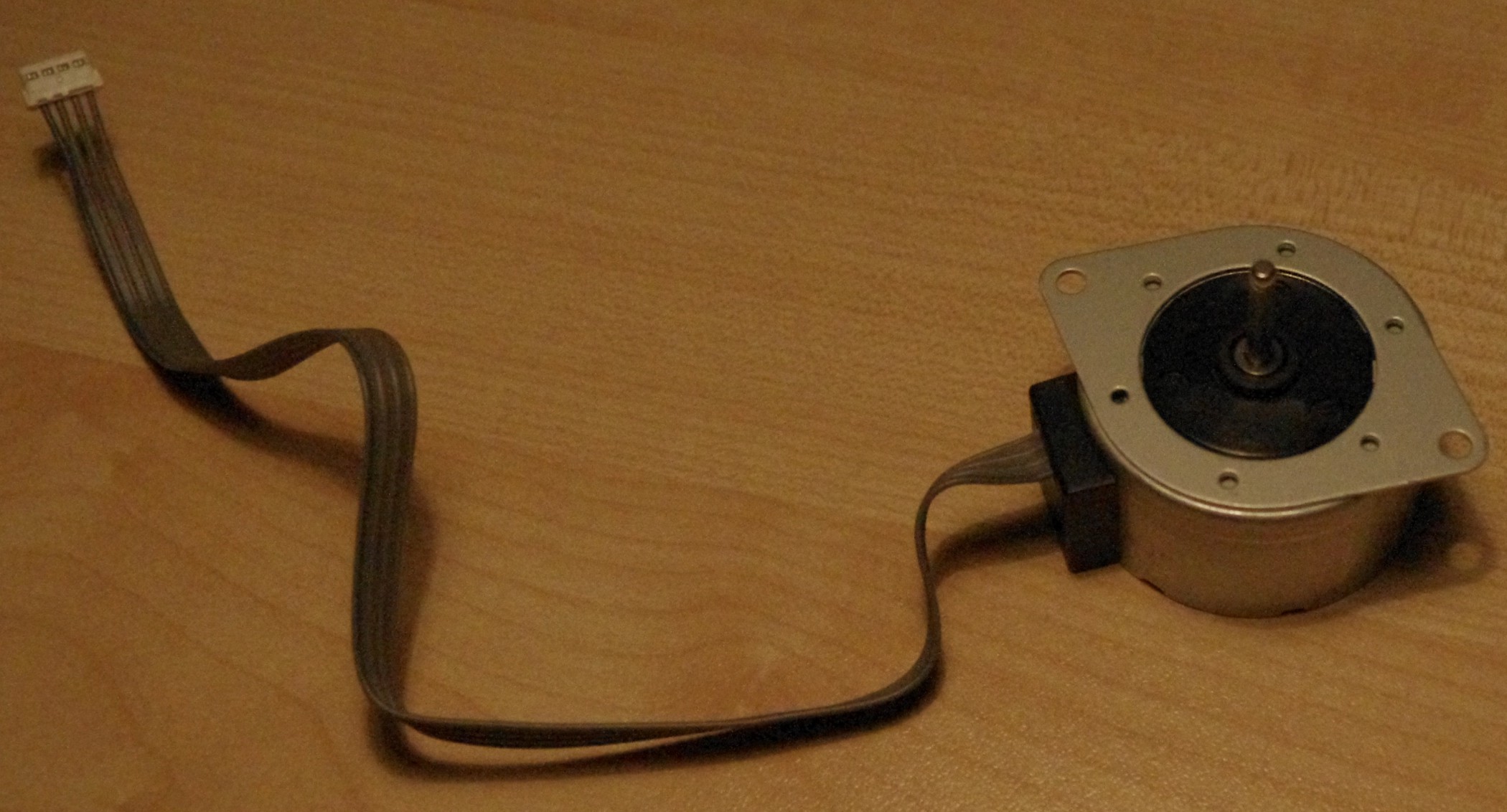
The shaft diameter on that engine is only 2.8 mm so it probably does not have any torque. Who knows perhaps I will find it some use in the final machine (focusing microscope remotely?, rising and lowering laser?, perhaps). The real engines I'm planning to use have 5 mm shaft and claim to have 0.4 N.m of torque, but they are a set of 5 from aliexpress and I want to make sure first that what I have in mind driving setup wise can work in practice as these would be quite significant part of my intended budget. So I want to be able to test them as they arrive to make sure they all are functional on arrival.
![]()
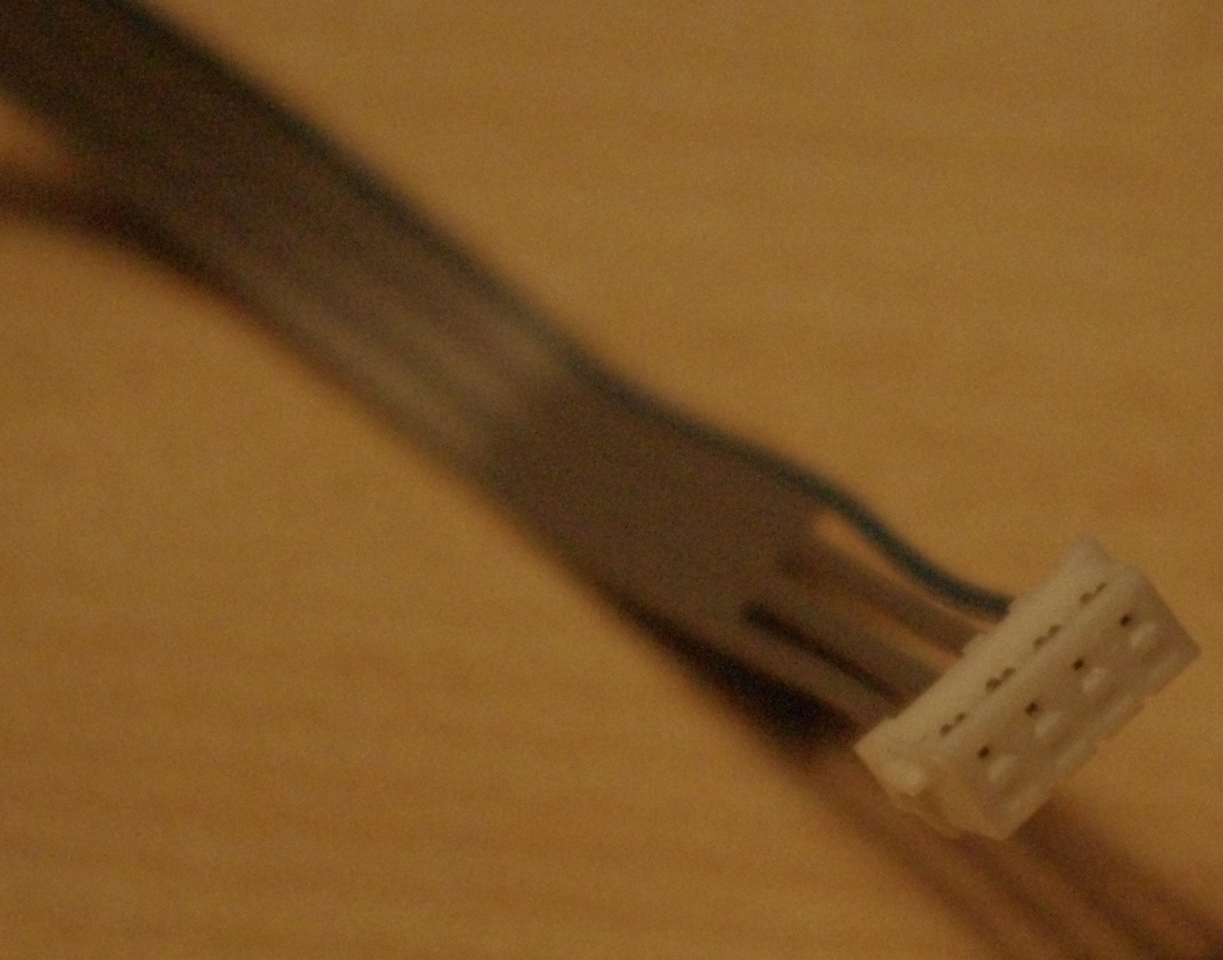
The pin sockets on that connector are much thinner than I expected. Wonder if it can really take full 500 mA. Might be. By the look of it it might be somewhere in the ballpark of AWG 26 .. or even as low as AWG 30. The wires have solid core so they do have this going for them. with the insulation the diameter seems to be approx 1 mm. We'll see I guess - I'll probably have to drag the fire extinguisher next to my table when I start testing it ;)
Hopefully, if this works, the real engines end up using will have proper wiring on them.
-
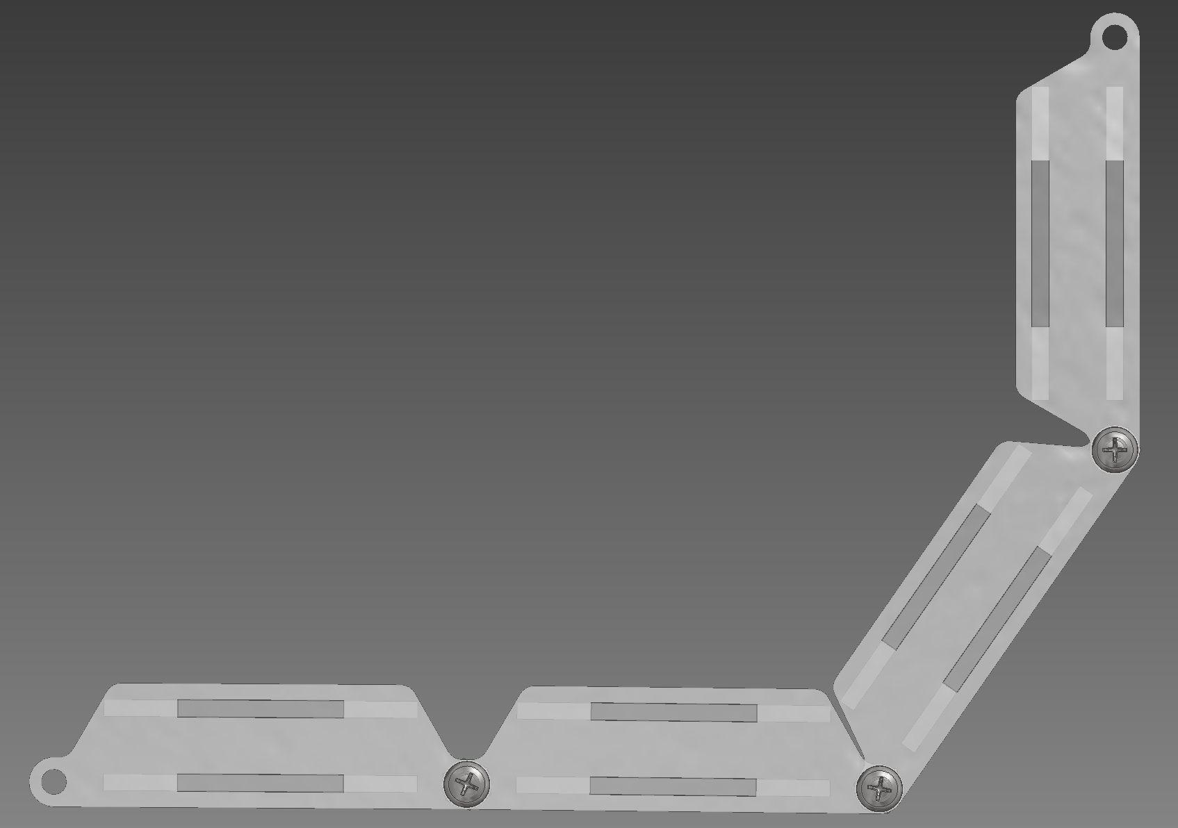
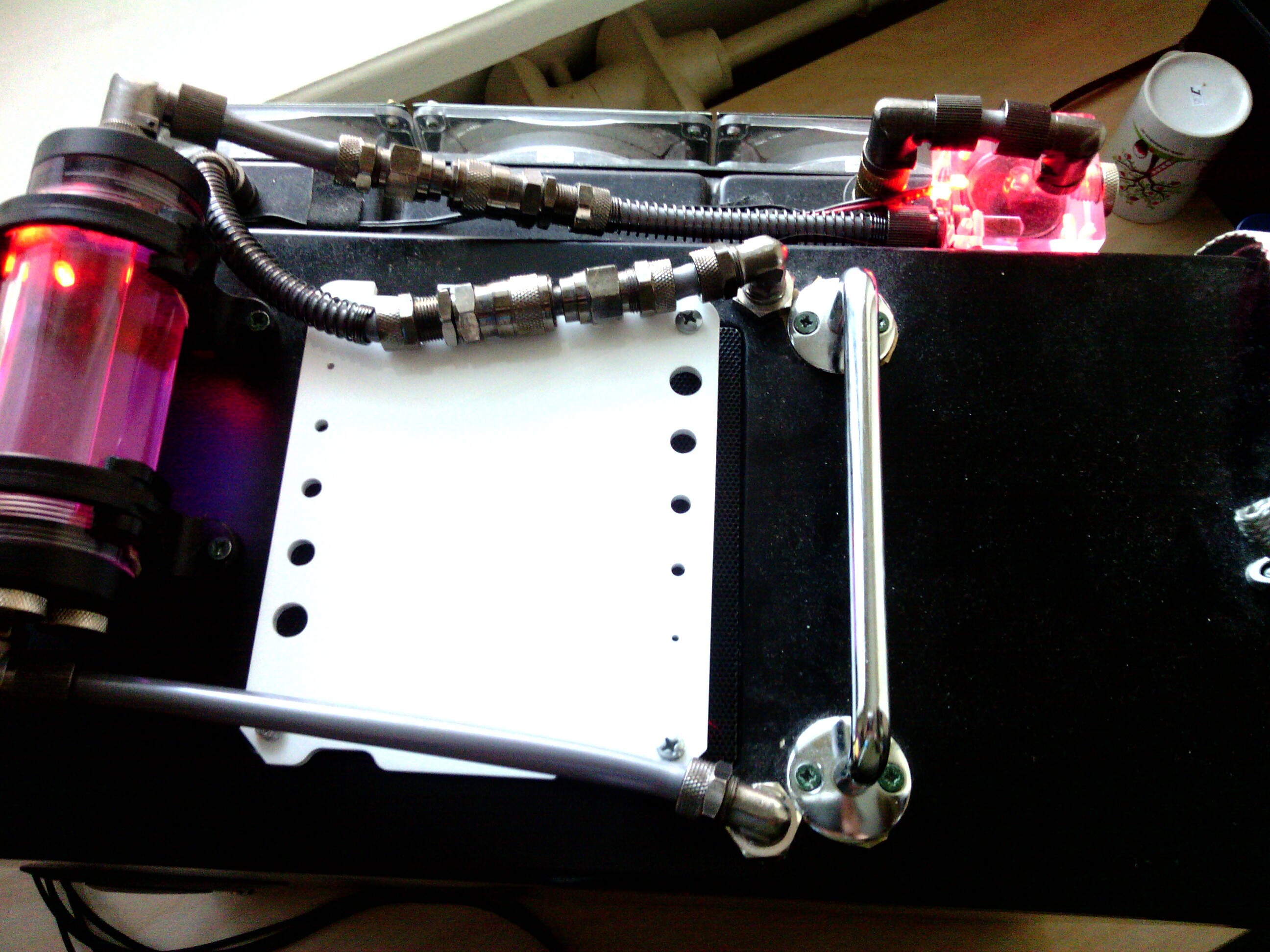
Do I need a cable chain?
02/17/2015 at 20:56 • 0 commentsI am getting to a point where I should be thinking a bit more about electronics and at the moment in particular about cable management. I am wondering if I would need a cable chain and if I need what to do about that. Obviously considering the rather tight budget buying a commercial cable chain seems not too sensible thing to do, not to mention the ones I eyeballed seemed a bit too big for my purposes.
So I am primarily considering a possibility of cutting one out from 2mm acrylic during the same cutting trip I would be doing for the rest of the laser cut acrylic parts. Edit: The relevant files uploaded to GrabCAD for this cable chain: https://grabcad.com/library/laser-cut-cable-chain-1 - note that at this point this is just an idea and has not been tested in reality.
![]()
![]()
![]()
The cable channel would be 16 x 7 mm and 180 deg turn would be approx 45 mm turn radius. For now this is just an idea. Perhaps I can get away without one, but getting one afterwards if I do need it after-all might be hassle. Alternatively I have seen some clever usage of zip ties, for example, for adding stiffness and guidance to a cabling.
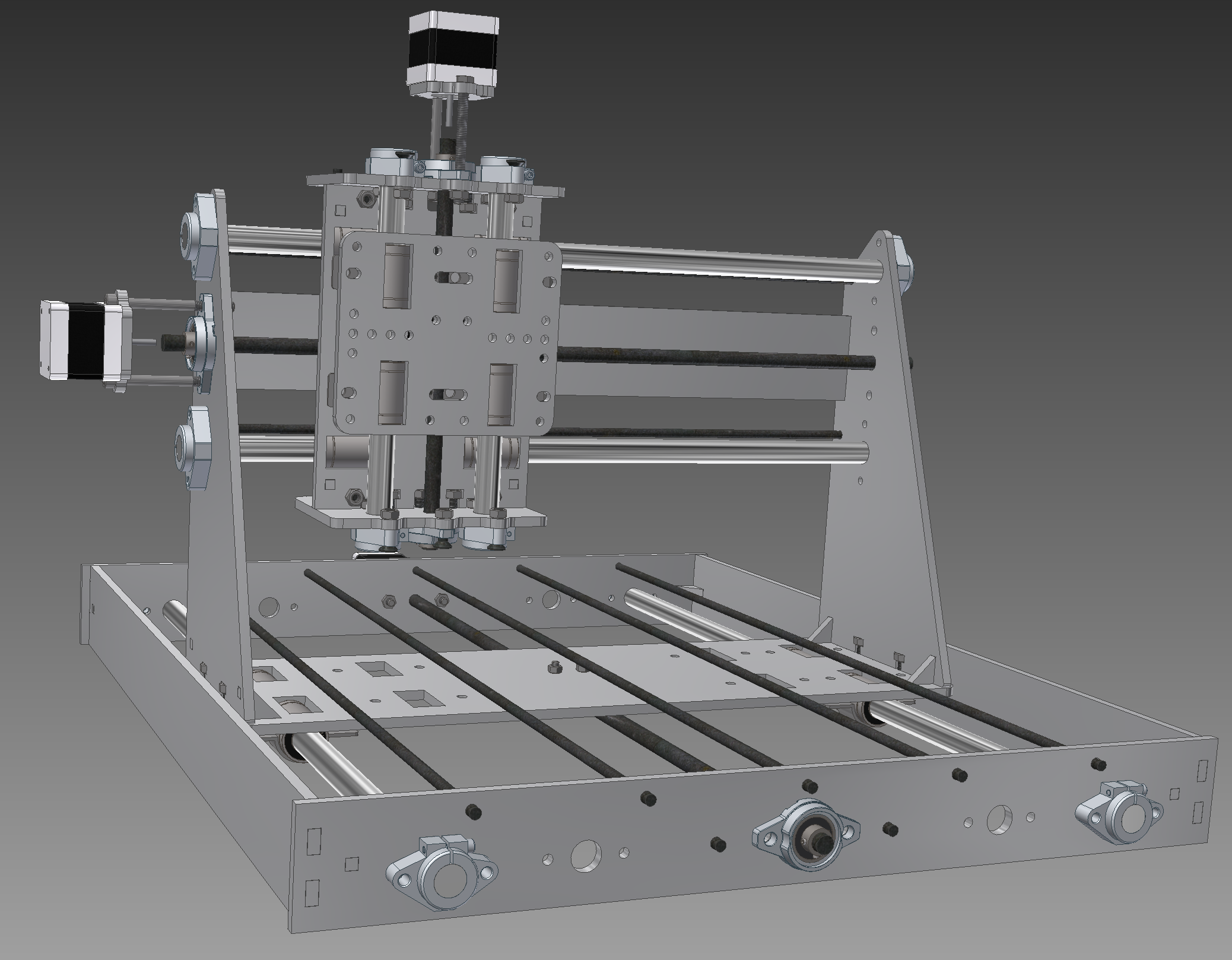
Bonus content. A front, side and top renderings of the planned machine. I have let it sit for few days on my hard disk and taken another look at things if they all still make sense. Added couple of holes here and there, rounded couple of corner where it made sense. Overall I am getting reasonably happy with it so will start figuring out how much acrylic sheets I would be exactly needing for getting it cut out.
![]()
![]()
![]()
-
Components
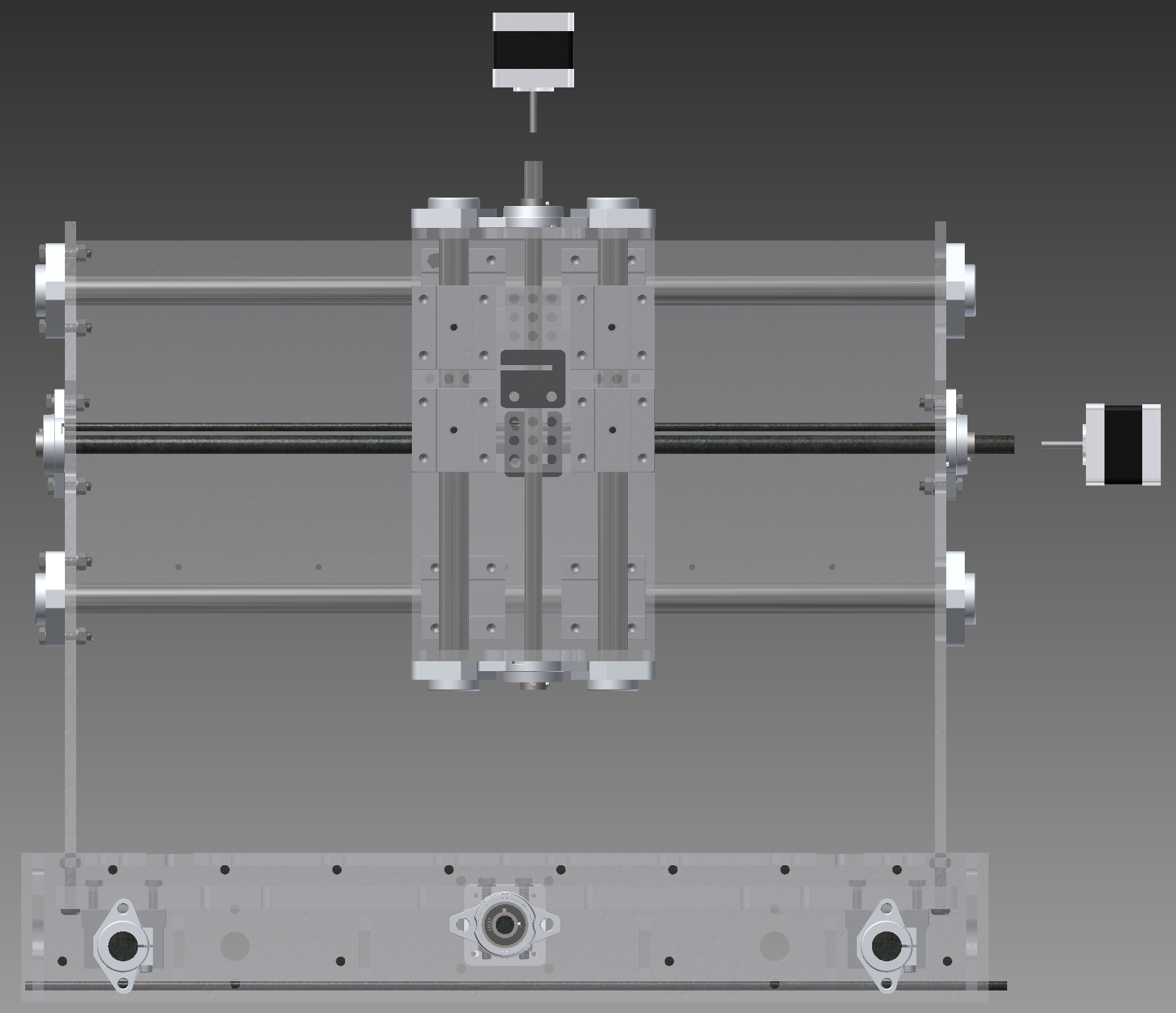
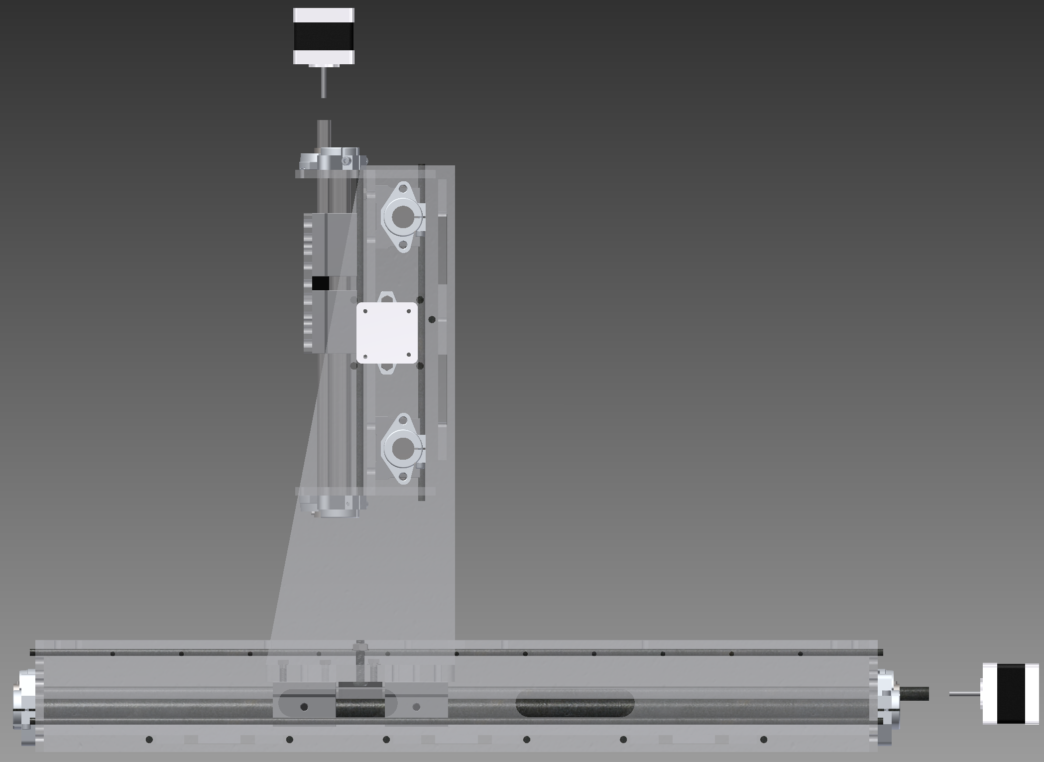
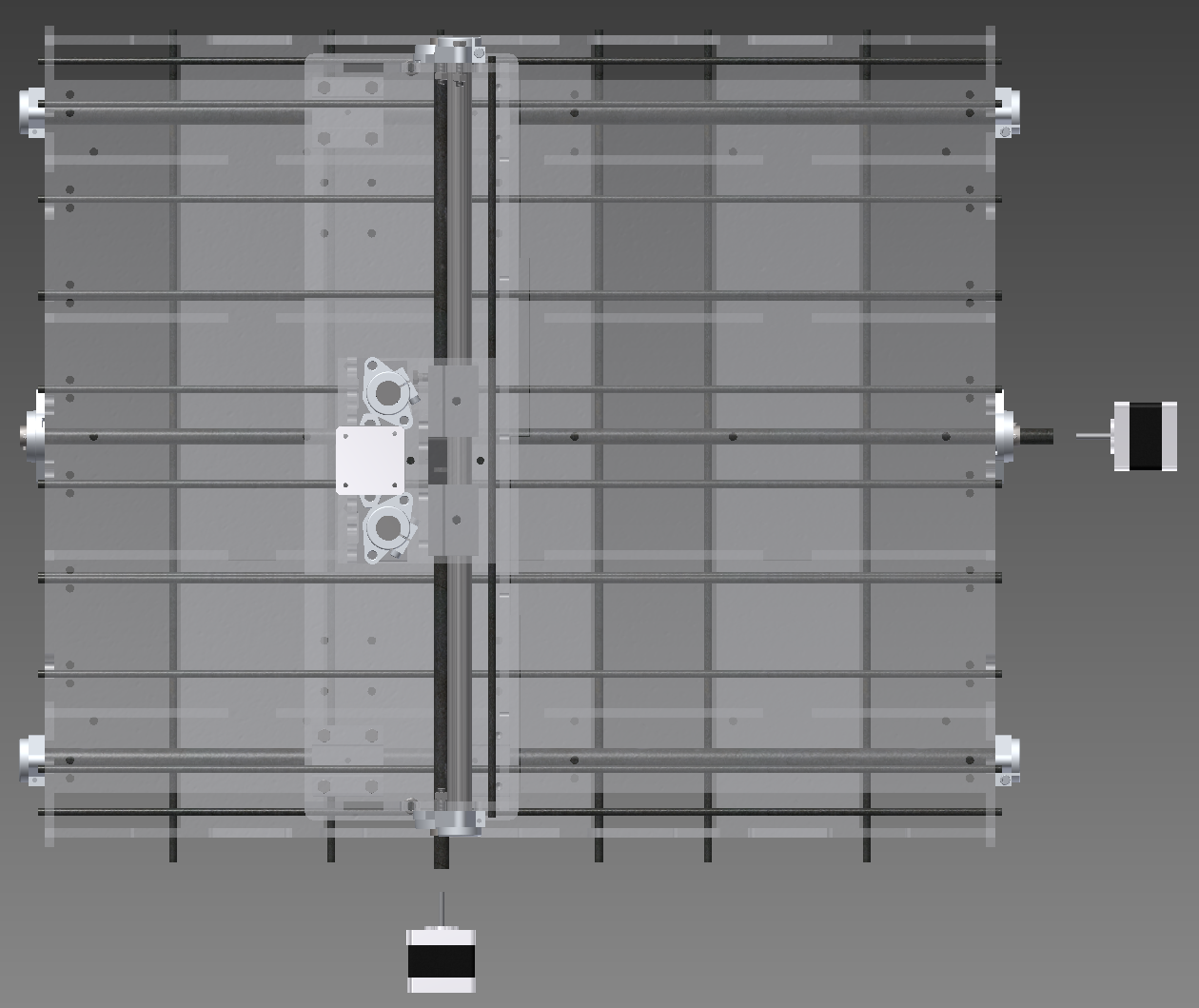
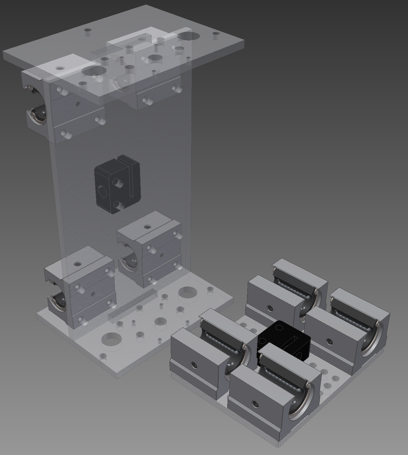
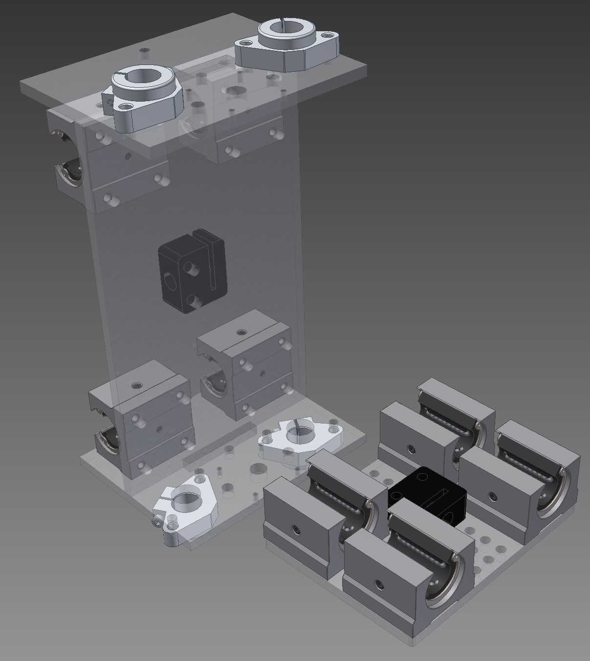
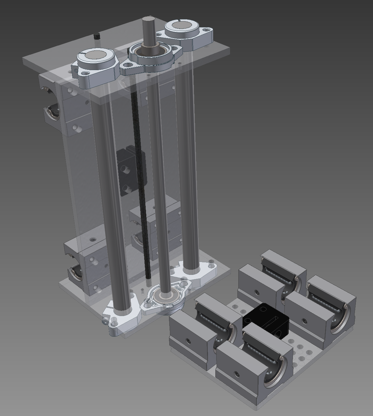
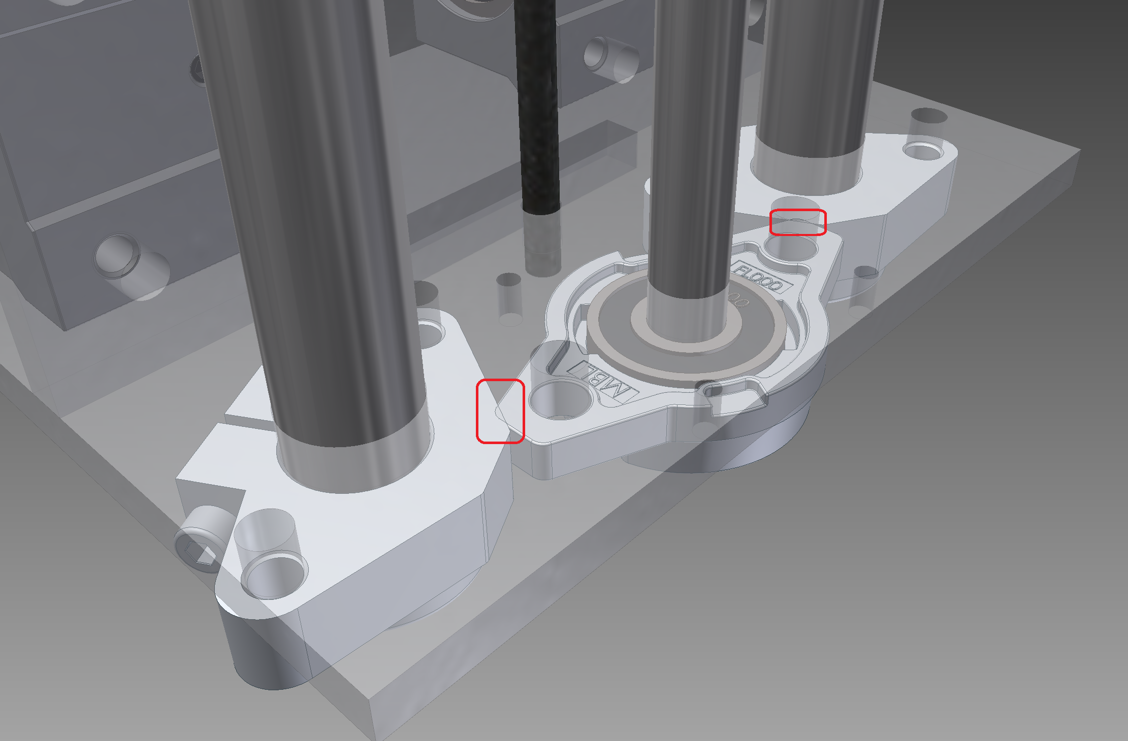
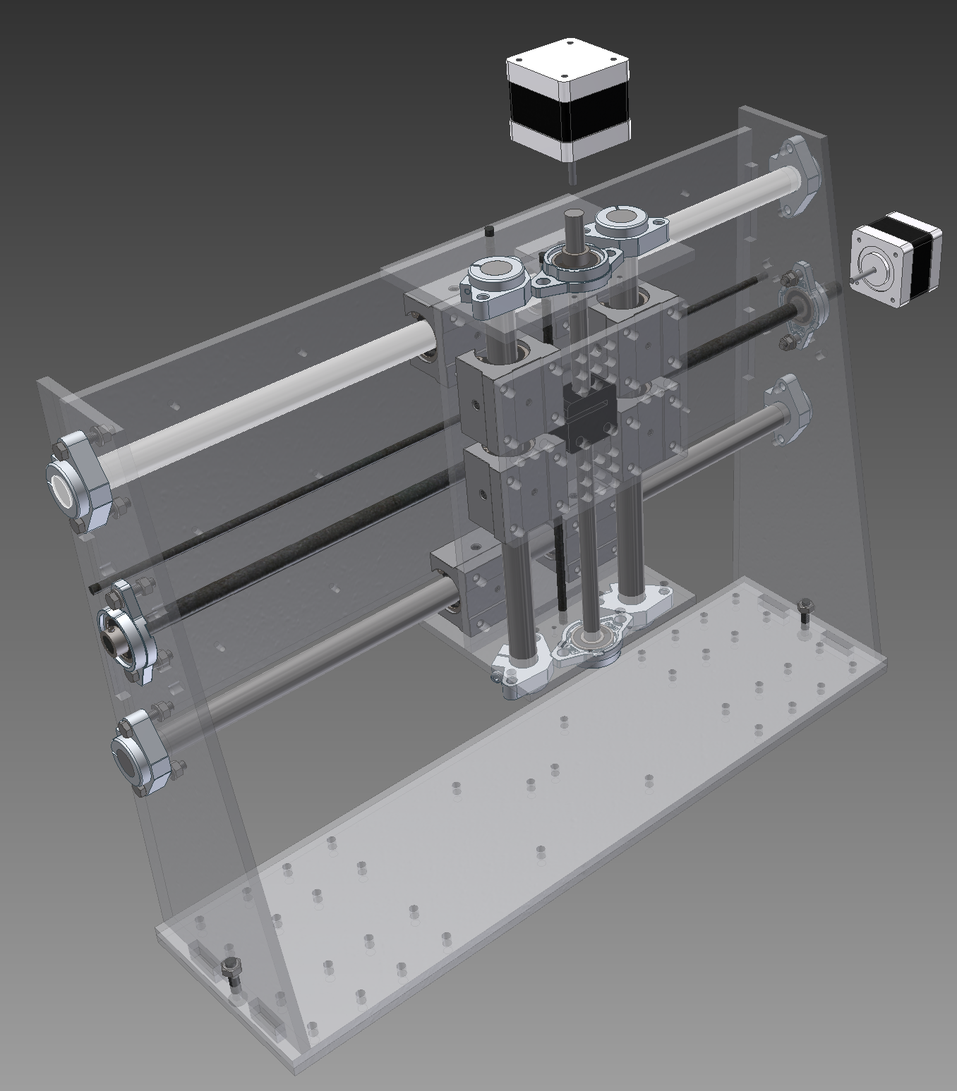
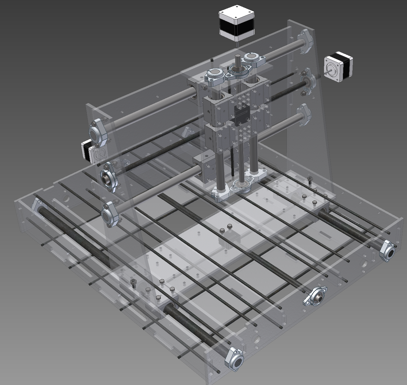
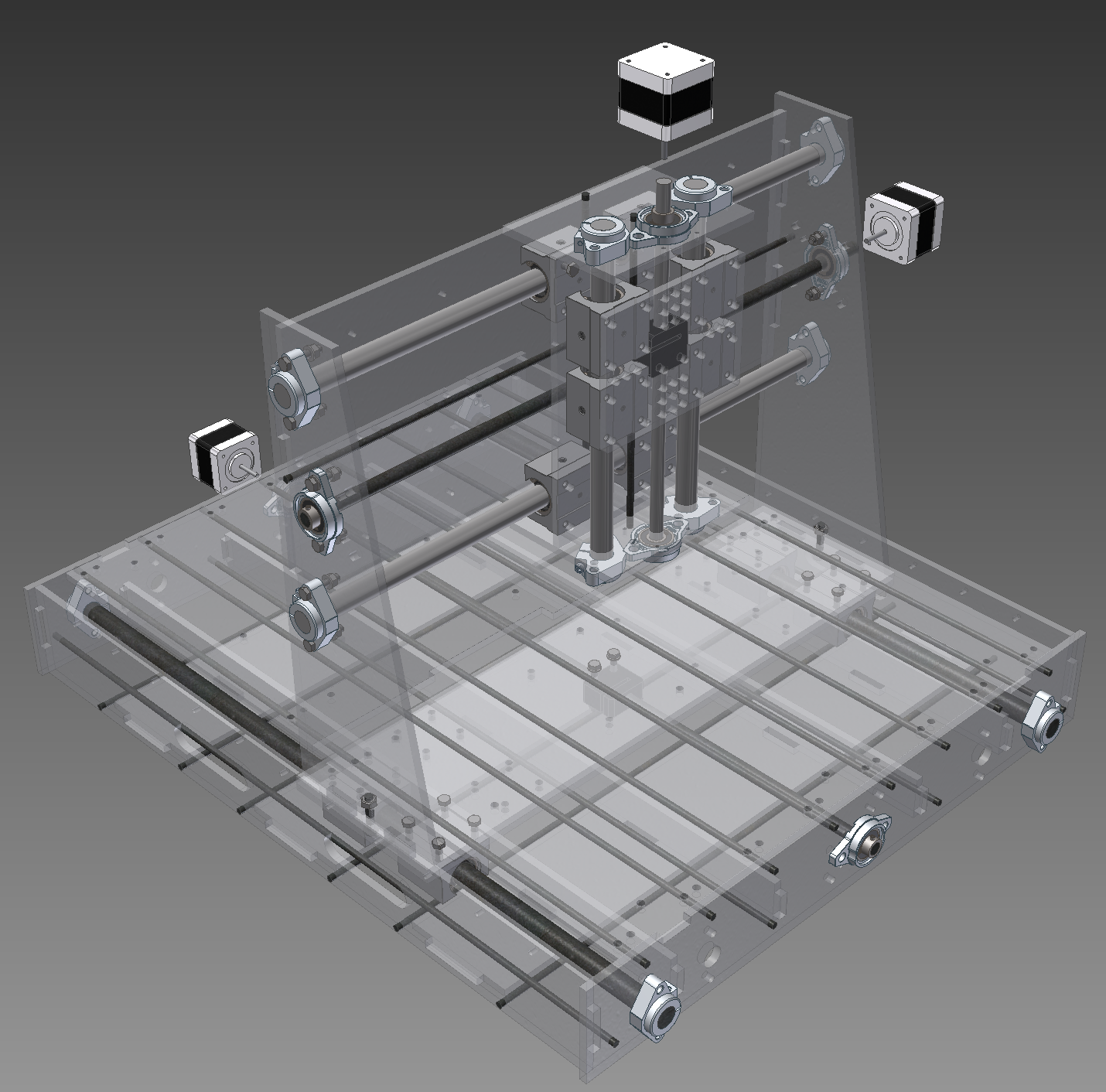
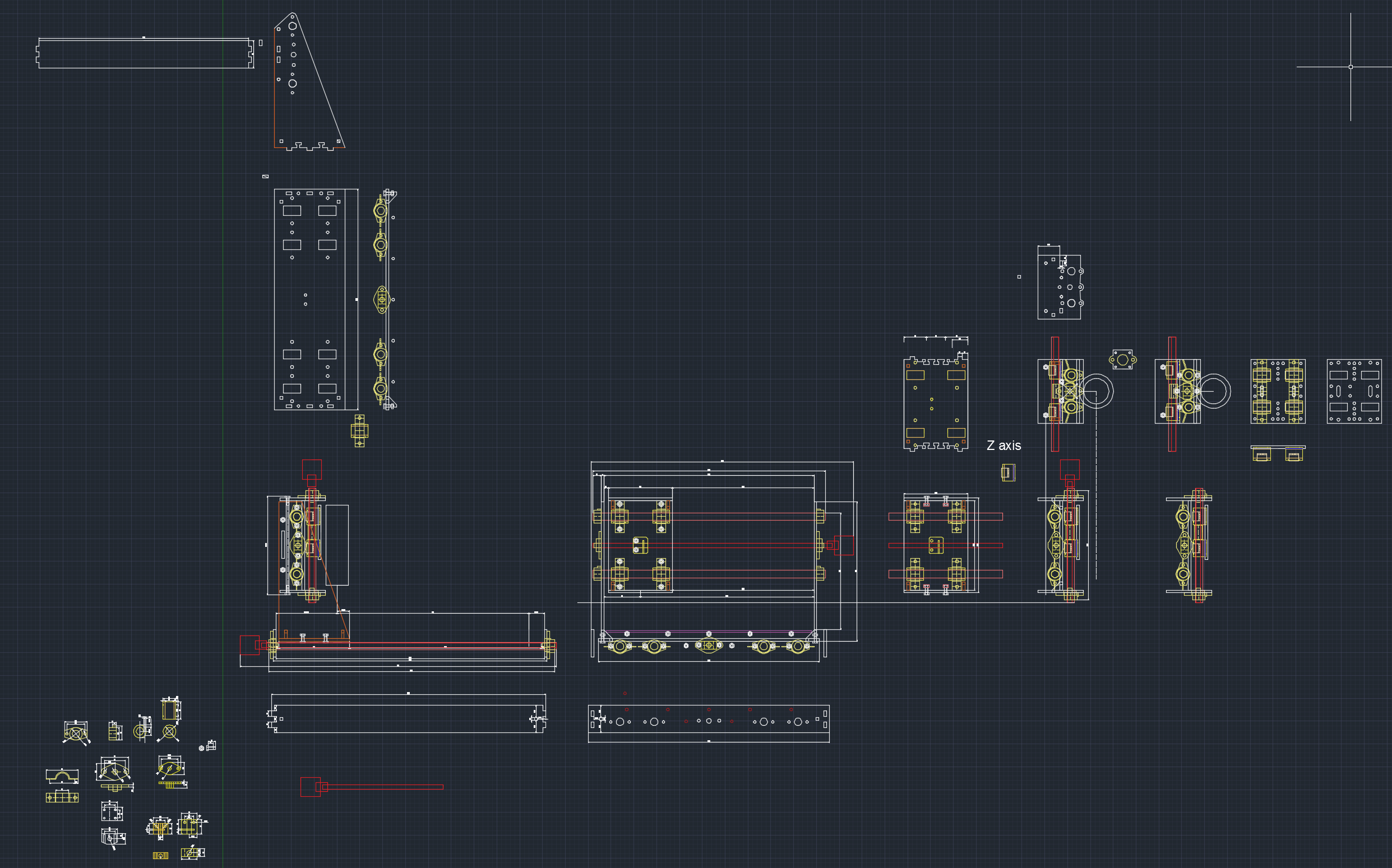
02/15/2015 at 12:09 • 0 commentsI managed to more or less finish the autodesk inventor assembly for the new revision last night. "More or less" because I did not bother adding the bolted connections everywhere where they should be. My inventor is on HDD and I suspect that which makes it to lag every time I add a new bolted connection. Rest of the PC specs I'm using for it should be decent enough to not choke on that (I7-3820 @ 4.3 GHz, 64 GB of RAM and AMD 7950 gfx card). But the point of the autodesk inventor assembly is anyway for me to see if there is any obvious problems I might have missed in the 2D design process. It does not happen often, but when you have forgot to move some opening 5 mm to the left on some component when you stretched another one 5mm in some direction it is better to find out that before I have the parts cut out and in the process of assembling it physically.
This time I used acrylic as the material for the sheet metal parts and one if the side effects of that is that the components are semi-transparent. I found out that this is actually a pretty nice for checking if any of the rods intersect or any of the linear bearings hit something they should not. Although I must add that doing the assembly is a bit more annoying with transparent components as it can be hard at time tell at a glance where are the borderlines even with borderlines highlight turned on.
What follows is a number of snapshots taken during the digital assembly process - in there it will be easier to understand what are the components and how are they arranged than a snapshots of the finished assembly rendering.
![]()
Fig. 1 - z-axis plate (right, horisontal) and the y-axis plate with linear bearings and delrin lead-nut (left, vertical). The horisontal plates on top and bottom of the y-axis are for holding the z-axis. I will probably glue them to the vertical plate although there will be also two 5mm threaded rods pulling the z-axis top and bottom plates together so glue might not be needed.
![]()
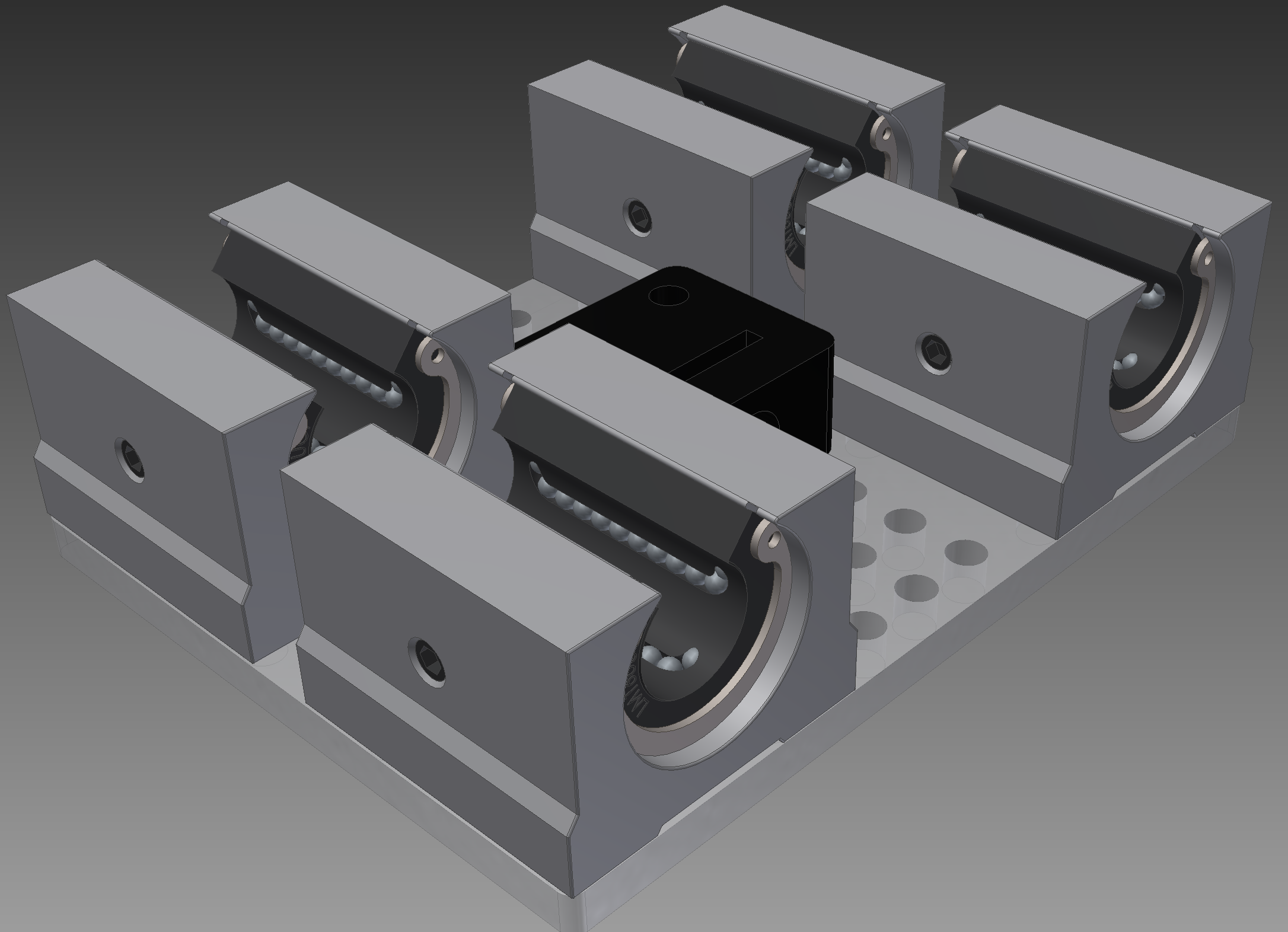
Fig. 2 - SHF16 blocks added for holding the 16mm calibrated rods in place.
It must be noted that some components I have grabbed from GrabCAD have issues - and I am not sure if I have misunderstood something myself or are some dimensions of these components wrong. For AutoCAD design process I did rough drafts of these components based on their dimensions in the spec sheets. However, NEMA17 engine and 10mm bearings have slightly different distance between mounting holes than specification for these components calls for. Same issue with the linear bearing blocks. Why is this issue - because when I am doing assembly and try to put constraints on these using the mounting holes central axis alignment for that I get an error message and must constrain them in some other way and this is annoying. It is possible that the guys who did these based their drawings on the actual physical components in their hands or it is also possible that I have missed something, somewhere. Regardless, when I look into my mounting hole I can see though the holes so reality will probably not care if the central axis of the mounting holes is displaced by 0.2 mm between components. I think ....
![]()
Fig. 3a - z-axis linear rods and leadscrew installed. Note the bottom section of y-axis plate, there seems to be a problem with SHF16 and the 10mm bearing block intersecting slightly.
![]()
Fig. 3b - zoom in on the problem area. However, as I am not confident the dimensions of the downloaded components are entirely correct I will just ignore it for now as according to official spec sheet these component with max allowed dimensions within presented tolerances just barely should not intersect. If they do, in reality, then I will just have to grind a corner off from the 10mm bearing block to make it fit.
![]()
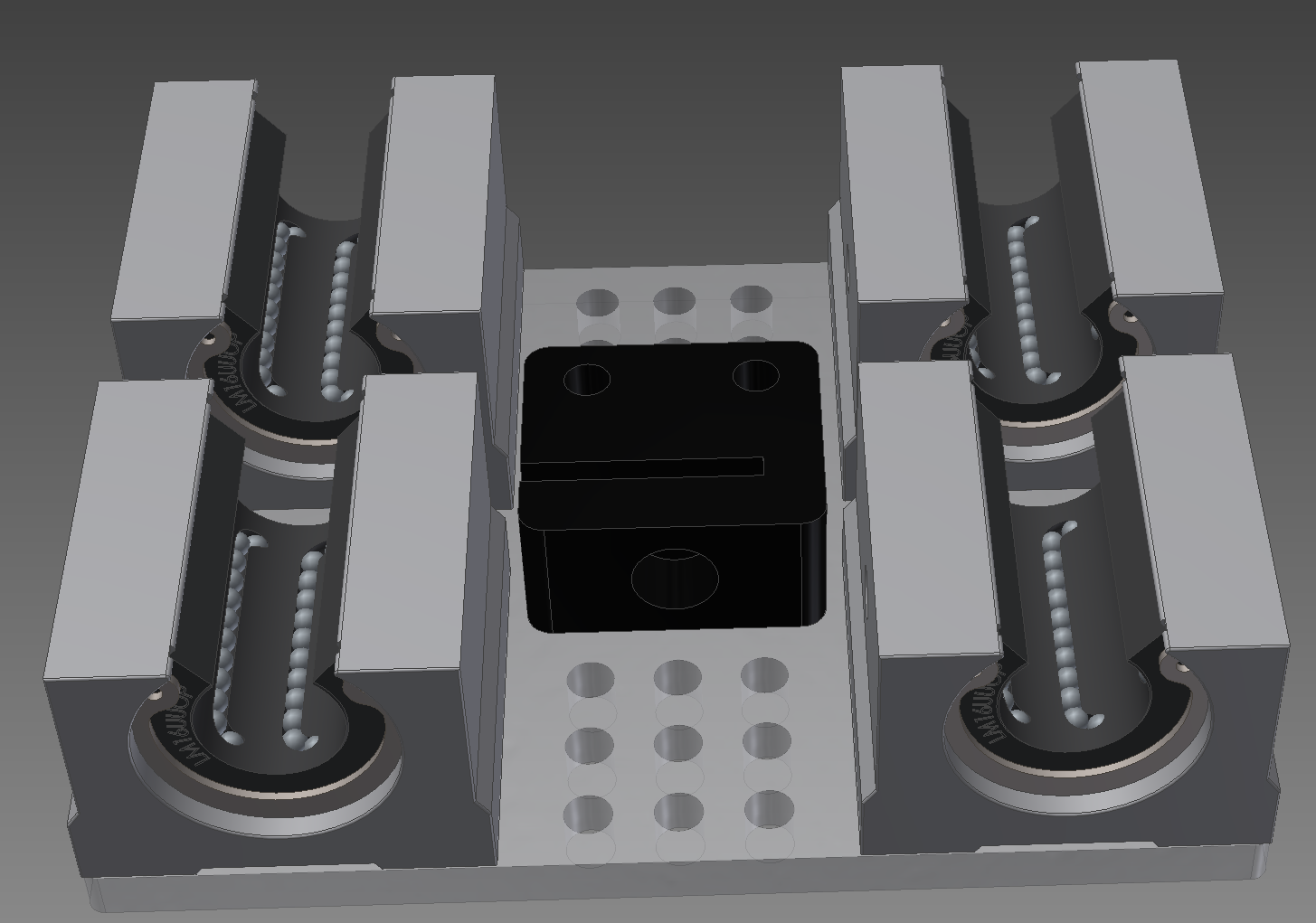
Fig. 4 - y-axis with z-axis attached to it. This is the stuff that shall be traveling along the x-axis. Note that as I decided to do the first version in acrylic and lost the little right angle corner pieces in this revision because of space constraints there is two 6mm plates in the bottom instead of the usual single plate. This is also only location in the machine where I used the "little tabs and bolthole" connection in the new revision because of the space constraints. I will most likely glue the bottom plates together although it might be also fine without glue because of relatively large number of bolts going though these two bottom plates.
![]()
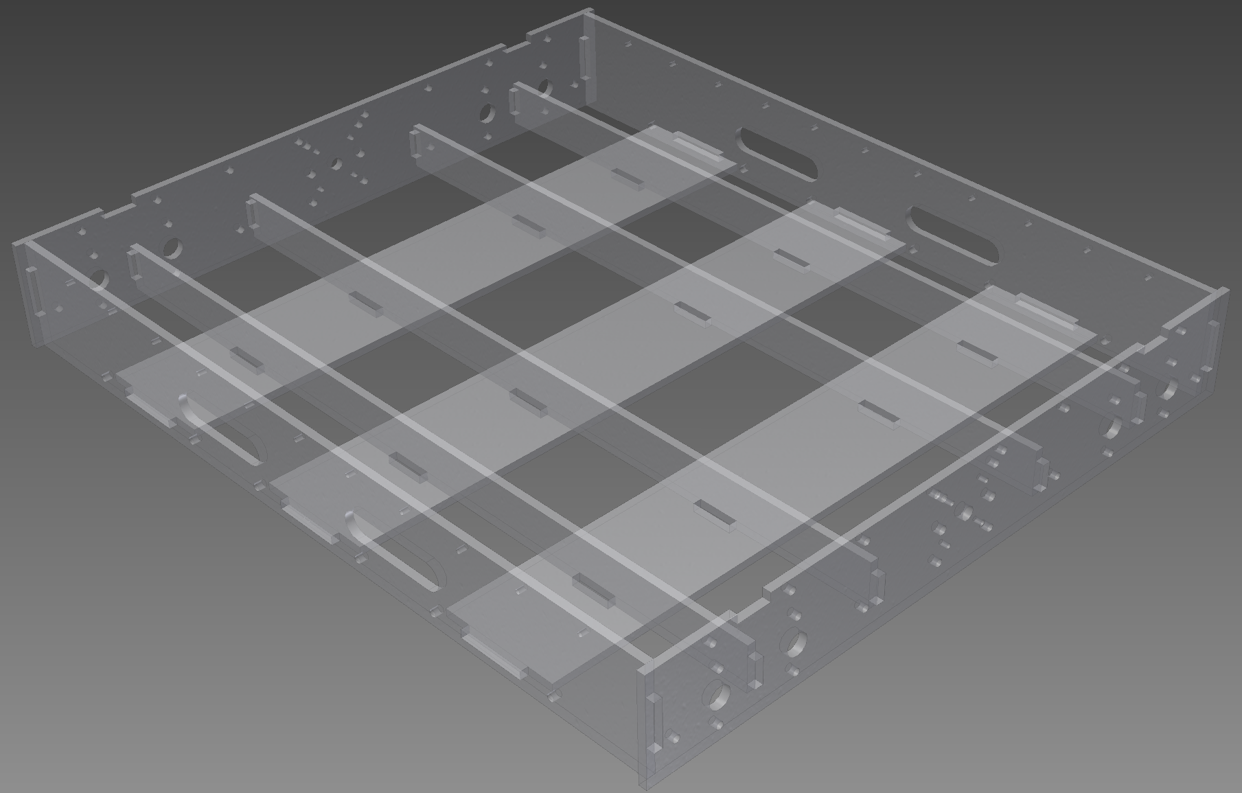
Fig. 5 - Stuff to make base frame rigid. The underlying frame I plan to glue though quite thoroughly although there will be also a lot of threaded rod to stiffen it all up. This is the stuff going into there before putting constraints on them as that way it is easier to see at a glance what will be going into there.
![]()
Fig. 6 - Base frame assembled view.
![]()
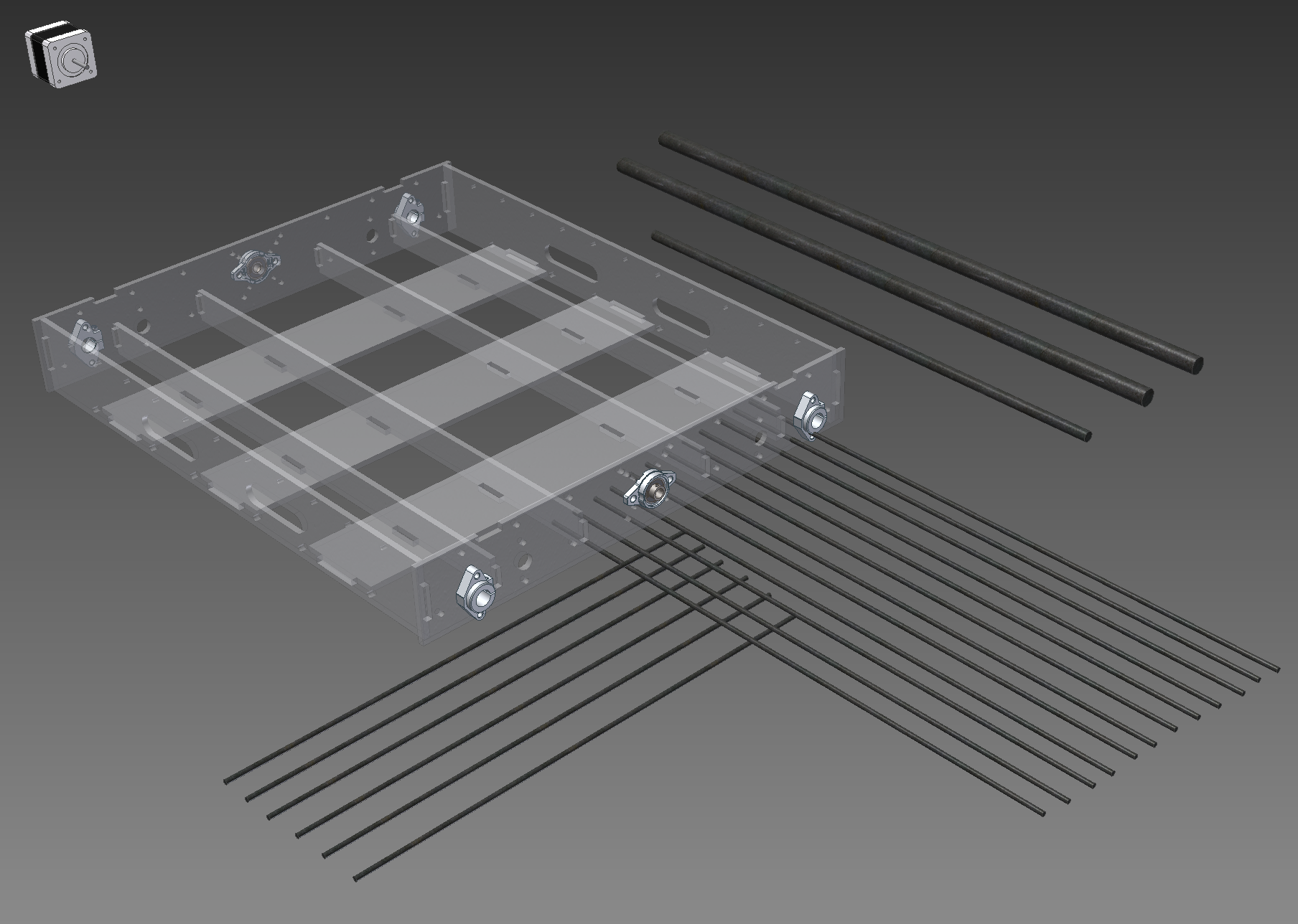
Fig. 7 - All the threaded rods going into x-axis and base frame. 2x 16mm linear rods (up to 4 of these can be used) 632 mm, 12x 5mm rod with length of ~615 mm (608 mm minimum) and a 10mm lead-screw about 650 mm long. In addition perpendicular tot he x-axis there is 6x 5mm threaded rods with the length of ~530mm (526 mm minimum).
![]()
Fig 8. Almost full machine. It just lacks the ground plate for a work-piece (which will be covered by a sacrificial board)
![]()
Fig. 9 - Ground plate added Apparently the ground plate is a bit larger than the work area of the laser cutter to which I have access to (plate is 600x450 mm but the laser is 600x400 mm) so I had to cut it in half. Left a 0.2 mm between the plates so for all practical purposes it should be pretty tight fit. The plates would be fixed to the threaded rods under them by zip ties according to the current plan.
Both side-plates have a row of little holes along the top edge which are intended for "something" that would deal with electrical wiring when the working part runs back and forth along the x-axis. I will think about it some more though. Probably some kind of cable channel, perhaps just a "U" profile attached there by small rivets.
A note about work area. It will be slightly more than A3 it seems currently. A3 is 420x297 mm and this one can have a work area of about 430x320 mm with approx 10 mm safety margins before hitting the physical constraints of the machine. However, the actual dimensions of the piece this thing would work on could be in the x-axis direction as long as you can support to be level and in the y-axis the constraint would be the width that can go in there so approx 450 mm although out of which you can probably access only about 320 mm in the middle width wise. This should be even feasible in practice with the usb microscope in the machine for setting the coordinate zero point on the X-Y plane with very high accuracy if I would, for some reason, be working with a piece which is longer. Not that I plan it to be of regular occurrence as it is probably still involve significant manual processing for making the G-code capable of handling something like that.
-
Revision 2 CAD part done
02/14/2015 at 15:41 • 0 commentsI was able to dedicate bulk of today for doing the autocad part of the new revision of the machine.
![]()
In parts it should be substantially more rigid than the first version in parts, though .. I'm not so sure. Managed to get it a bit tighter but it has cost me little right angle corner pieces I was using in the previous version for ensuring that all the angles are 90 degrees and for additional rigidness. Granted, all that is based on "gut feeling" as I have not bothered to do any calculations yet about .. well .. anything other than budget.
But this time I had an advantage of knowing that I want to build it first of acrylic. I tried to avoid the usual "hole and little tabs for bolted connection" I have seen used by other people for wooden machines and instead have decided to glue some of the stuff together. Obviously there are still little fingers going into square holes. In addition there is quite a lot threaded rod for pulling various pieces togehter ... I went with M5 for this version (previous one was using smaller amount of M6) - mainly because of weight considerations. M5 is 150g / meter while M6 was 250 g / m. There will be approx 15 meters of threaded rod in there in various places.
For X and Y it is possible to use max two steppers per axsis (one in both end) - initially plan is to use single Nema 17 per axis but I have added the mounting pattern also for Nema 23 should the Nema 17 be not sufficient (I expect it to be enough, considering the relatively modest dimensions of the machine). For Z-axis only a single Nema 17 is possible, which must be enough, considering the relatively short max travel distance and presumably rather modest loads on that axis.
There is an option to use four linear rods under the x-axis if using two is not rigid enough. By my napkin corner estimate the 16mm linear rod should have approx 0.2 mm bend through when the carriage is somewhere in the middle of it with two rods. I suspect in reality the first version will have more than that and I should not be worrying about the linear rods more about rigidity of the rest of the machine. I'll see about that, I guess, once the first version is functional. For a start I am going to order only enough parts for two linear rods under the X axis.
Should it be possible it might be easier / more economical to compensate for that kind of stuff in software instead of going for absolutely rigid structure. I have a rough idea in my mind about suitable coordinate transform for taking into account the bend through for z-axis as a function of location of x-axis (could be also easily extended to take into account bend through in both X and Y direction if needed). It is relatively simple (in my mind so far) so hopefully someone has already done something like that. Of-course in reality things that should be simple, in principle, can have some technical challenges associated with them ;) Presumably I will have plenty of time to play around with linuxcnc before my machine is properly functional so I'll think about it more when I reach that part.
The idea is just mapping the bend through with a dial either in 1D or as a 2D matrix, then fitting the results with a suitable function (at first probably just a second order polynomial either in 1D or 2D) and then just applying a correction term to the z-coordinate in G-code to take into account the bend through in that particular x or x/y value.
Almost none of the DIY CNC projects that are shown in the net talk about calibration of the machine. I assume that to be actually quite important part of the machine construction if aiming for any kind of reasonable accuracy.
-
New linear bearings - new iteration
02/13/2015 at 20:37 • 0 commentsThis is a short post about how, roughly, the thinking process goes for figuring things out for this machine.
I prefer to go from top to down - I guess its a habit I picked up probably when I worked in engineering bureau during my masters studies doing autocad drawings for housing construction. All the forces must hit the ground eventually in housing construction after all ... And CNC bench is abstractly speaking just a small construction with moving parts.
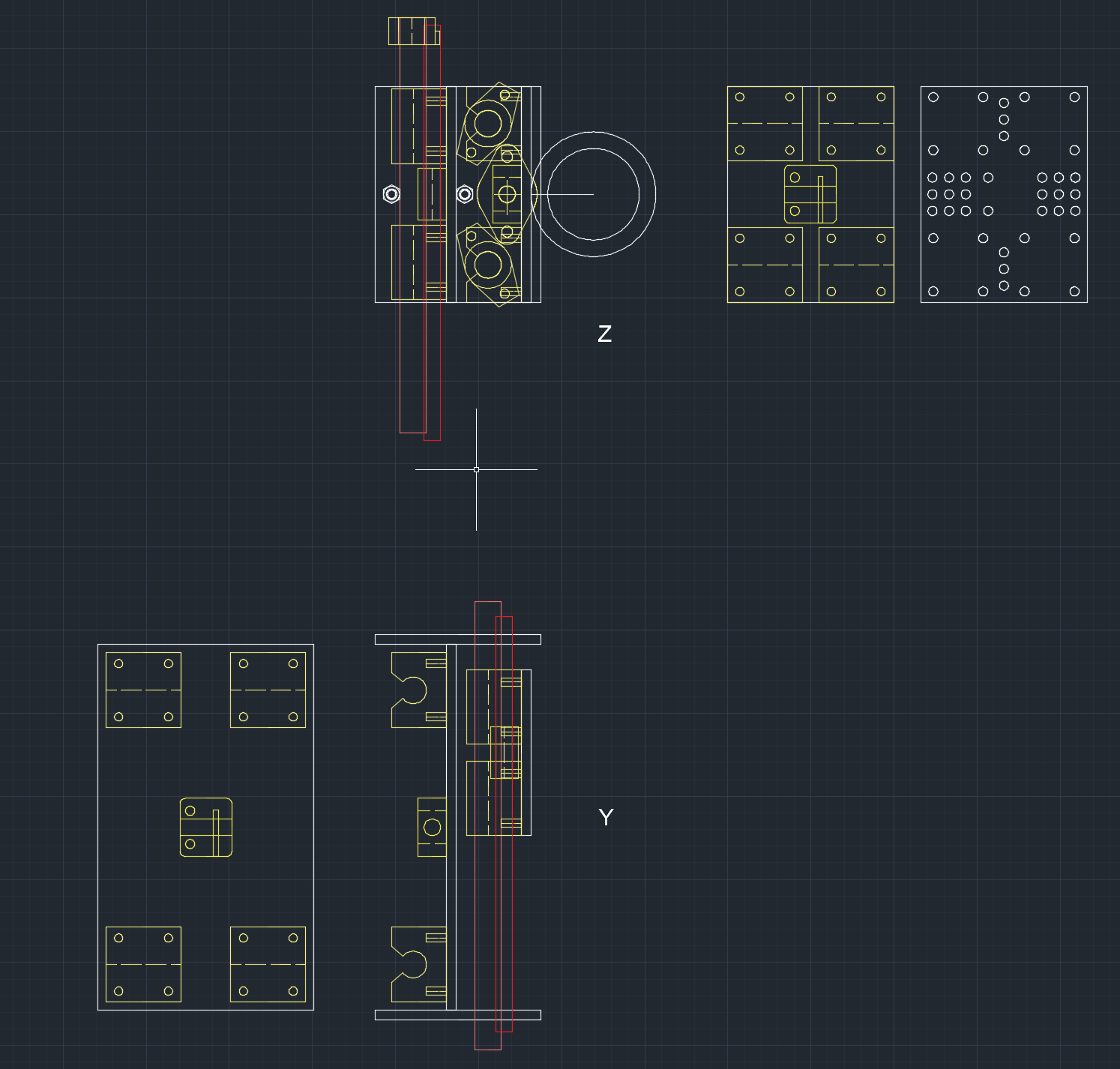
So this means I'm starting from z-axis. First just roughly drafting up how small can I make the plate which should end up holding all the useful stuff with the lead-screw and linear bearings attached to it. Then how that z-axis plate would be related to y axis, then how y axis is associated with x and then it's basically all figured out. It is kind of iterative process with a lot of moving around blocks and stretching and rotating for getting the geometry more or less figured out. After all that is done then will be the part where I will make it as rigid as I can within the constraints of remaining space....
![]()
This is the current draft with the progress I did this evening after I got the daughter to bed. And this is how the z-axis plate would look in autodesk inventor. With the linear bearing blocks and the lead-screw nut attached to it. Pretty crowded but should be functinal enough.
![]()
![]()
Once I get this version of the machine properly figured out I'll do some rough math about deflections and so on but probably the final test will be the reality once I get it all done.
Current dimensions of the z-axis plate are 130 mm wide and 100 mm high. It will have 120 mm of potential travel space between the horizontal plates (total distance 220 mm) out of which I plan to use about 80 .. 100 mm for actual z-axis movement range.
-
Something to hold the linear bearings in place.
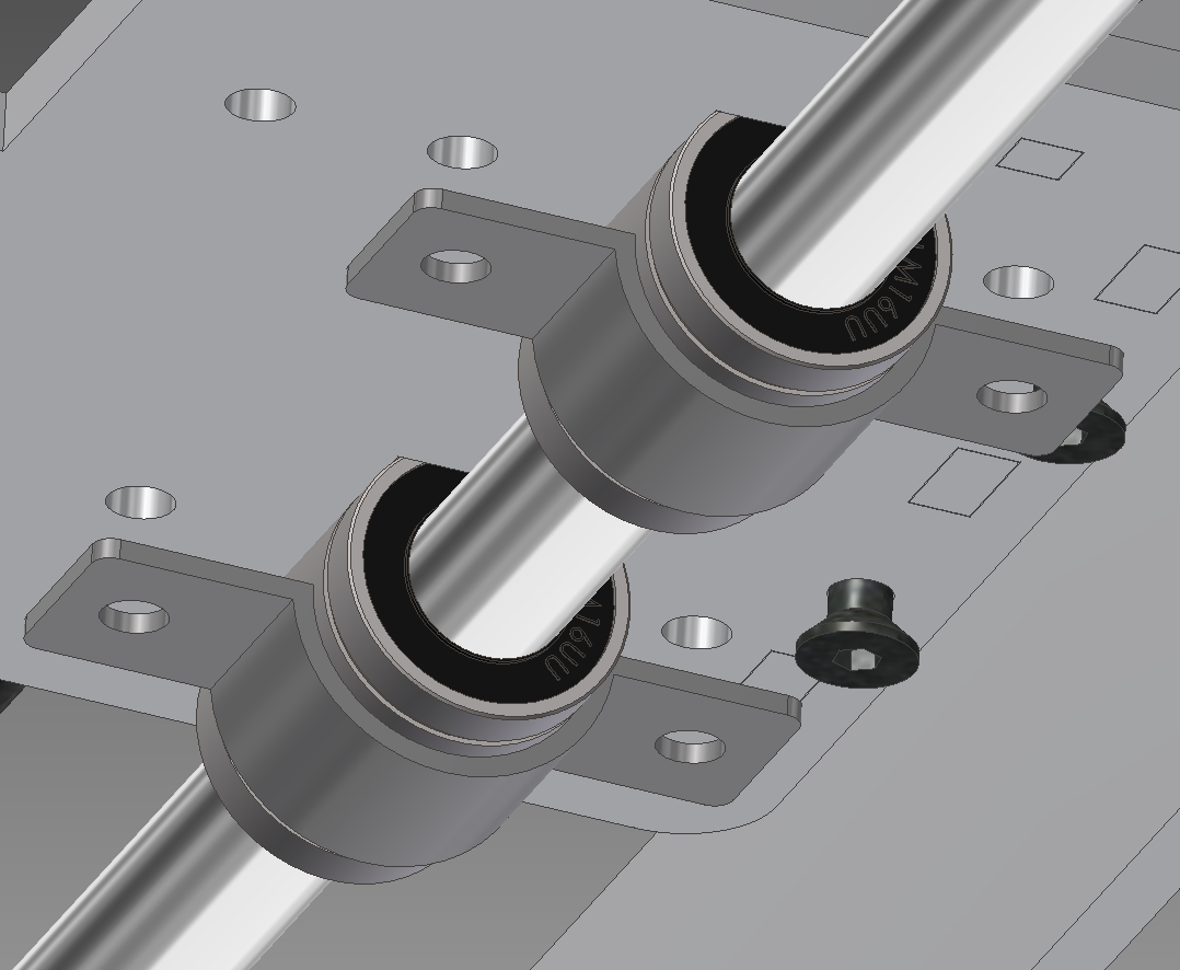
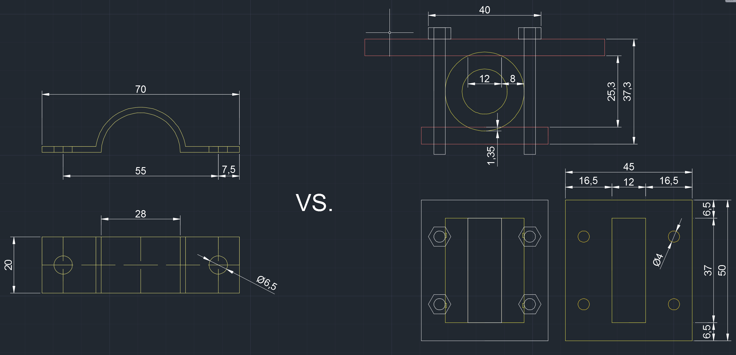
02/12/2015 at 20:37 • 0 commentsAs I mentioned currently my plan was to hold the linear bearings in place with the pipe fasteners and a 37x20 mm cutout in the board. I am not happy with that anymore, though.
![]()
It is pretty wide (70mm) for a start and uses M6 bolts. Out of these two being a bit too wide is the main issue as it costs me about 50 mm of potential work area in z and y axis. So I have a new idea to use instead smaller acrylic plates to hold the linear bearings in a smaller cutout (M4 bolts). Something like this
![]()
I have some reservations if 6mm acrylic is mechanically durable enough for that as I have not worked with acrylic before, but the price per bracket should, in theory, end up even slightly lower than using the pipe fasteners (that cost about 1 EUR a piece in the local hardware stores in the needed size). The draft is with zero tolerances - final part will need some wiggle room. Another note is that I'm not particularly happy about these cutouts either - the contact surface with the linear bearing would be rather small and needed tolerances far too tight for it to work in real life I suspect. Plus I'm trying to not over engineer stuff - at the cost of extra component - I could just add a extra bottom bracket as well.
![]()
Note how, if I use 6mm thick plate the bottom plate would touch the linear rod with zero clearance. Using some other material thickness, on the other hand, might drive up the costs a bit more and add complexity to the machine I'm not that keen on.
I will, probably, end up using the two different thickness plates approach as it seems, after some thinking over it, it seems more reliable than getting a 20x37 mm hole in the plate doing the moving with uber-tight tolerances so that all the linear bearings would be perfectly aligned. I will probably have to visit the shop I looked up which sells acrylic and see what the prices are - perhaps it is not that bad and I can get few sheets of 4mm acrylic as well without doing too bad things for the budget.
Then it would be time to do some numbers and figure out if it would be after all more economical to get the linear bearings with mounting blocks vs jury rigging something together myself.
Edit: After sleeping over it I have decided to do some more digging in ebay/aliexpress to dig up more options for linear bearings with a block. Even with the extra shipping charges associated with heavier packet it should turn out to be much more reliable than re-inventing the wheel myself. Preliminary digging around with my morning cofee indicates that a semi open 16mm block could come out about 3 EUR extra per linear bearing. Sure, that is about 10% of my intended budget but at the end of the day with everything considered doing my own mounting option in acrylic might not come out substantially cheaper and definitely would not come out much cheaper if I would have to do it in metal. Pity there is no 12mm calibrated rods available around here. Linear bearings for these would be more economical. The rod sizes available around here are 8 mm, 10 mm, 14mm, 16mm, 25 mm and upwards for the calibrated ones.
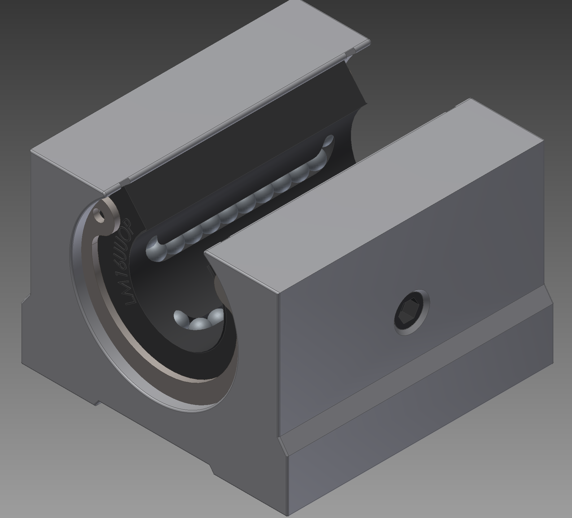
I think I will use SBR16UU linear bearings. These are the "open" kind with a cutout for a rail supported rod but that is not the reason I'm opting for these - main reason is that they are 5 mm smaller in height than closed ones (33 mm vs 38.5 mm in height) and smaller width wise (45 mm vs 50 mm). The fact that they are open ofc means that they are probably mechanically not as durable if force is applied in a "wrong way" but then again I'm not expecting particularly violent forces considering the relatively small dimensions of my intended machine. If crap starts getting in them through opening on the side I can just apply some duct tape over it to cover it up.
Opting for "real" linear bearings with mounting block was ofc not gentle to my budget. It went from approx 190 EUR up to 230 EUR before frame assembly. That leaves only about 70 EUR budget for getting the frame done and for any unforeseen obstacles. But we will see, the budget is more of a guideline than a hard limit atm (within a reason) - it is, afterall a bang for buck machine, so as long as extra expenditure yields substantial benefit it must be considered. What I spend in extra budget I win in the construction being simpler. I ... think...
As an added bonus someone had already done it and uploaded to GrabCAD https://grabcad.com/library/sbr16uu-16mm-open-linear-bearing-1
![]()
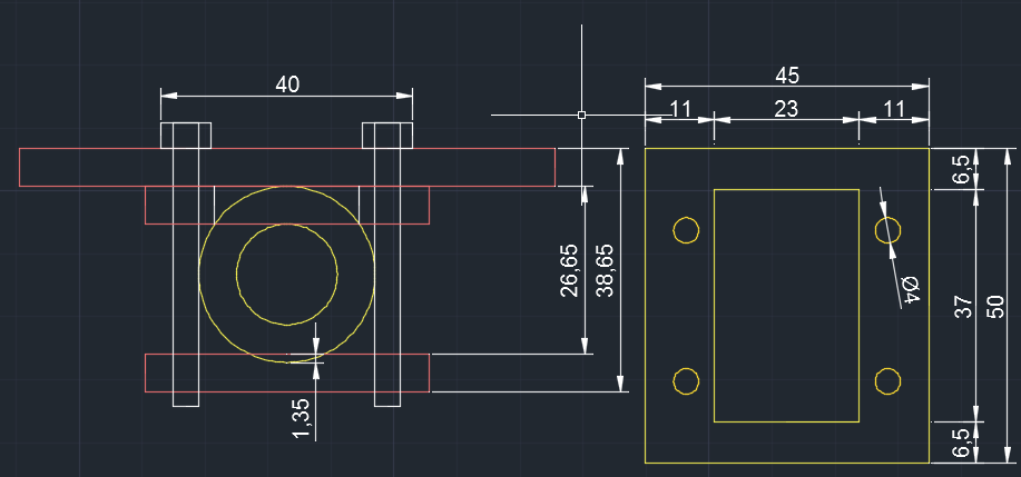
Did also a new draft in CAD based on the numbers on the spec sheet. I suspect the height of that block I grabbed from GrabCAD is off by about 4 mm or I have missed something. Anyway - in my thinking process for the new revision (Which for me happens in AutoCAD) I'm planning to use following draft
![]()
-
A Laser !!11!!
02/12/2015 at 09:59 • 0 commentsIt was pointed out to me by one of my friends (when I was complaining how hard it is to get crap laser cut) That there is a Makerlab in Tallinn with a 70W laser. The ticket for a day is about 10 EUR and access to the laser costs about 5 EUR / 30 min. Obviously 70W is not quite enough to cut aluminium (they have also a CNC router but I will investigate that one a bit later probably). It IS sufficient, however, to cut acrylic.
Now I am not really familiar with acrylic as I have never used it before. But hey it's a laser so how could I resist? So my CNC machine plan evolved into containing the "alpha" version in laser cut acrylic. On the past sunday I took the time and went to visit that Makerlab, getting a short safety instruction about where not to stick my fingers if the laser is humming and how to upload the autocad drawing and press "start" button. Well - there were also some numbers to be inserted like cut speed and beam power which were in some not very well formated txt file on the desktop of the controlling machine. I got hold of some scrap acrylic left over from previous projects waiting the trip to dumpster and did some trial and error for the cost of 15 EUR altogehter. I am not going to put that into the budget or I would be way overbudget far too soon ;)
![]()
A 180 mm fangrill made of 2mm thick scrap acrylic.
![]()
And a test piece made of 6mm thick acrylic (sitting there to prevent snow or rain going straight into my PC when I lug it around).
I also tried the same fan-grill in 6mm thick veneer but at the chosen parameters laser did not cut through that all the way.
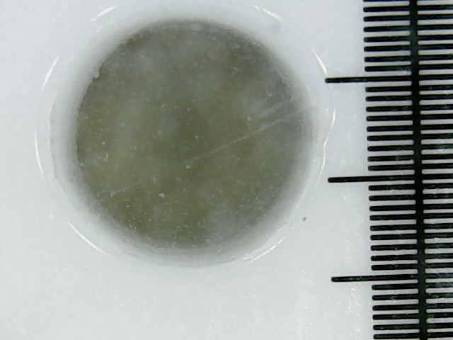
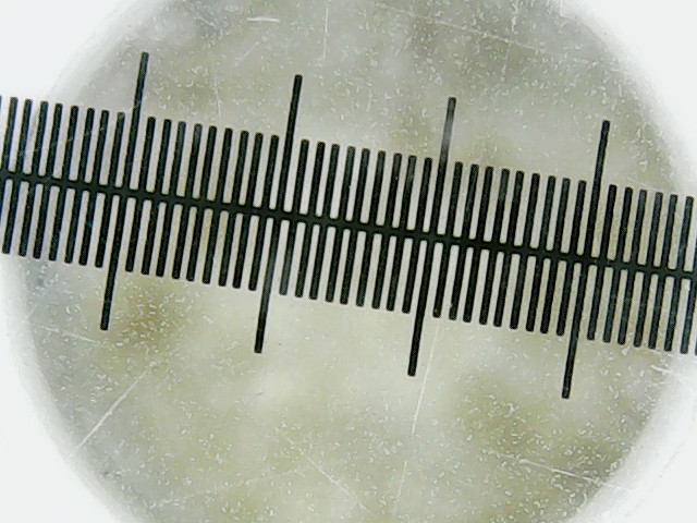
Overall color me impressed. I like that laser. Just the cut line is far wider than I expected from a laser. The guy babysitting me during my first use of the laser noted that the cut line in acrylic is "approximately 0.5 mm wide).
![]()
A 2mm and 4 mm hole ended up to be about 2.4 and 4.4 mm in diameter so seems like correct ballpark. Will have to figure out if I will need to compensate for that in the CAD drawings or there is option hidden somewhere in the laser control program to set automatic kerf compensation.![]()
Also the holes did not end as pretty as I would have liked occasionally:
![]()
Probably will need to do some more test runs before I find the parameters for the laser to go ahead and start cutting out the pieces for the CNC frame "alpha" version. But not too bad for the first run.![]()
Pictures are taken with a cheap USB microscope from china (which I am intending to use for setting zero point in the finalized machine), tick distance on the scales is 100 micrometers (0.1 mm).
I have my doubts if a 6 mm acrylic is suitable enough for a desktop cnc machine but we'll see. If nothing else it will be a nice test machine to see if everything fits togehter as intended in reality.
The work area of that laser is 400 x 600 mm so that can set some constraints on my machine if I want to get all laser cut parts done on it.
-
Every journey starts somewhere
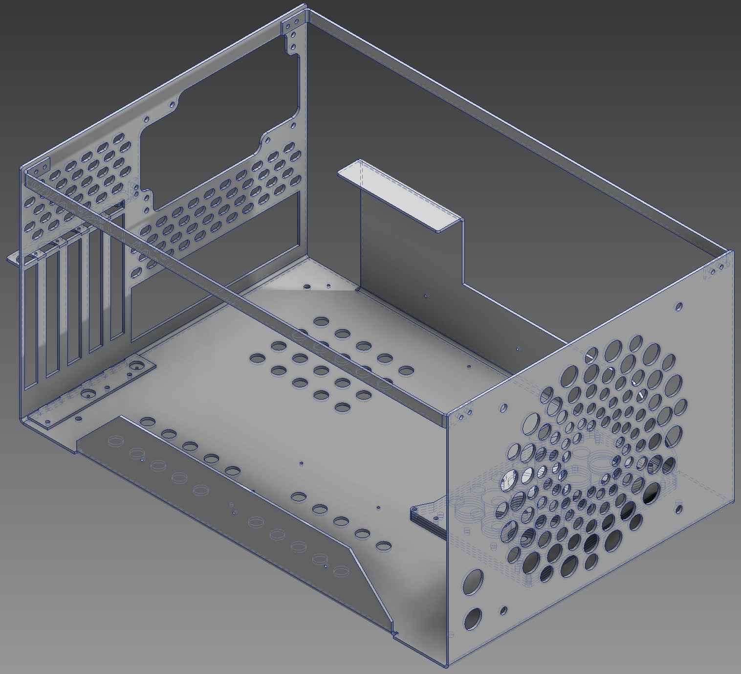
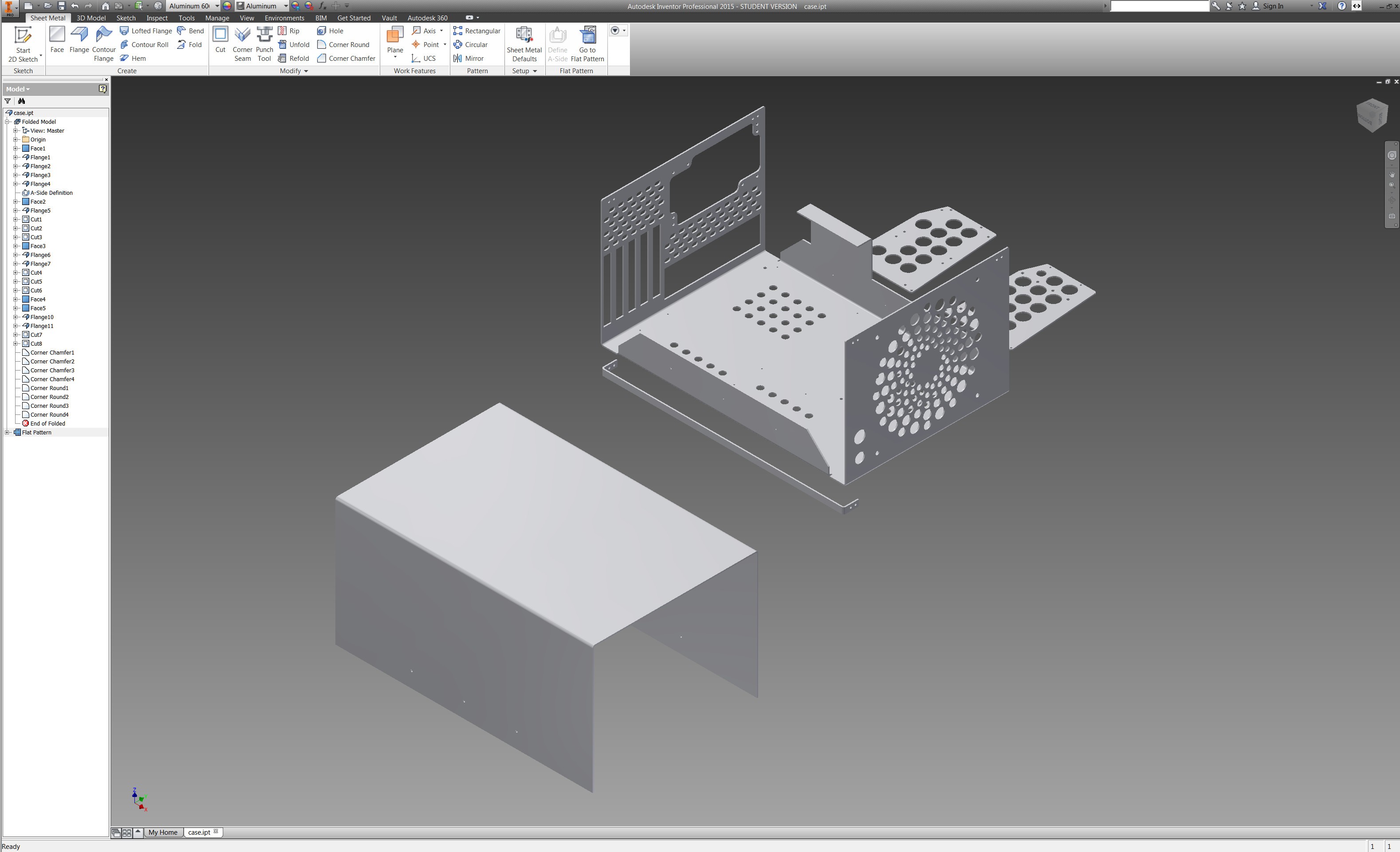
02/12/2015 at 08:49 • 0 commentsSo ... everything has some kind of start as does this project. For a start there was an idea to do a custom PC chassis out of 2 mm aluminium: http://www.overclock.net/t/1533039/scratch-build-axon-stretcher/0_50#post_23516587 I got it all figured out including assembly in autocad inventor nd exported flat patterns for laser cutting.
![]()
![]()
![]()
And then ... well then I got a price quote from one of the local metal shops with 4 kW laser after poking at companies not really interested in doing it for me for half a month. The price was fair, I would say, but way above what I expected. With all the taxes added in about 225 EUR for cutting less than one square meter of 2mm thick aluminium (about 28 meters of cut line) and twelve 90 degree bends. Out of that about 30 EUR is the material cost.
But by that time I was already thinking something on the lines of "if I would only have the cnc machine myself in my basement". I had been bouncing about the idea at that point for few weeks, doing the reading up on the stuff on what little free time I had in my life after little daughter, wife and work had taken their toll. The price quote ballpark was about the same as I had estimated very roughly the cost of cheaper end electronic components and cheapest seemingly reasonable enough bearings, leadscrews or belts, etc. to be. I thought about it for a week and then decided to put the PC case project on hold for a little while and delicate what free time I have to making a hobby CNC machine for myself. I expect to get somewhere within a year or so so it is not going to be a fast project by any means.
For a start I did a spreadsheet with several options for comparing them:
And then, after looking around for a bit more did a smaller table as the initial one had grown over my head![]()
That means that currently my plan is roughly something on the lines of:![]()
16mm calibrated linear rods (available from one of the local shops at reasonable price) and 16 mm linear bearings. At first I debated between 8 mm and 12 mm but 12 mm calibrated rod is not available in here and all things considered the 16mm was the next option. I am going to get only the bearings without the brackets to hold them as these are sort of .. well .. expensive and will have to jury rig something together for holding them. Currently thinking of just using 28 mm Inner diamater pipe clambers and a small opening in the underlying plate to fix them in place.
10 mm regular metric leadscrews. I did consider belts but regular metric leadscrew seems to be a bit cheaper option for me everything considered including cheapest possible deltrin anti backlash leadnuts from ebay. Although I must add that I do like a Core XY concept a lot http://www.corexy.com/corexyr1/index.html - it just was not as conservative with additional space and I'm not sure of rigidity of it for my porposes as I'm planning to use only 6mm thick material for chassis.
And then some electronics for the stepper motors and hooking up the PC. After some back and forth I decided to use DRV8825 based stepper drivers that are initially designed for arduiono but as far as I can see they should be also driveable from the parallel port of a PC with the linuxcnc without major issues. I have currently ordered a DB25 breakout board, one of these drivers and one cheap stepper motor to test the concept. These should arrive in about a month or so (free shipping from china, eh)
So now I am so far that I have figured stuff more or less out in autocad and done some assembly thinking in autodesk inventor.
![]()
To be honest - I'm not quite happy with this yet so I will, most likely revisit that design and do a new version during the month it takes for the first electronics components to reach me.![]()
As far as the frame material goes. Initial design was for 6mm thick aluminium plate (as that is the thickest you can reasonably buy apparently around here without selling your kidney) - or steel - although as both would have to be cut by laser or waterjet the material price difference would end up to be ... neglible. Now lasercutting metal is expensive so when I go and get someone to do it I should be pretty damn sure it's 100% correct the first time around.
So I intend to do the very first test version in 6mm acrylic/plexi or acetal/pom to see that everything is ok in reality as well. I have observed that on paper (or in cad for that effect) one can do things that physical reality can object. And so far physical reality has always won that dispute as far as I am aware. Hopefully the first mockup, once I get everything assembled is at least somewhat useful already. Who knows, if I'm happy enough with it might even skip the 6mm aluminium part of the plan.
A number of components on that drawing have been taken from GrabCAD. Credit where credit is due:
https://grabcad.com/library/shf16-shaft-support-1
https://grabcad.com/library/16mm-linear-bearing-lmu16uu
CNC desktop laser/dremel mill/microscope
The aim of this project is to make a desktop cnc machine with at least A3 working area (420x297 mm), Z < 100mm with sub 300 EUR budget.