Stefan Lochbrunner
-
Amp meter display light mod
03/02/2016 at 23:43 • 0 commentsThis is probably a really niche problem but I sometimes need an amp meter with an illuminated display when I need to characterize some LEDs from eBay that come without a datasheet, for example. In order to see when a LED starts to light up I need to turn down my lights which also prevents me from being able to read the analog amp meter seen in the project image. I could use my DMM, which has a display backlight, but using the 'built in' amp meter of this power supply is just more convenient.
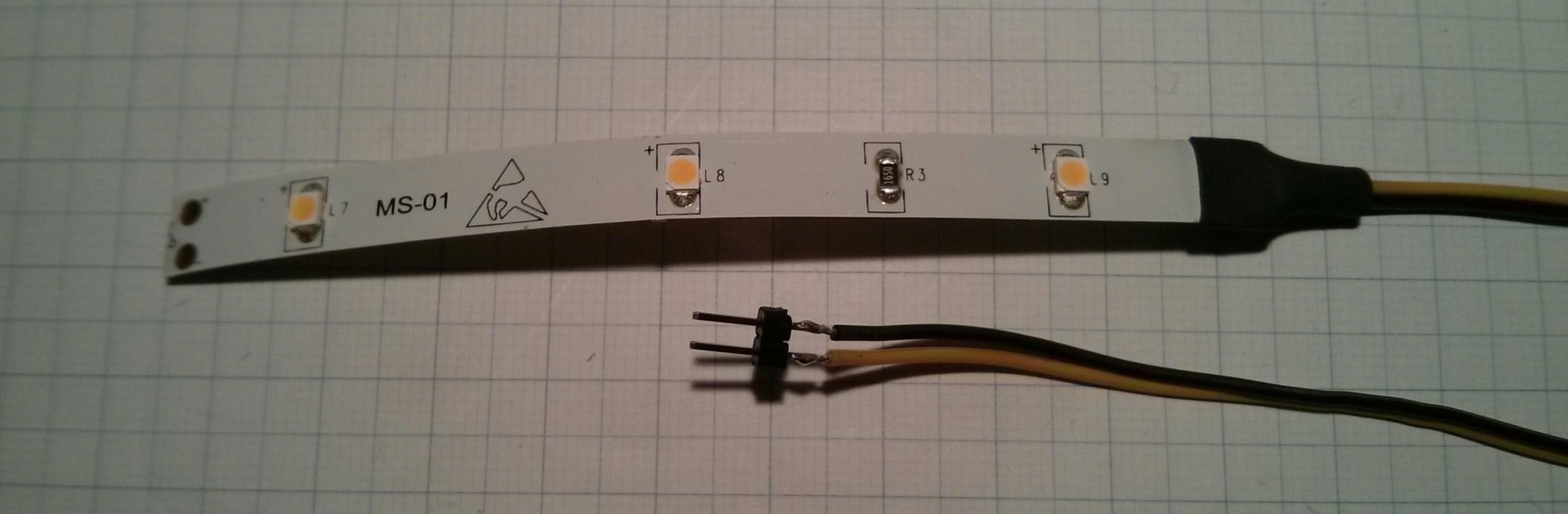
From converting my broken desk lamp to LEDs I had some leftover pieces of LED strips that just seemed perfect for this purpose so I did a quick test and soldered up this prototype:
![]()
The two pins just plug into the 4-pin Berg connector from the PSU so the light is on whenever the PSU is on. But since the amp meter is only needed when the adjustable voltage part of the power supply is used I might add a switch or tie it some other way to the variable output.
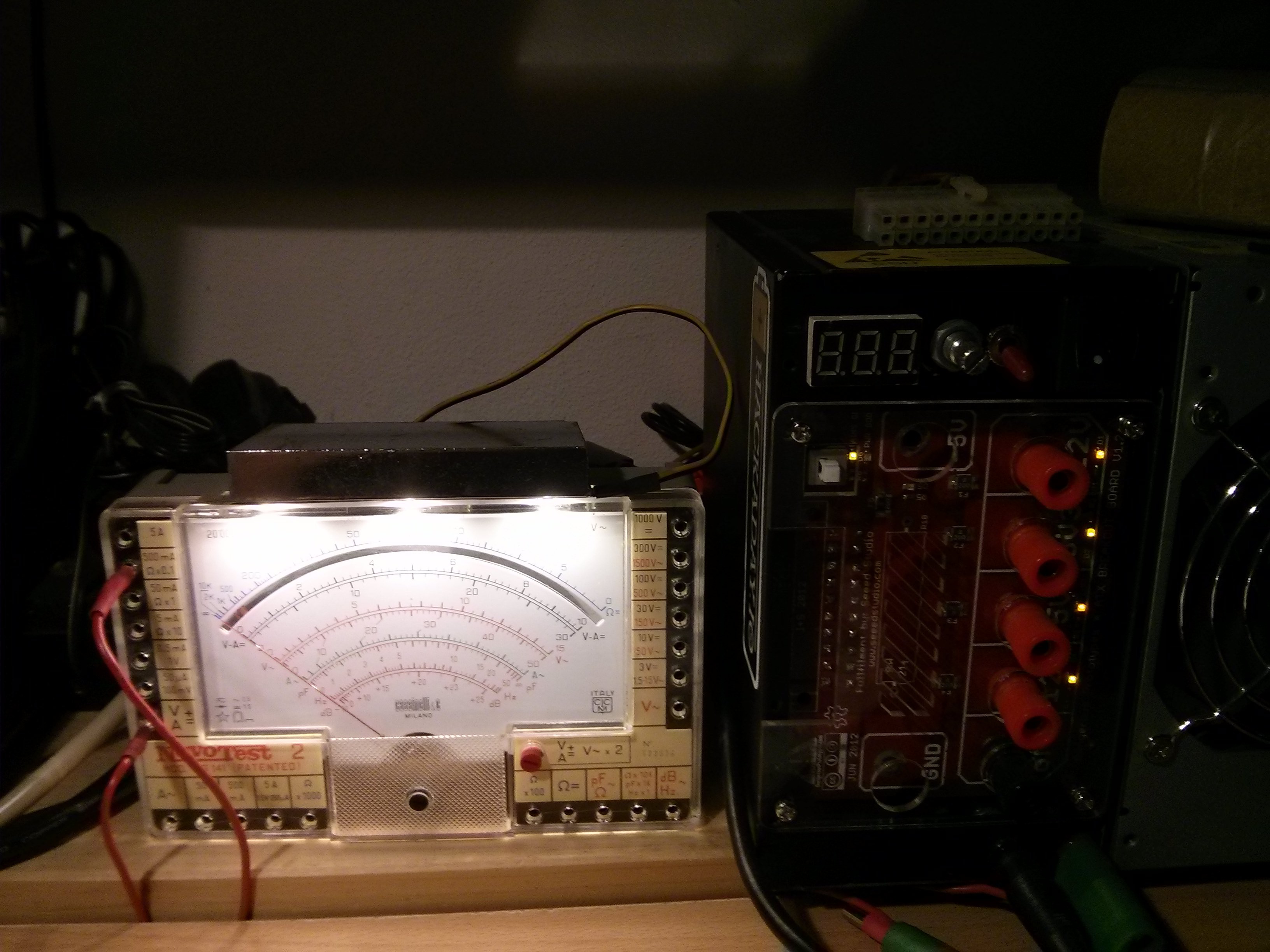
This is really a very trivial mod so the main reason for this log is that I was just way too pleased with the result:
![]()
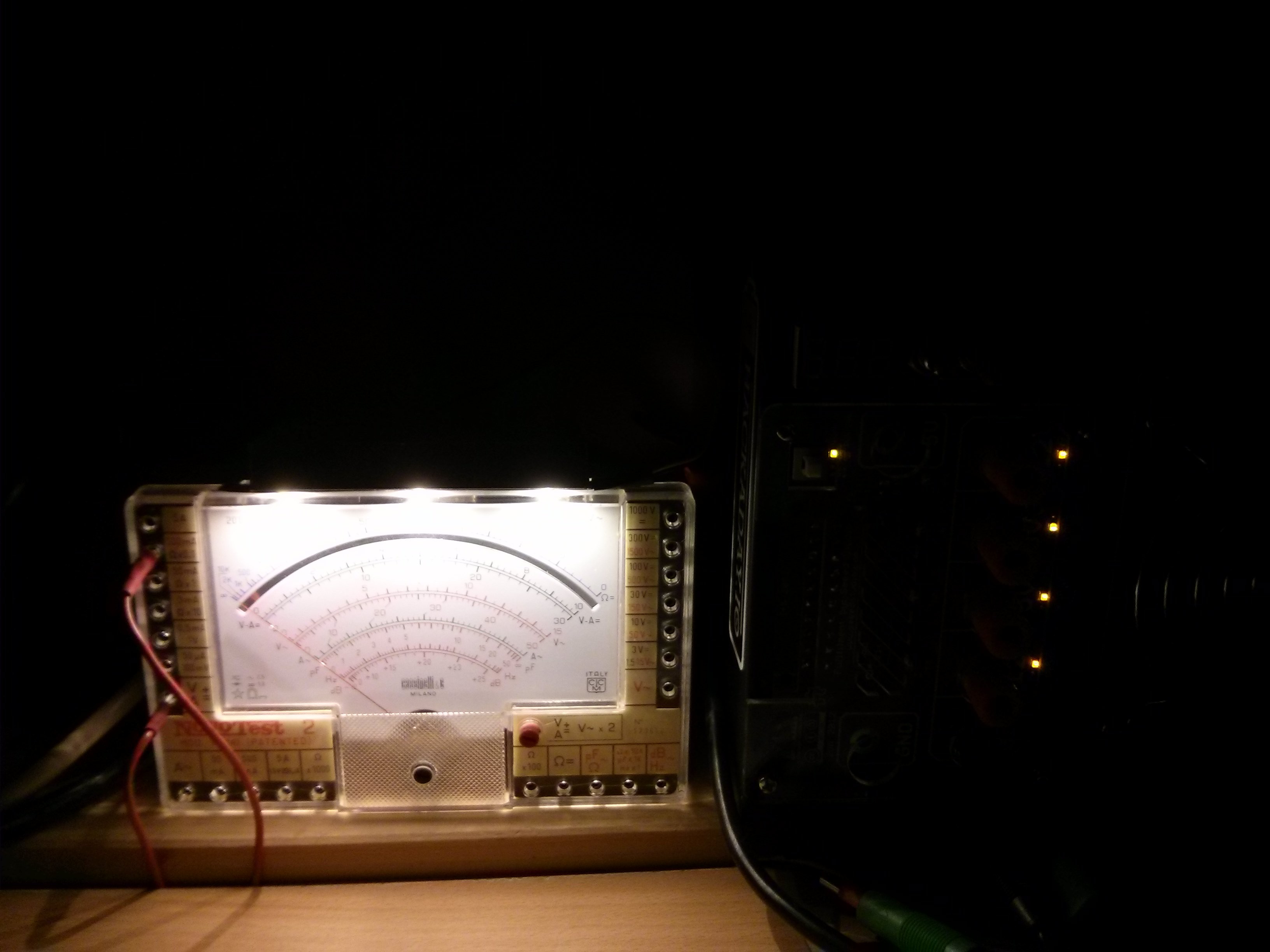
And this is how it looks with the lights turned off:
![]()
...
As I said, I was just too pleased with the look... contrary to the modified lamp which once done looked pretty much like before, where's the excitement in that?
-
The (in)complete list of ATX PSU projects to rule them all
02/15/2015 at 14:11 • 0 commentsHere are a couple of links that I found useful. I'll update the list as I find new sites and please let me know if you know projects that should be listed here as well.
Let's start with HaD.io projects. A quick search results in
- #ATX power supply conversion for bench usage
- #ATX Benchtop Power Supply
- #Bench Power Supply - ATX PSU Adapter
- and you might also want to check out @davedarkos take on the topic here, here and here
For the next links there's probably going to be some overlap with references from the above projects but I'd like to mention them nonetheless.
If you have googled the topic you might have come across Phil's video about the topic. There's also some more information in the video description. While on the topic of videos, this one makes a good point why a conversion might not be the best idea.
Now for some detailed tutorials over on intructables:
- Very nice build in a case with swappable PSUs (I think this one was featured on HaD)
- A minimalistic approach
- More tricked out with adjustable voltage
- This one has a lot of information on the topic
- Based on a breakout board
- I really like the form factor of this one
These are some links that might be useful for adding features like adjustable voltage and digital control:
- http://www.instructables.com/id/How-to-Build-a-Bench-Top-Power-Supply/?ALLSTEPS
- http://www.instructables.com/id/Variable-0-12V-Digitally-Controlled-Power-Supply-u/?ALLSTEPS
- http://www.instructables.com/id/Mini-adjustable-power-supply/?ALLSTEPS
- http://www.instructables.com/id/DIY-Small-Bench-Power-Supply/?ALLSTEPS
- http://www.instructables.com/id/Mini-Adjustable-Voltage-Regulator/?ALLSTEPS
This post about the efficieny of switching voltage regulators is also quite interesting.
-
Cheap two lead voltmeter mod
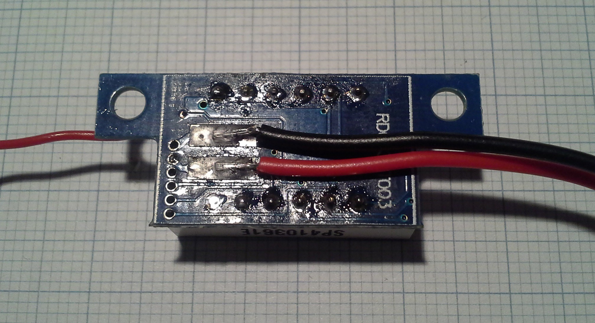
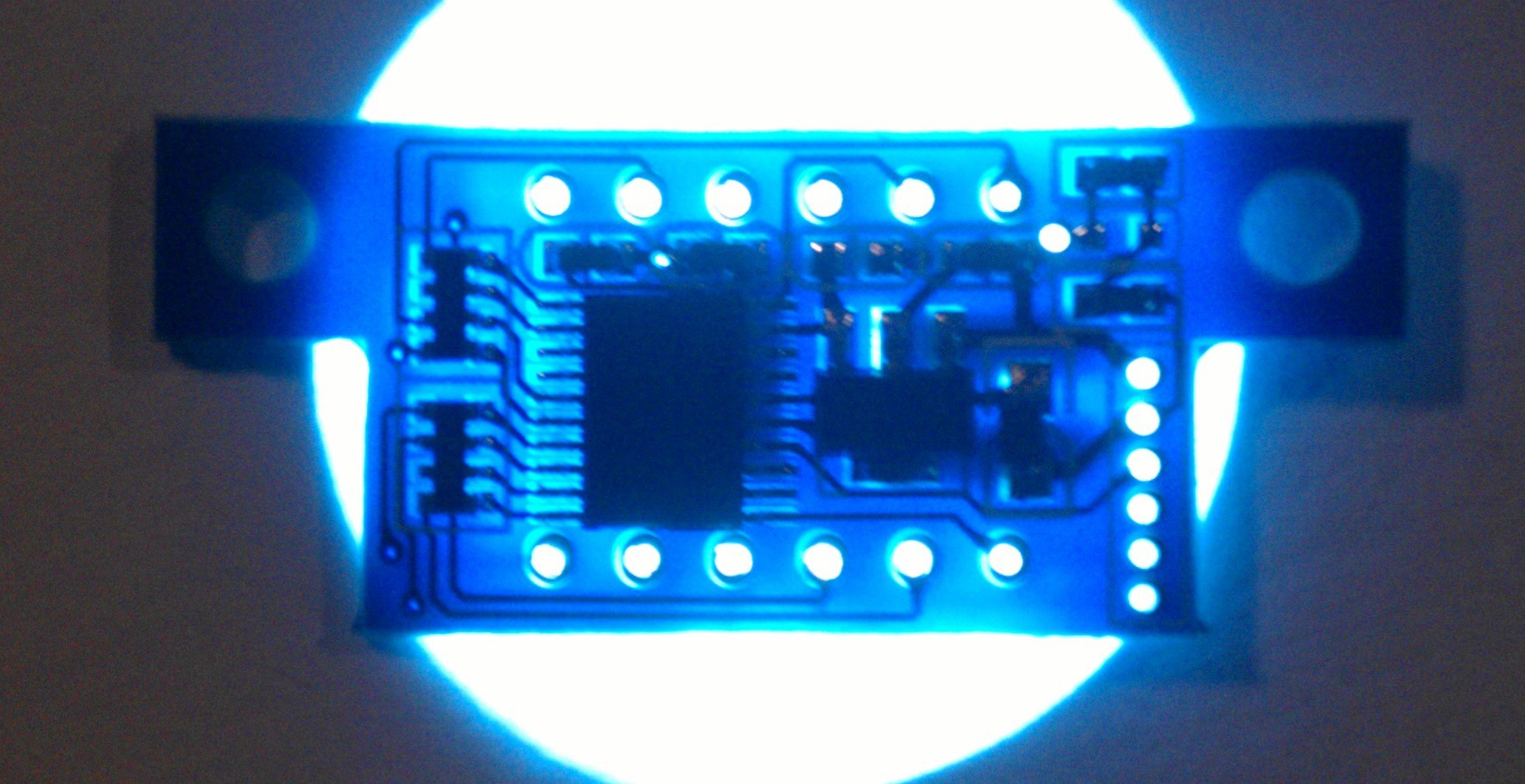
02/15/2015 at 00:20 • 11 commentsFor my first PSU build I used one of these cheap LED voltmeters that you can get from eBay for less than 2€. The ones I got have a measuring range of approx. 3-30V. The lower boundary is due to the fact that these meters measure their own supply voltage.
![]()
Unsatisfied with this lower boundary I analyzed the 2nd meter I ordered as a spare to see if there was something I could do. With only half of the PCB visible I first desoldered the display and in an attempt to view both layers of the PCB I put it on a lamp:
![]()
... with arguable success... looks nice though. However, it actually helped seeing the traces on the side I was looking at since the silkscreen concealed some of them.
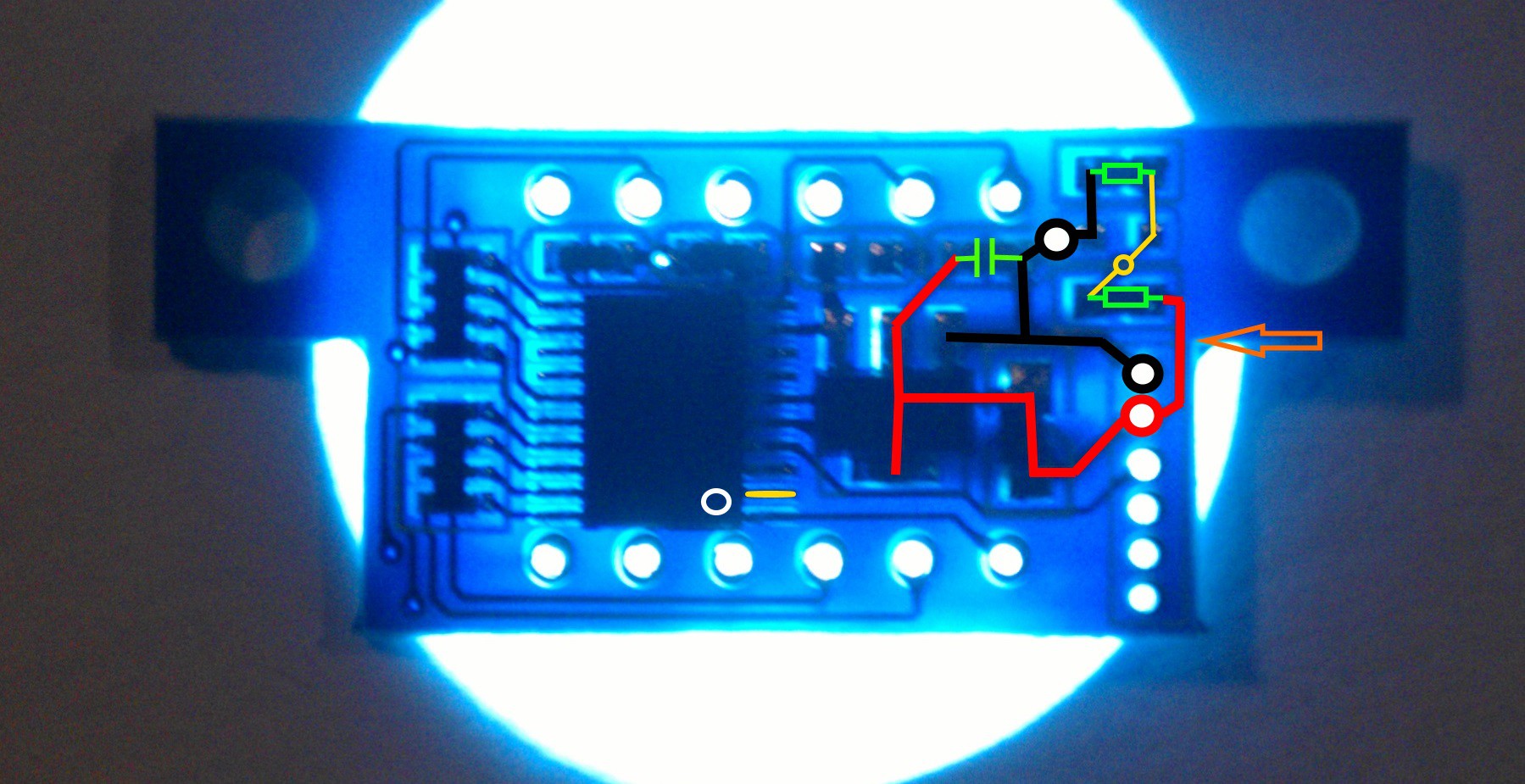
Anyway. I could now follow the input voltage to the voltage regulator and to a voltage divider.
![]()
The center of the voltage divider (yellow section) first goes to the other side and then to another via under the MCU. Checking the continuity shows that it's going to pin 2 (with the marking for pin 1 being in the bottom right). In order to separate supply and measured voltage I simply cut the trace between the voltage divider and the supply voltage (orange arrow) coming from the other side and made sure the connection was severed. The first (high side) resistor of the voltage divider right above the orange arrow also made a good point to solder a wire to for the sense voltage.
With this voltmeter I was even able to perform this modification without taking off the display. Cutting the trace at the very edge was easy while soldering a wire to the resistor was more difficult.
In summary the basic gist is to first identify voltage regulator and divider, cut the trace and then solder an extra wire to the voltage divider. Depending on the model of voltmeter you have this might not be feasible without disassembly and on others where the components are on the the outside it might be even easier.
-
ATX Bench PSU v1
02/14/2015 at 21:42 • 0 commentsBefore starting the project I did some research and found many great instructions so I'll not go into detail about the topic but rather share some pictures and comments.
![]()
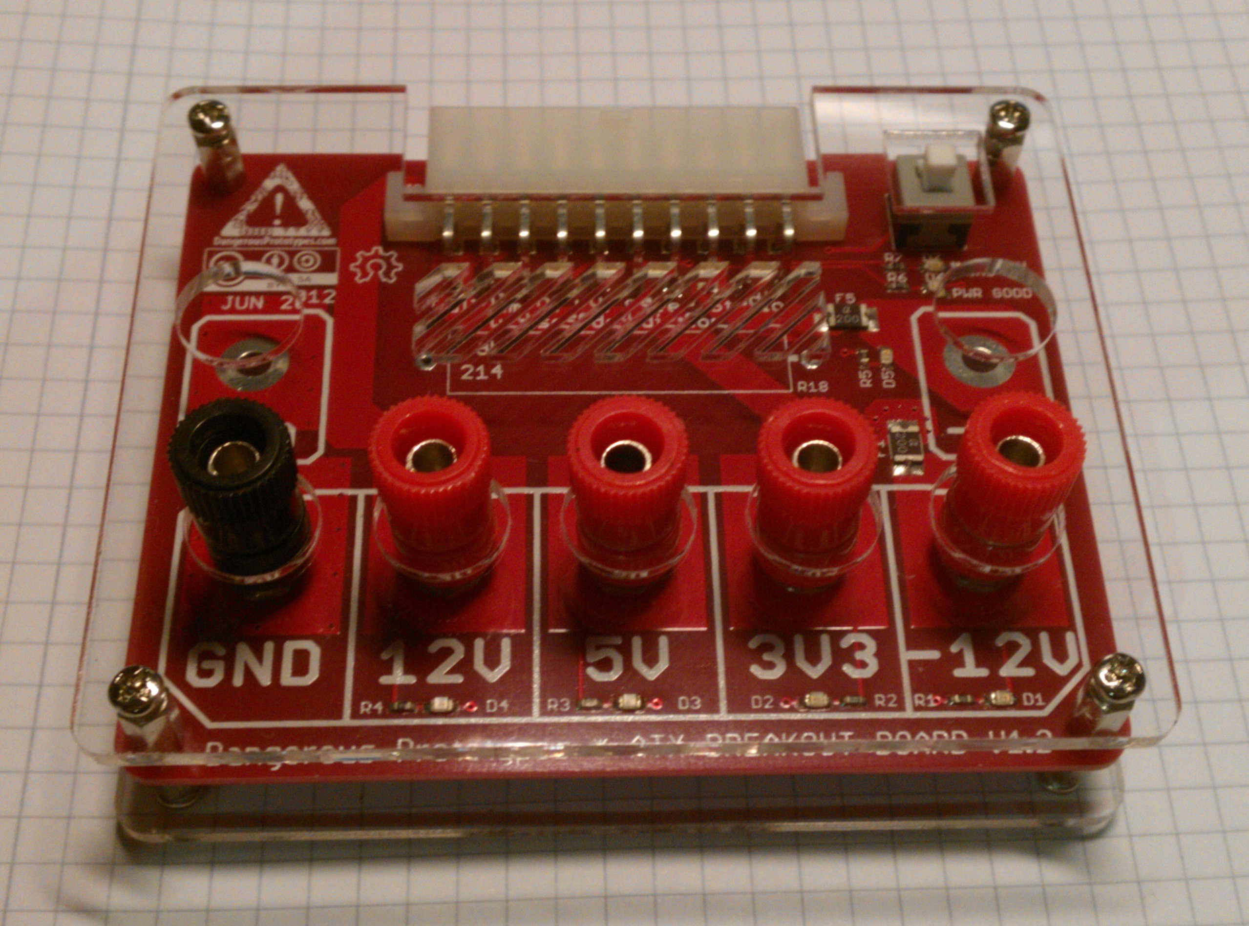
After using an Arduino or even a programmer to power my projects on a breadboard there came the time to move on. I liked the idea of using an old ATX power supply mainly because it was a cheap solution and I don't have the need for something more sophisticated as of now. I didn't really want to do a proper conversion, in the sense of adding binding posts to a PSU, due to the fact that if the power supply failed the work would have been for nothing. Therefore I took the easy way and bought an ATX breakout board so in case of a failure simply swapping the PSU would solve the problem. Specifically, I used the Dangerous Prototypes ATX Breakout Board. (There's also one from Sparkfun)
![Dangerous Prototypes ATX Breakout Board]()
Using this board has the advantage that it's basically a complete ATX power supply kit and I didn't have to worry about choosing proper power resistors since I trust DP when they say they aren't needed in most cases. The fuses are a nice feature, too, and if I need more than 1A of current I can still tap into the Molex connectors. The only downside was that the 20/24 wire mainboard connection is quite rigid which hardly lets the breakout board rest level on a table. Therefore, by mounting it in a case I could have it stay in the same place and also add some features. Well... one feature. By adding a LM2596 switching voltage regulator board and a voltmeter the PSU can also supply a variable voltage. With a slight modification to the cheap voltmeter it's even possible to measure voltages down to 1.2V but more on that in a separate log.
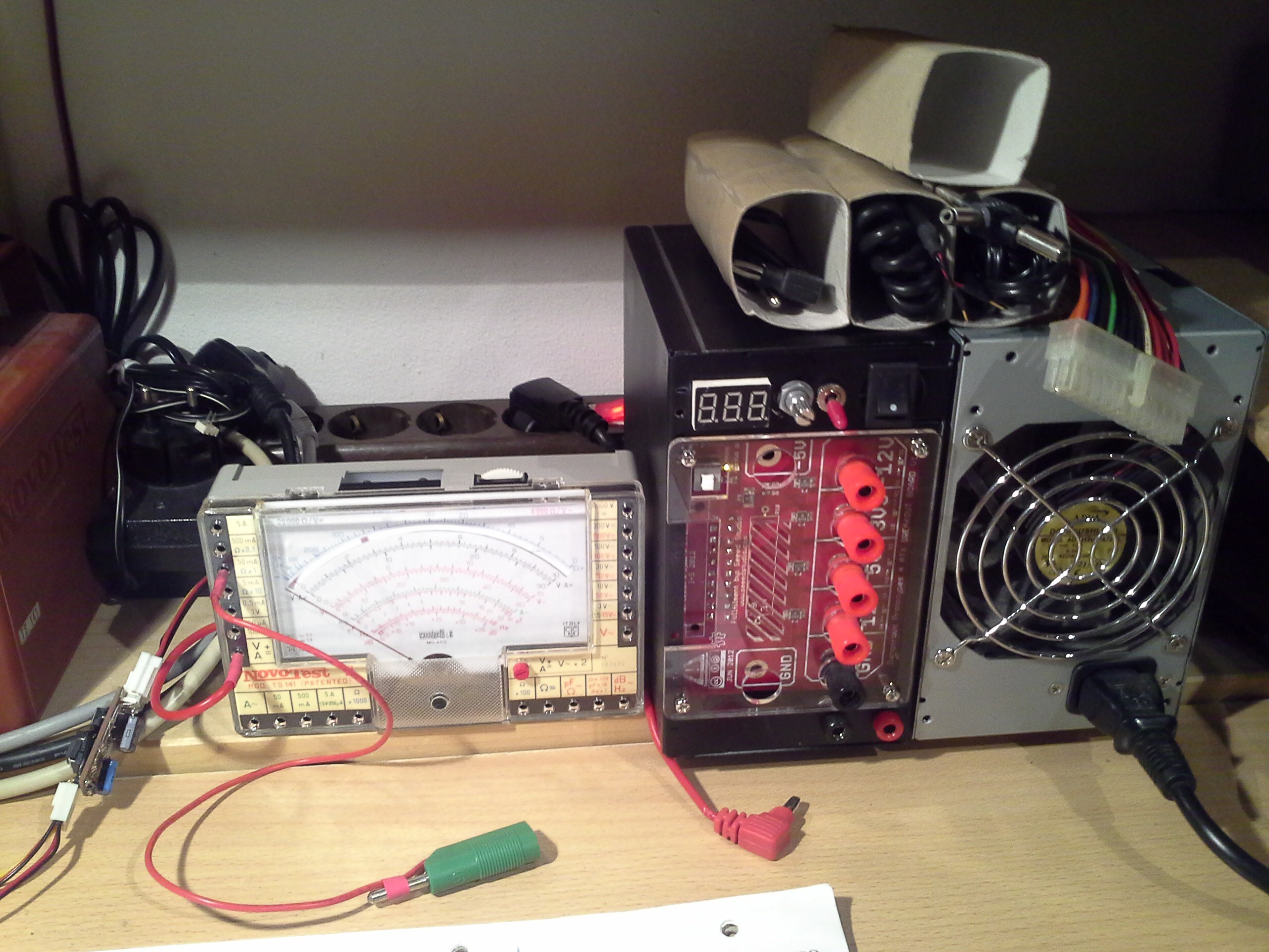
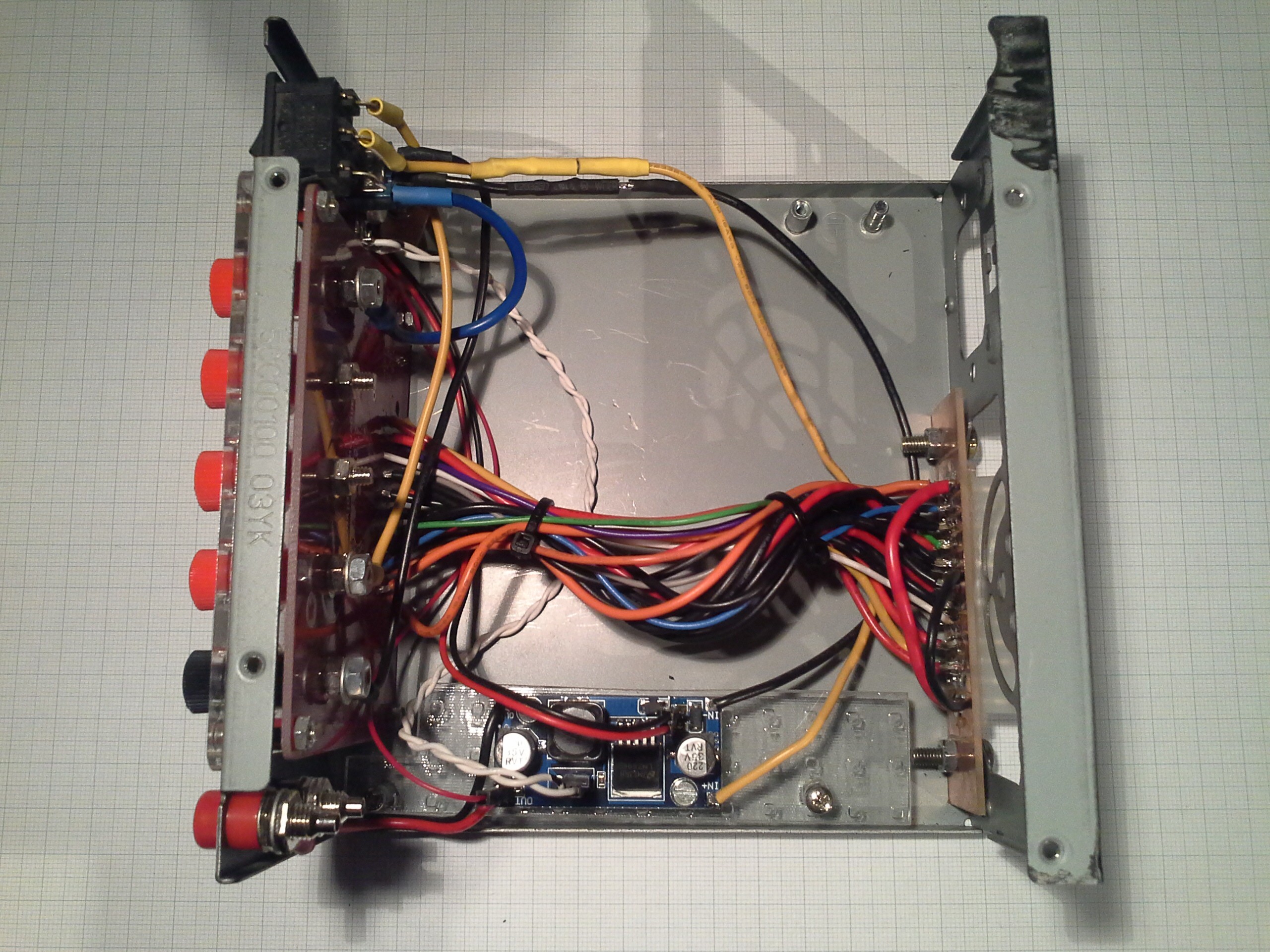
![]()
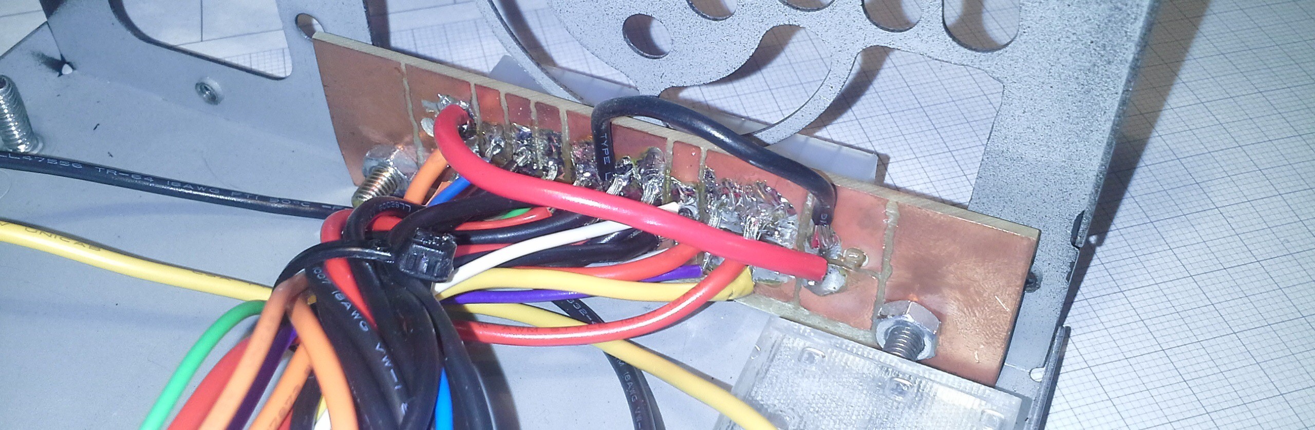
As you can see in the pictures, hooking everything up is pretty straight forward: The PSU attaches to the (modified) breakout board and the voltage regulator to the breakout. For the breakout board to be used in a case (an old ATX PSU case) I needed to move the 24 pin connector to the back of the case (or at least to the back of the board, which will be possible with the next version of the DP breakout board). Due to the lack of a CNC router and motivation to order a PCB I threw together this circuit board made from copper clad board machined with a rotary tool.
![]()
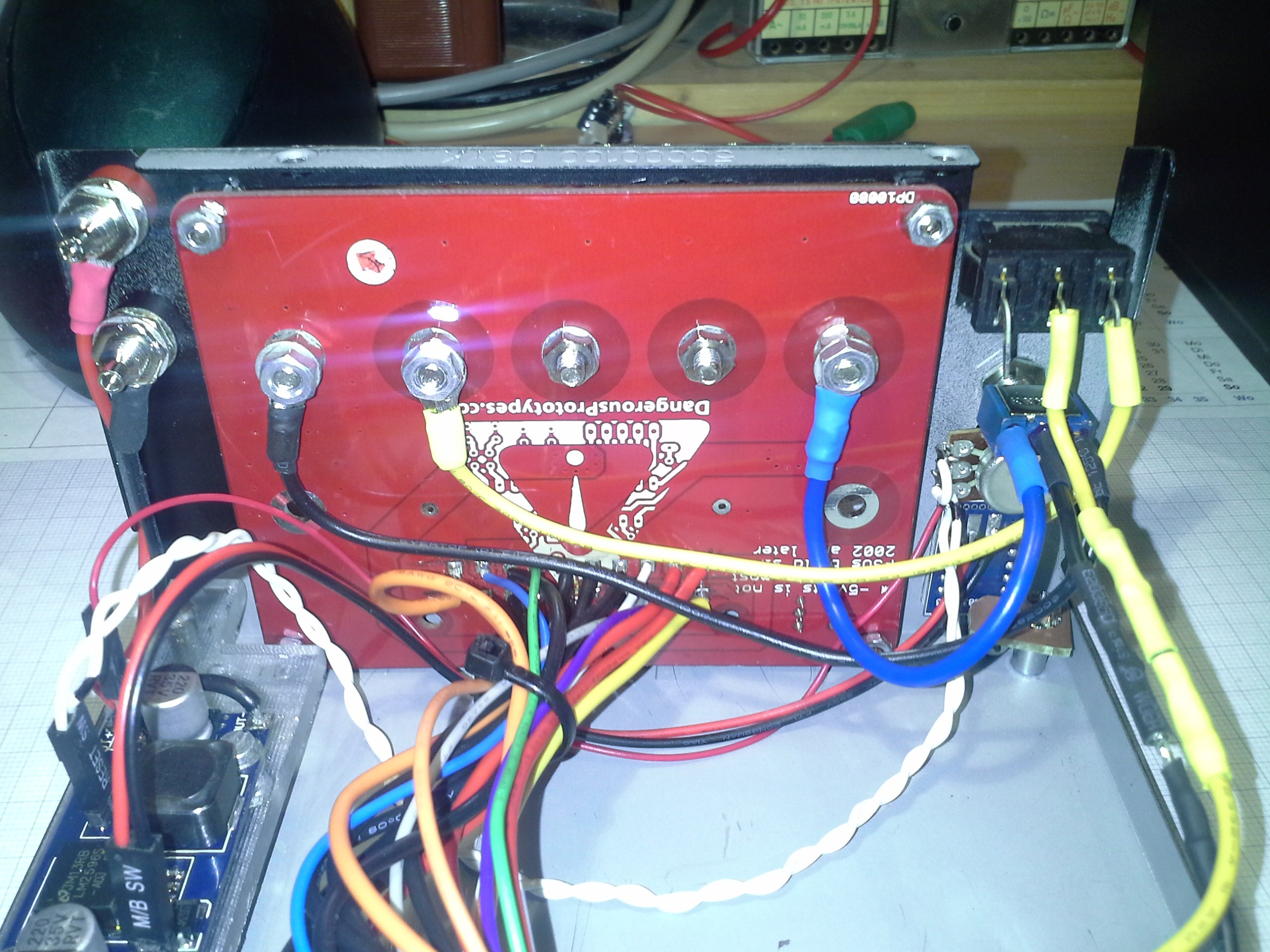
Obviously the outputs of the voltage regulator go to two banana sockets but for the inputs I chose to connect the positive input to the 12V rail via a switch to turn it off and on. The negative input however, can either be connected to GND or -12V to get a larger voltage range although with lower amperage. In order to control the voltage from the panel it was necessary to remove the onboard potentiometer and replace it with one that can be mounted to the case. To do this I added pins for the pot and also for the in- and output voltages with the latter ones being for the voltmeter.
![]()
Conclusions
Initially I was hesitant to completely build this ATX conversion myself since there are some variations among all instructions, mainly regarding minimum loads, but when looking at the schematics of this breakout board it's actually straight forward. Therefore, in v2 I'll probably design a PCB similar to DP's v2 with the binding posts and 24 pin socket being on opposite sides.
The LM2596 module works great. However, recently I've found myself in need of current control which is why I'll use a different module of this type next time. This will of course also require an amperemeter, which is why a combined voltage and current meter will probably be the better choice.
The potentiometer I used here only allows for about 300° of rotation. This makes precise setting of a voltage between 0V and 12/24V quite difficult (but not impossible). A better option would be a pot with 10 turns of travel like this one.
As you saw, there's a lot of space left in the case so a smaller case should do in the future. I'm thinking about building something that would attach to the ATX PSU like this.