 Kayser-Sosa
-
11Step 11
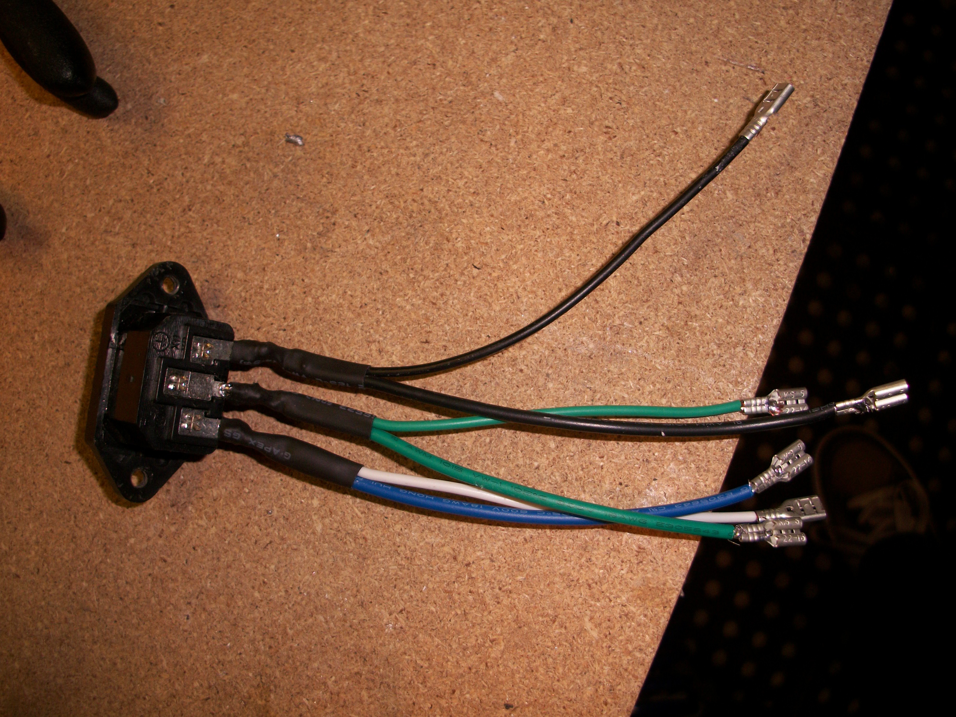
Mount the power input.
I used the power connector from the PSU and double wired it so it ran to the PSU and the LCD. I used quick connects so I could remove as much wire as I wanted and still be able to remove the LCD and PSU without having to remove the power connector in the case. So the metal of the quick connects didn't short out, I wrapped them in electrical tape once connected to the LCD and PSU.
![]()
-
12Step 12
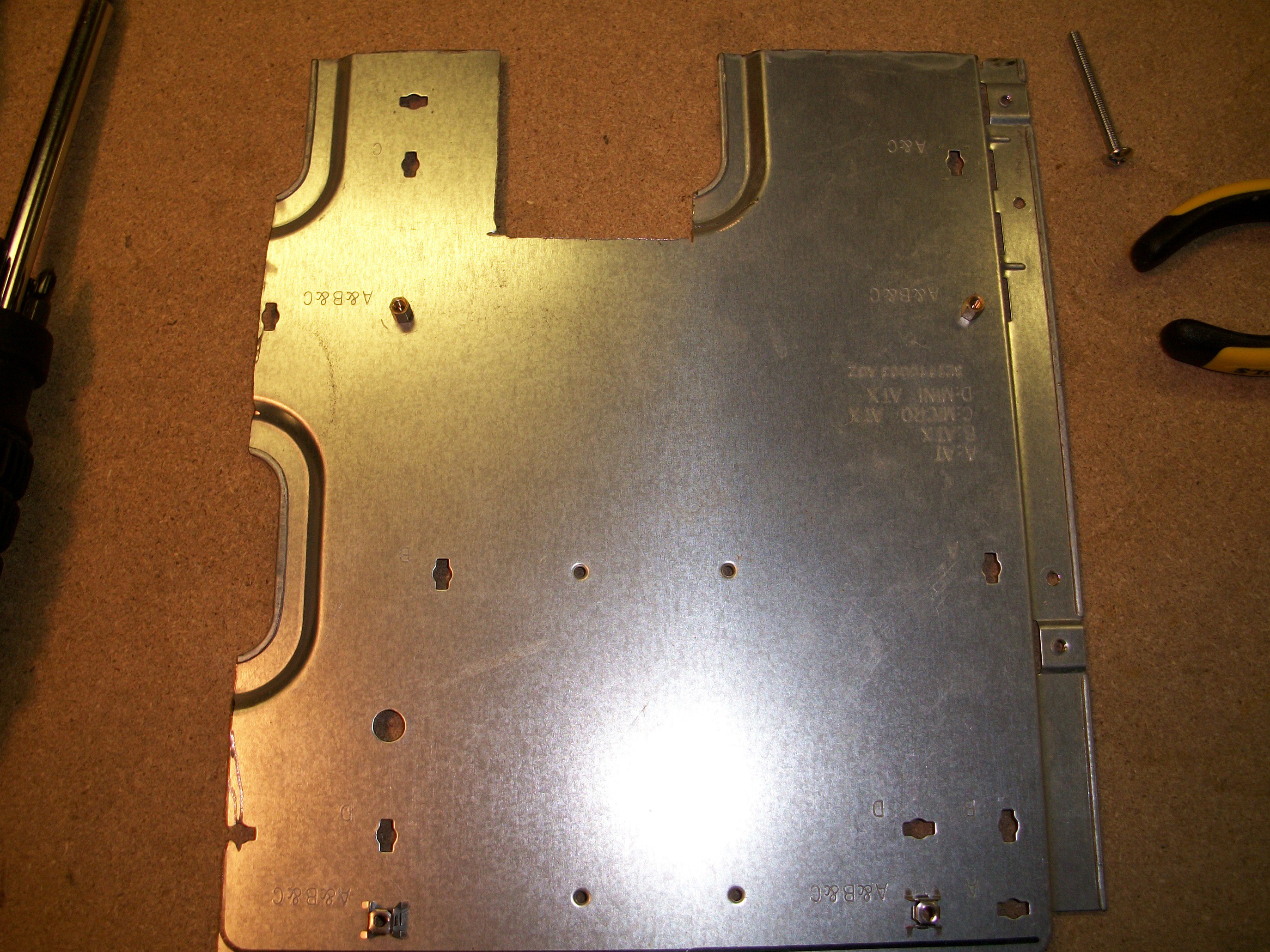
Motherboard mount.
I had an old case laying around so I cut out the motherboard back plate and cut it down some more to mount my mother board on. My friend put his motherboard raisers directly in the wood of the case.
![]()
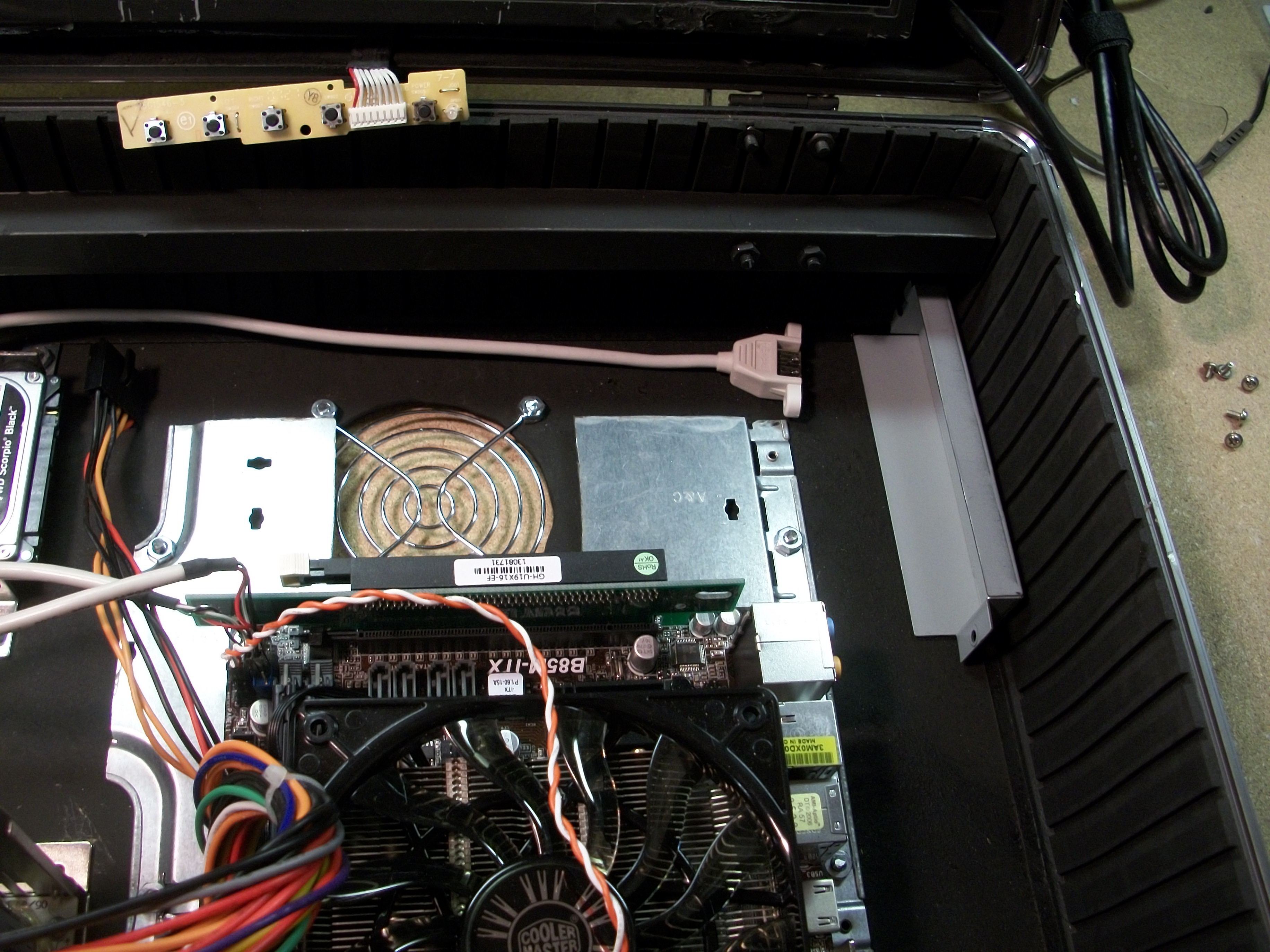
The partial square cut out at the top is for the GPU fan. I put the GPU on a left L-connector to the motherboard so the fan faced down. I put the motherboard and GPU on the back plate so I could find the location inside the case to mount it correctly. I secure the back plate to the case and mounted the motherboard normally. I had to remove the faceplate of the GPU and create a support since it was on the L-connector. I just cut up the GPU faceplate a bit and used the existing screw holes on the GPU to support it.
![]()
-
13Step 13
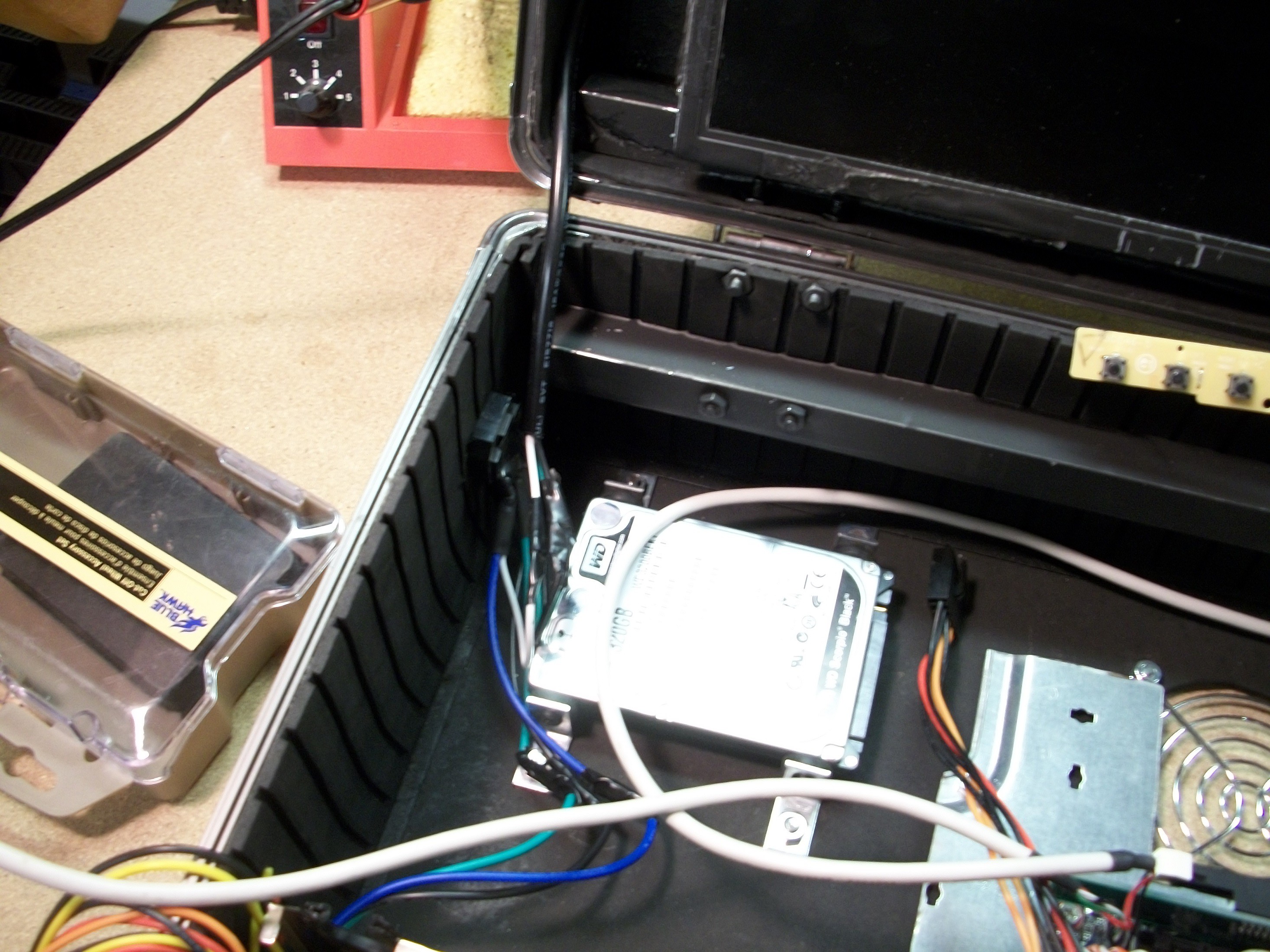
Mount the HDDs.
I started with only one HDD and added another later on. I used L-brackets, one at each of the four corner screw holes of the HDD and attached the L-brackets to the HDDs with Evercool UVS-01 Anti-Vibration HD/Fan Mount pieces between the HDD and L-brackets.
![]()
-
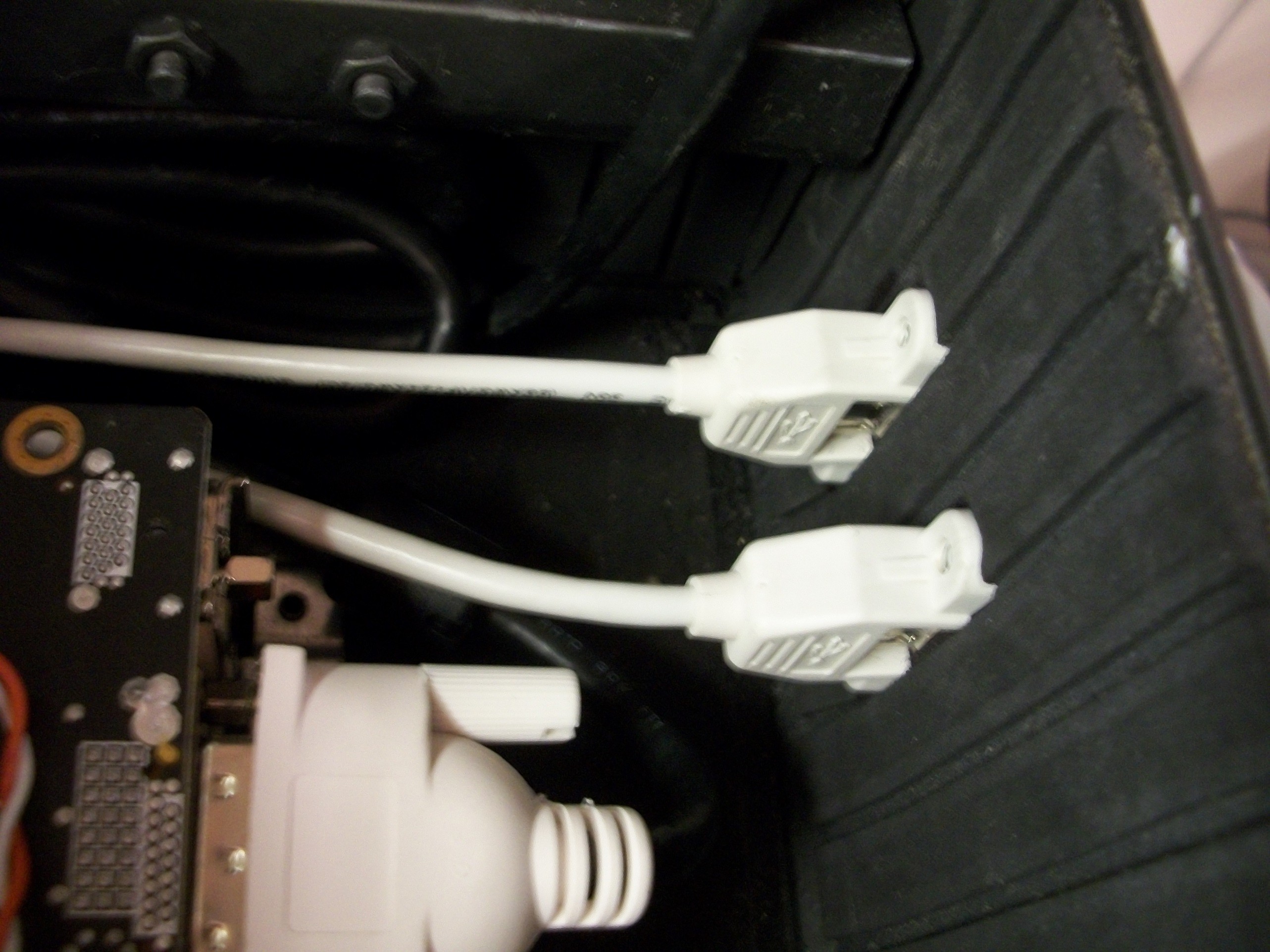
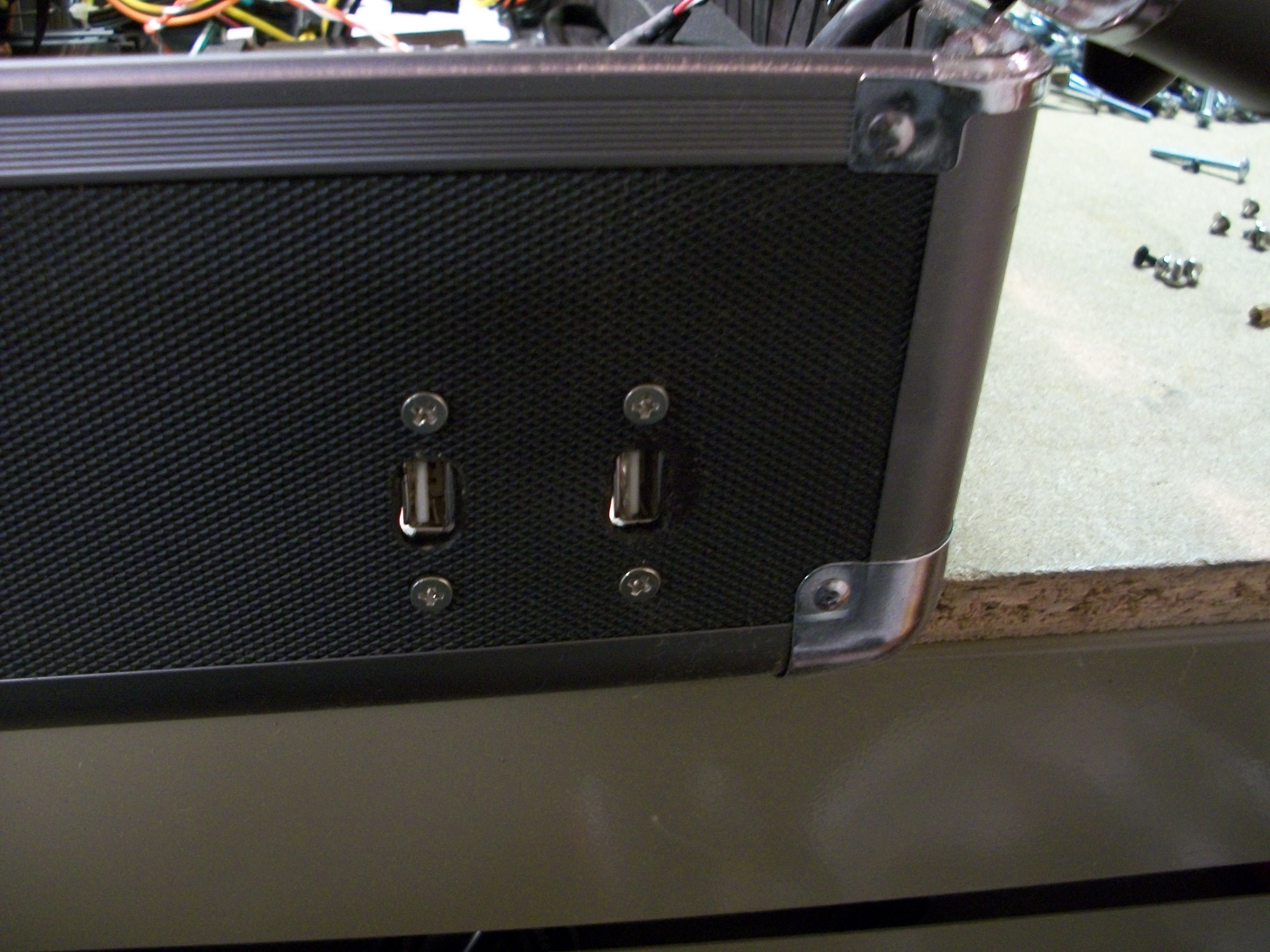
14Step 14
I ran all the needed wires, such as the USB on the right side.
![]()
![]()
-
15Step 15
Initial acrylic work.
I started on the acrylic next, after verifying everything was fully functional. There was a lot of trial and error, measuring several times before cutting the acrylic.
I used a dremel and a straight edge for most of the cutting, making patterns for the interior items and cutting them small at first so I could increase if needed. I did patterns for the fans and used a circle cutter attachment for the dremel to cut them as neatly as possible. L-brackets and Velcro hold the acrylic in place. I put L-brackets around at weak points and let the acrylic sit directly on top of the fans. It isn't perfectly level, but it is close. I recommend pre-drilling anything you plan on screwing in, as I ended up cracking the acrylic in a few locations because of it. I used electrical tape to help keep things in place, and have yet to replace it. The right side I made a flip up section so you can get to the ports on the "back" of the motherboard and later when I added the hinge cut a space out for it.
![]()
-
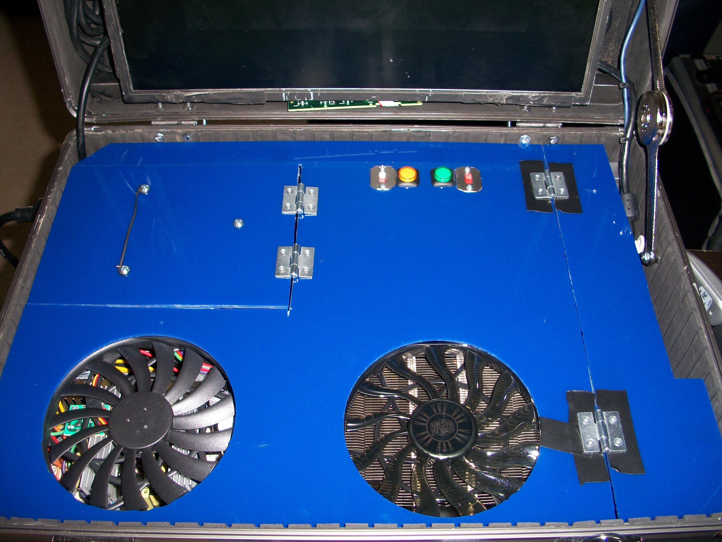
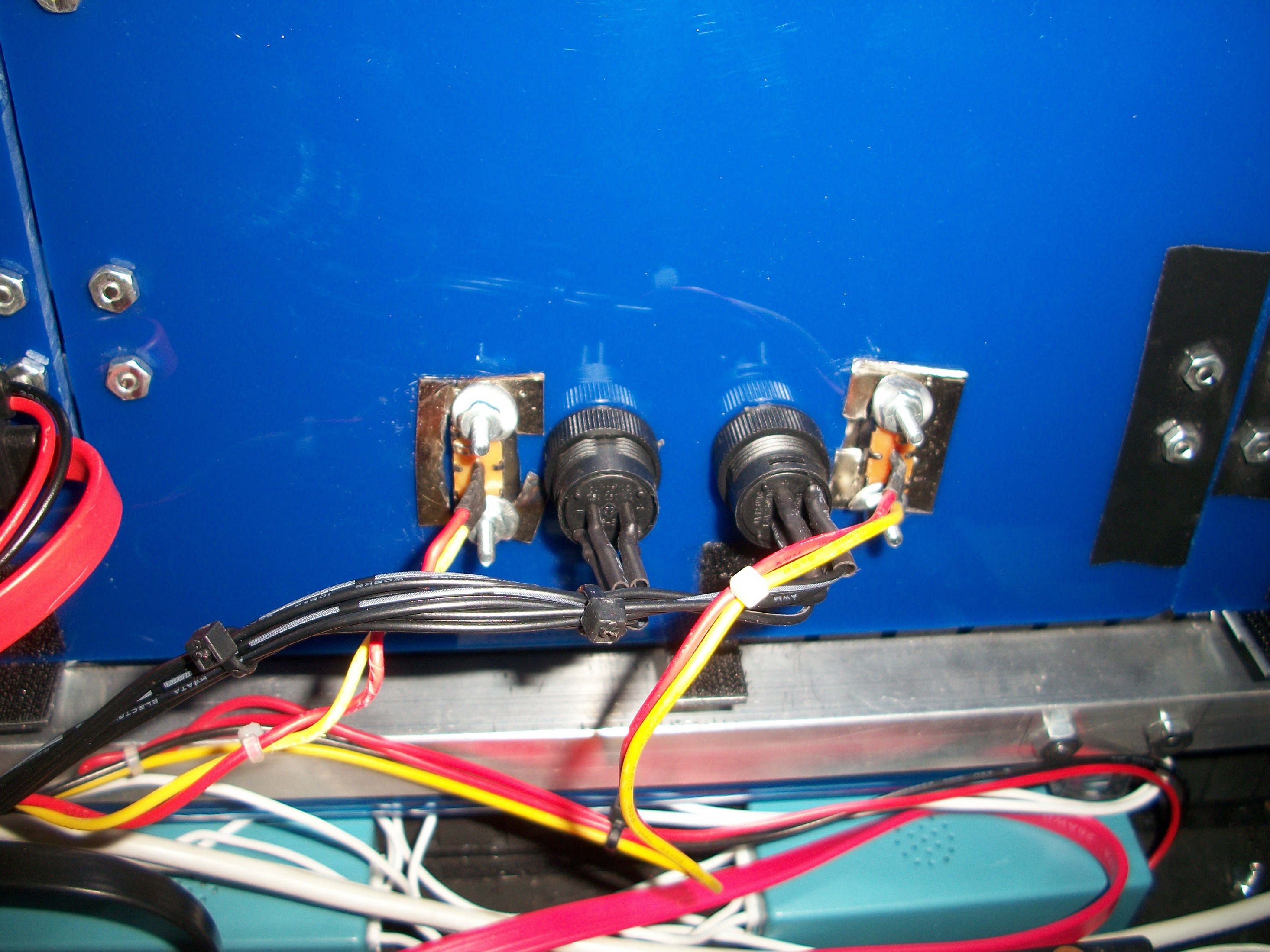
16Step 16
Additional acrylic work.
I worked on mounting the power and reset buttons, and cathode light switches next.
![]()
I drilled holes for the power and reset buttons and used a dremel for the cathode light switches. I had to cut up some metal scraps to help hold the cathode switches in place. I could have left the switches off the acrylic since I leave them on all the time anyway.
-
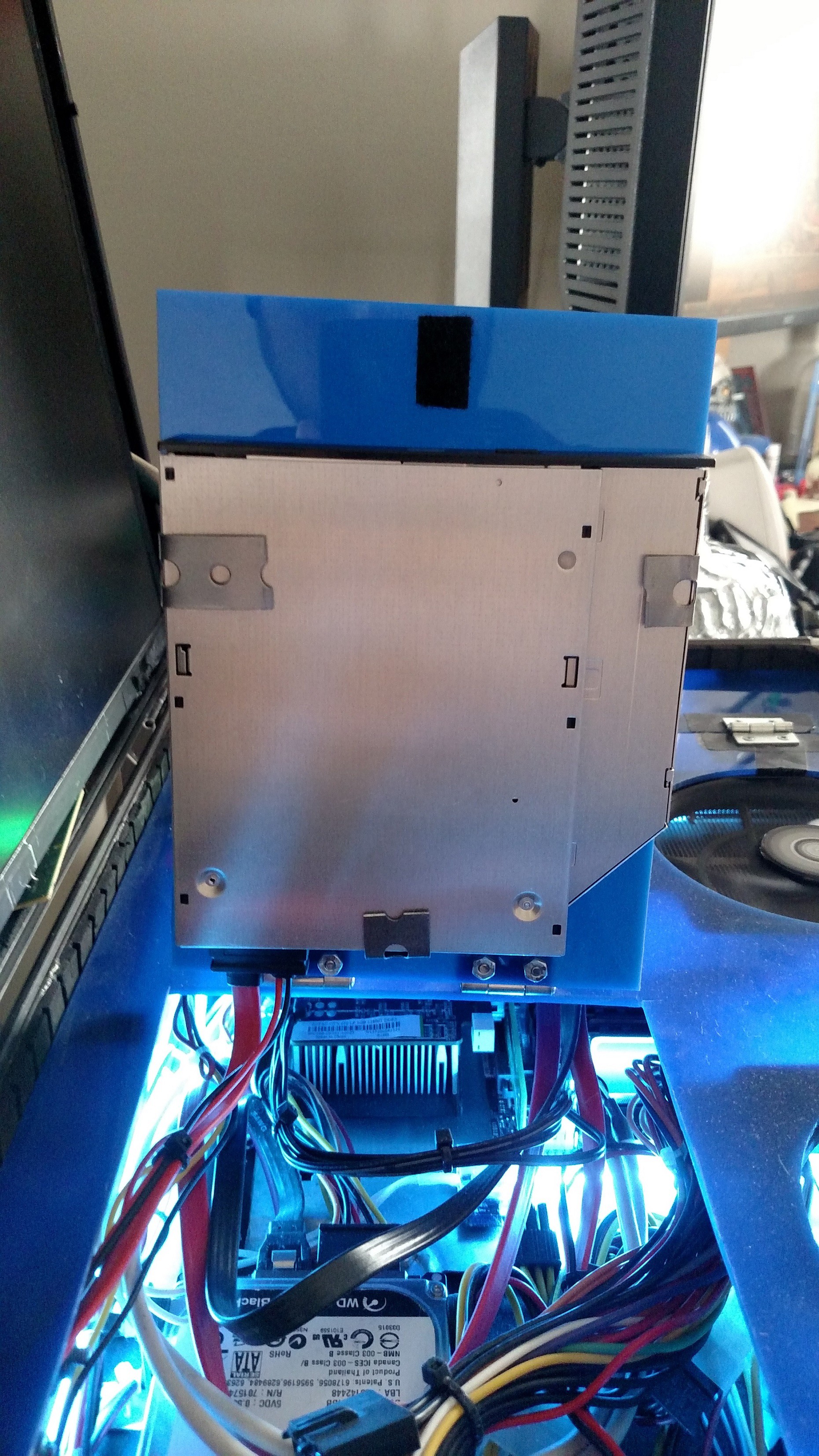
17Step 17
Optical drive mount.
The optical drive took some thinking on how to mount it, since there aren't any screw holes on it. My first attempt on my prior case I cut a hole in the side to allow the drive to open and close. I didn't have a framing piece so it ended up looking like a ugly cut in the side.
I ended up using some metal hanger straps that I had laying around. I folded them around the drive and screwed in the top of each side and one around the back of the drive.
![]()
-
18Step 18
Cold cathodes mounts.
I add the cold cathodes to any location I could find room, they aren't necessary but look cool when playing in the dark.
-
19Step 19
Speaker.
I use one of those puck speakers and it works very well. I have it plugged into the audio port and it is USB rechargeable so I just leave it plugged in to USB all the time.
-
20Step 20
I have a USB wireless dongle, that I keep changing as I find faster ones.
Briefcase PC
A portable desktop computer, complete with monitor and a single power plug.
Discussions
Become a Hackaday.io Member
Create an account to leave a comment. Already have an account? Log In.