NPN
NPN-
Conclusion
01/28/2018 at 00:54 • 0 commentsFinishing
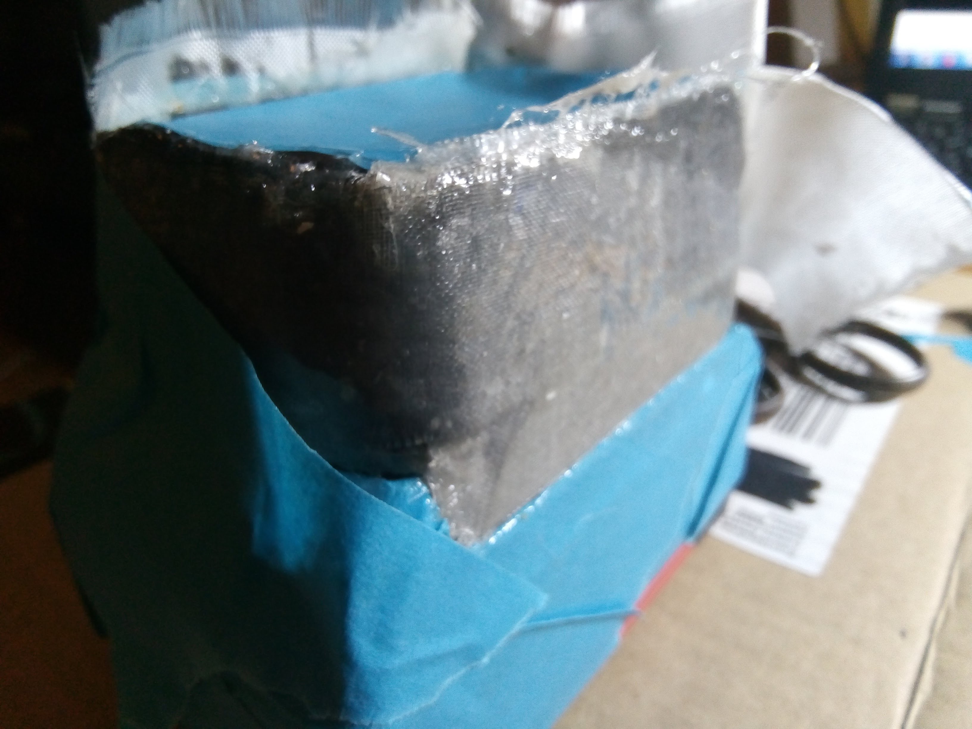
I used fiber glass mat and epoxy to make a clean surface. I don't know how the glue will hold up. So over engineer it !
![]()
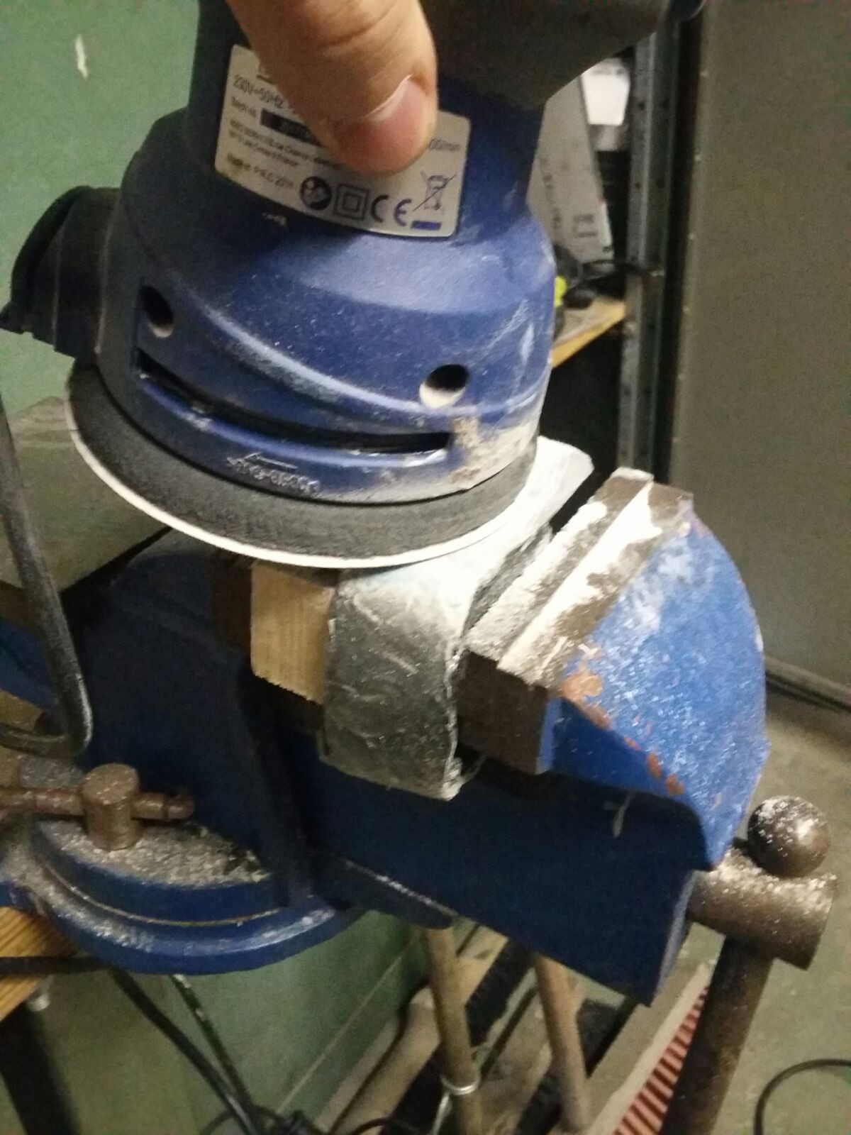
I sanded it :
![]()
![]()
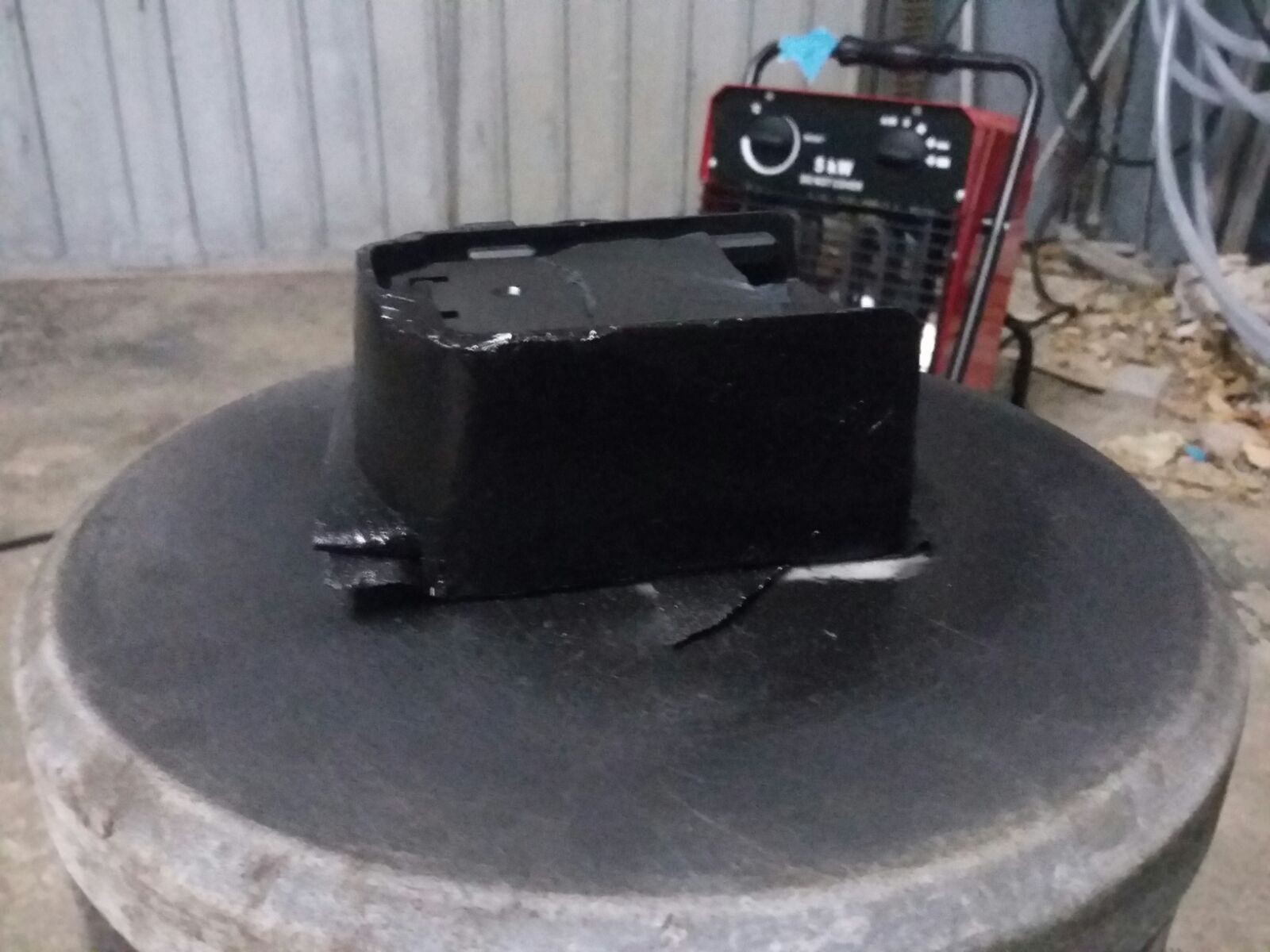
I painted it in black with paint laying around :
![]()
![]()
![]()
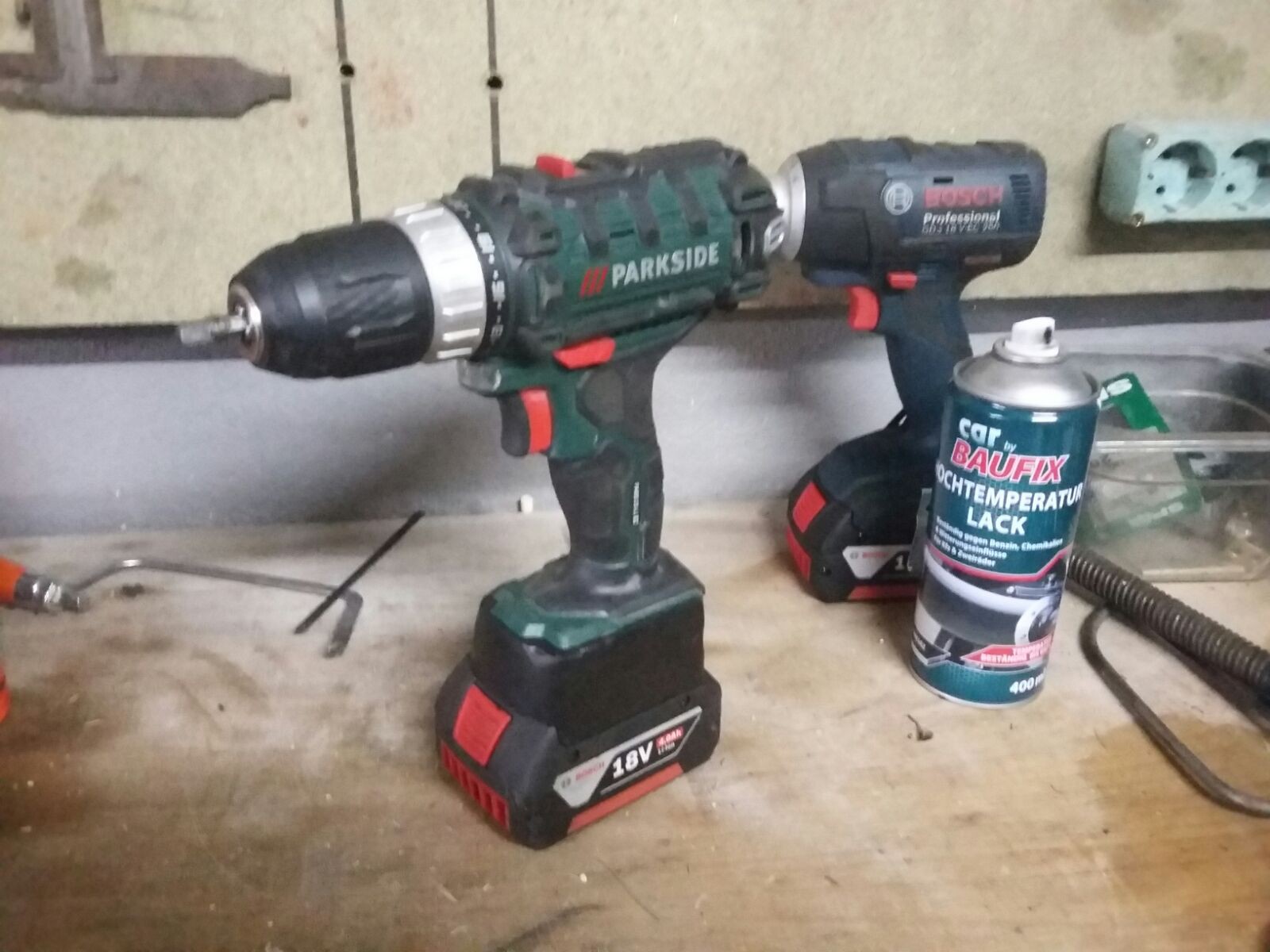
Conclusion :
My drill is working great, has a bit more torque as far as I remember, and use the same battery as the other tools. It's really great !
If I had designed the 3D from scratch I could have used just one 3D printed piece, but less work is better.
Quid of the project 4€ for the glue, the rest was laying around in the workshop.
-
Meeting in the middle
01/28/2018 at 00:38 • 0 commentsThis time we'll assemble both parts.
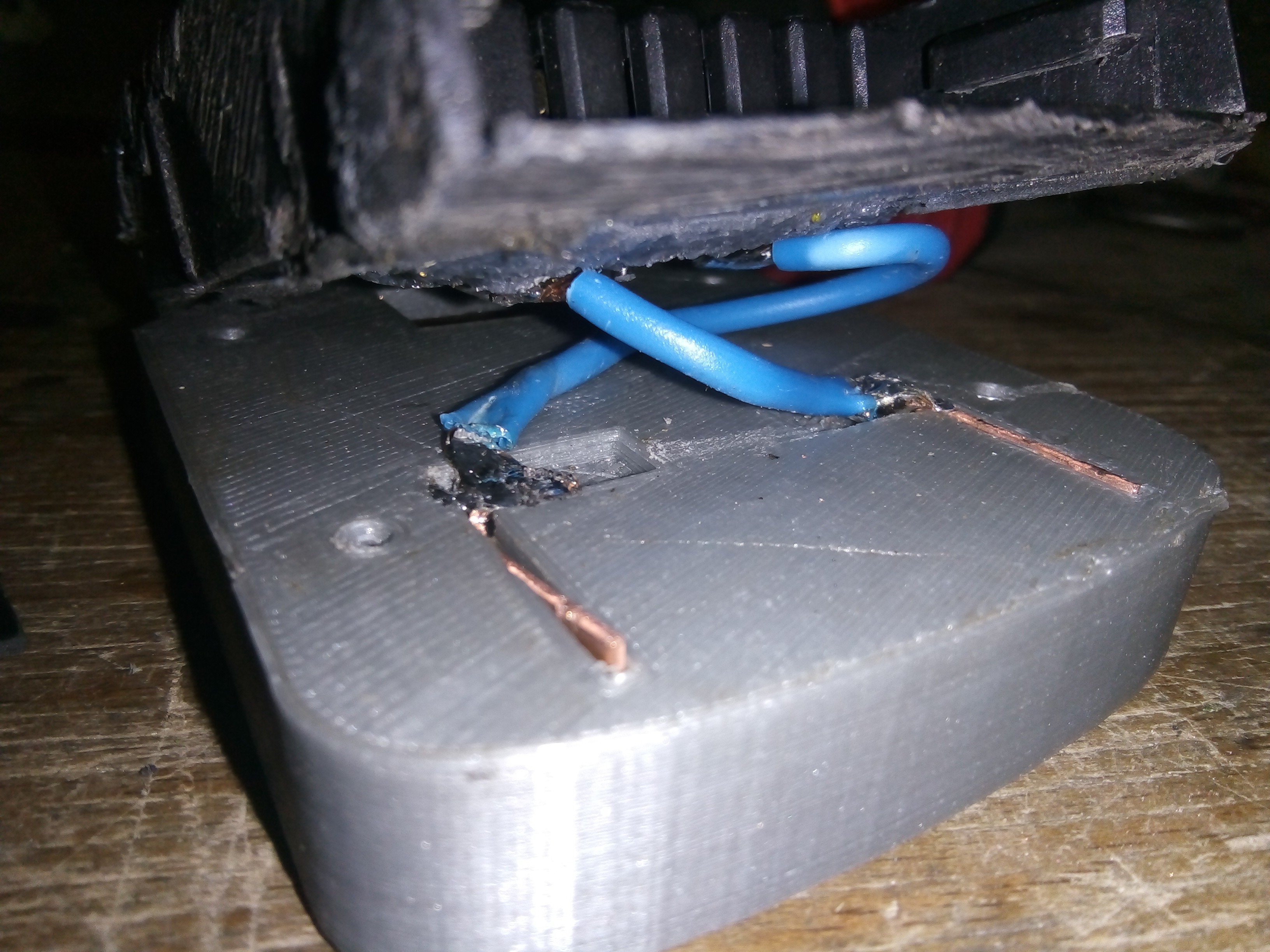
Before soldering check the polarity !
In my case reversed from Bosch to Parkside : (see the wires crossed)
![]()
If the polarities are not on the same side it will need some electrical insulation :
![]()
Place glue and let it cure :
![]()
![]()
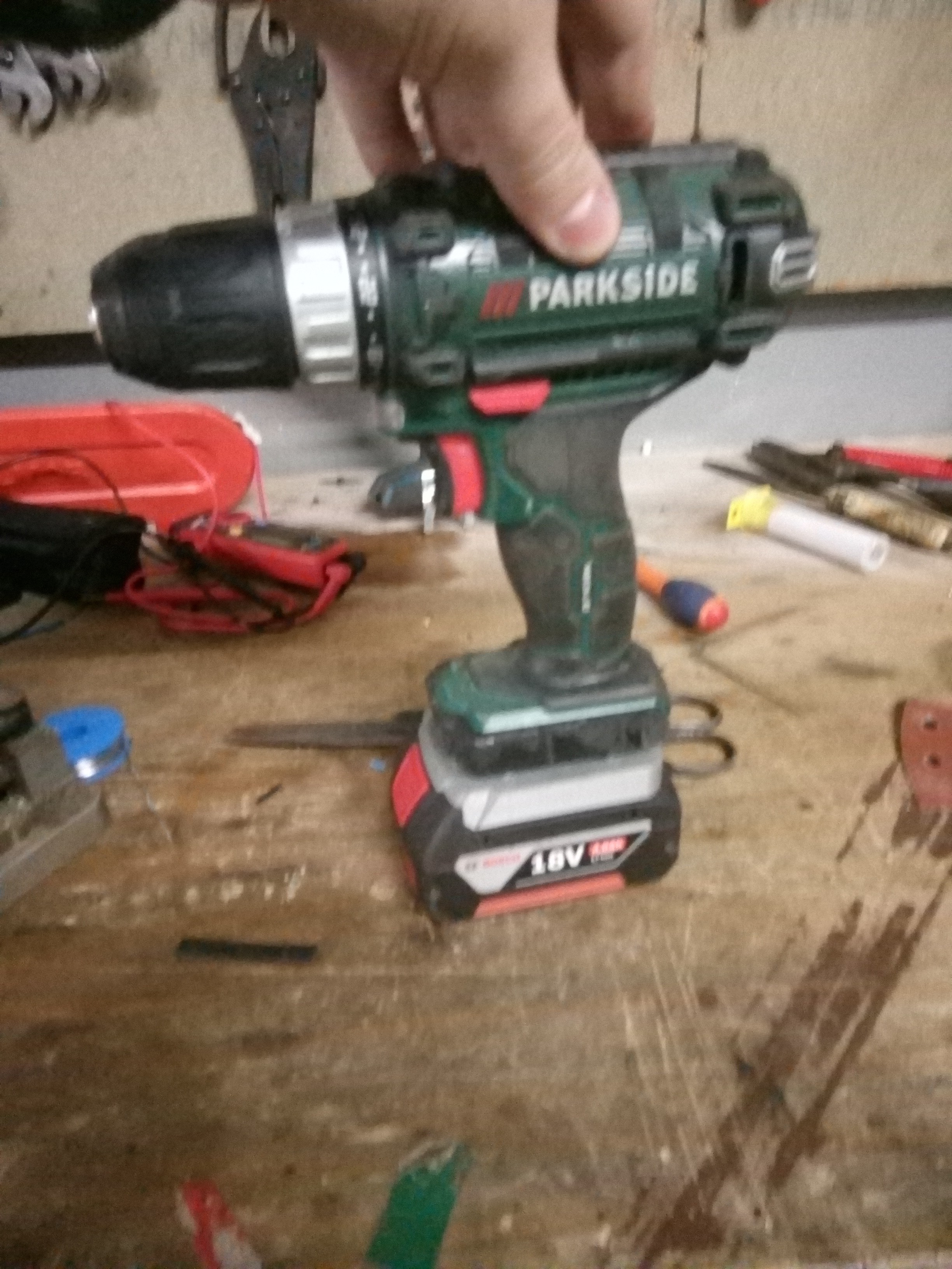
First test :
it's a WIN !
![]()
-
The Parkside side
01/28/2018 at 00:27 • 0 commentsIt's time to release your anger !
Open the old battery (I had screws). ACT WITH CARE : the battery, even weak, has some energy left and could arc with a watch, ring, bracelet ... and burn you.
![]()
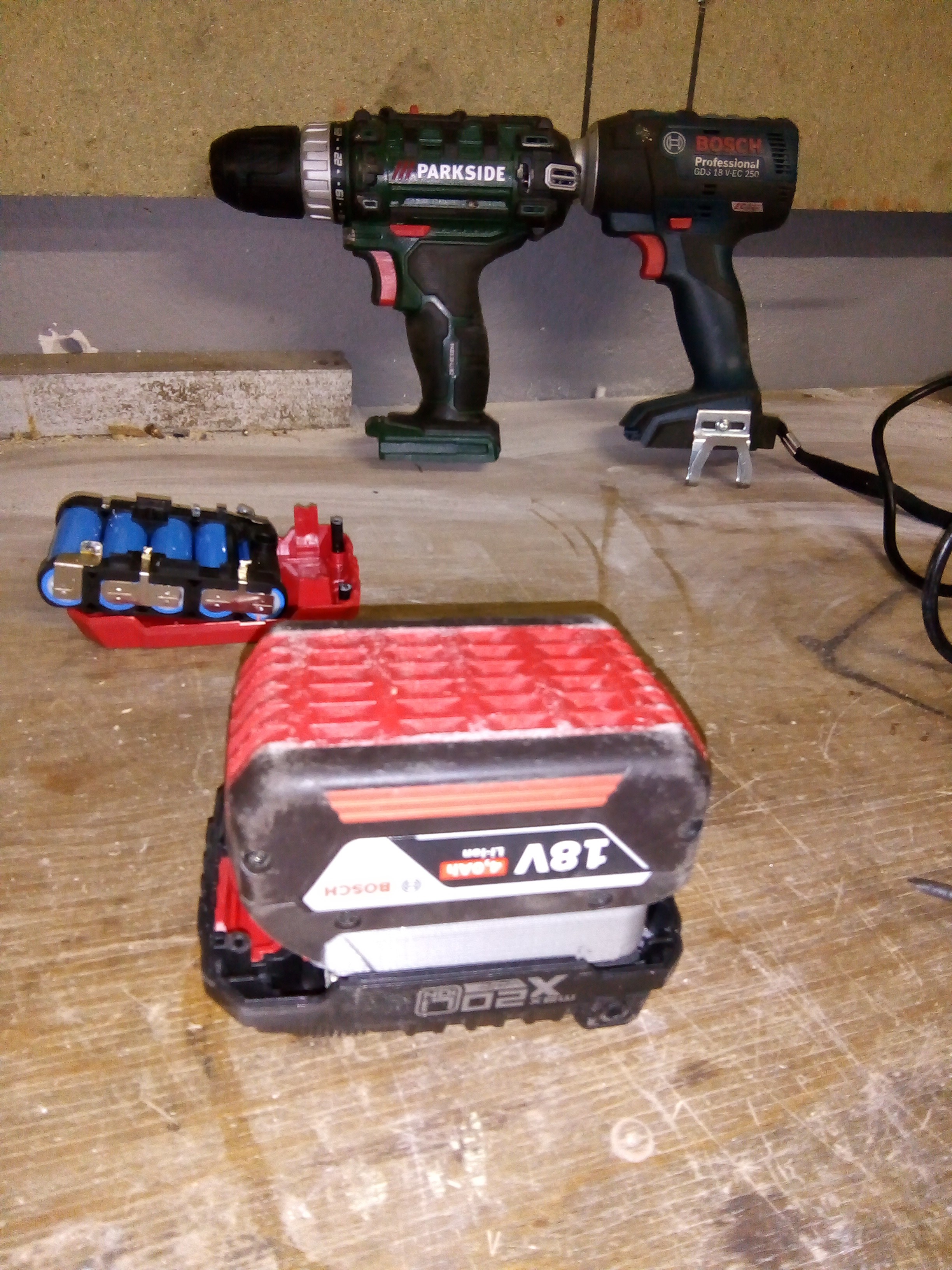
Fit test :
![]()
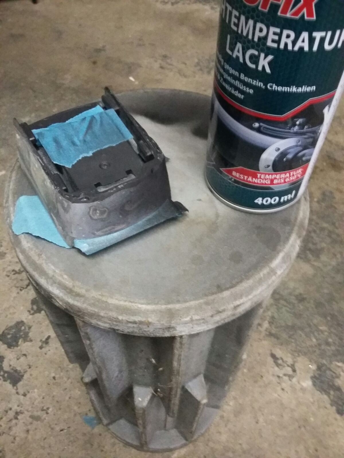
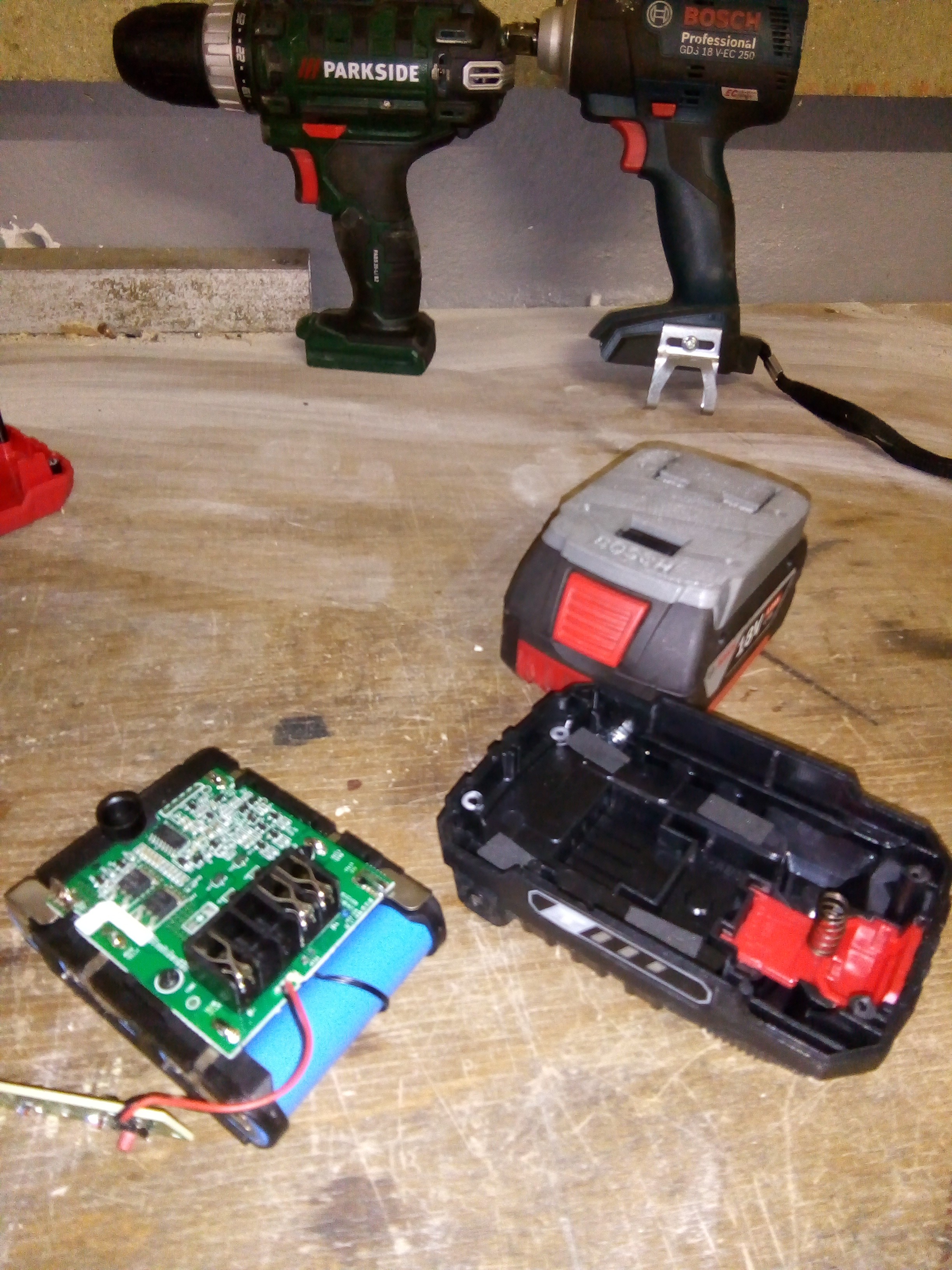
Hack it up! :
I cut the edges keeping the electrical connector interface.
![]()
![]() In my case the connector was soldered to the board (the black piece on the PCB), so I de-soldered the board from the cells and then de-soldered the connector from the board's underside :
In my case the connector was soldered to the board (the black piece on the PCB), so I de-soldered the board from the cells and then de-soldered the connector from the board's underside :![]()
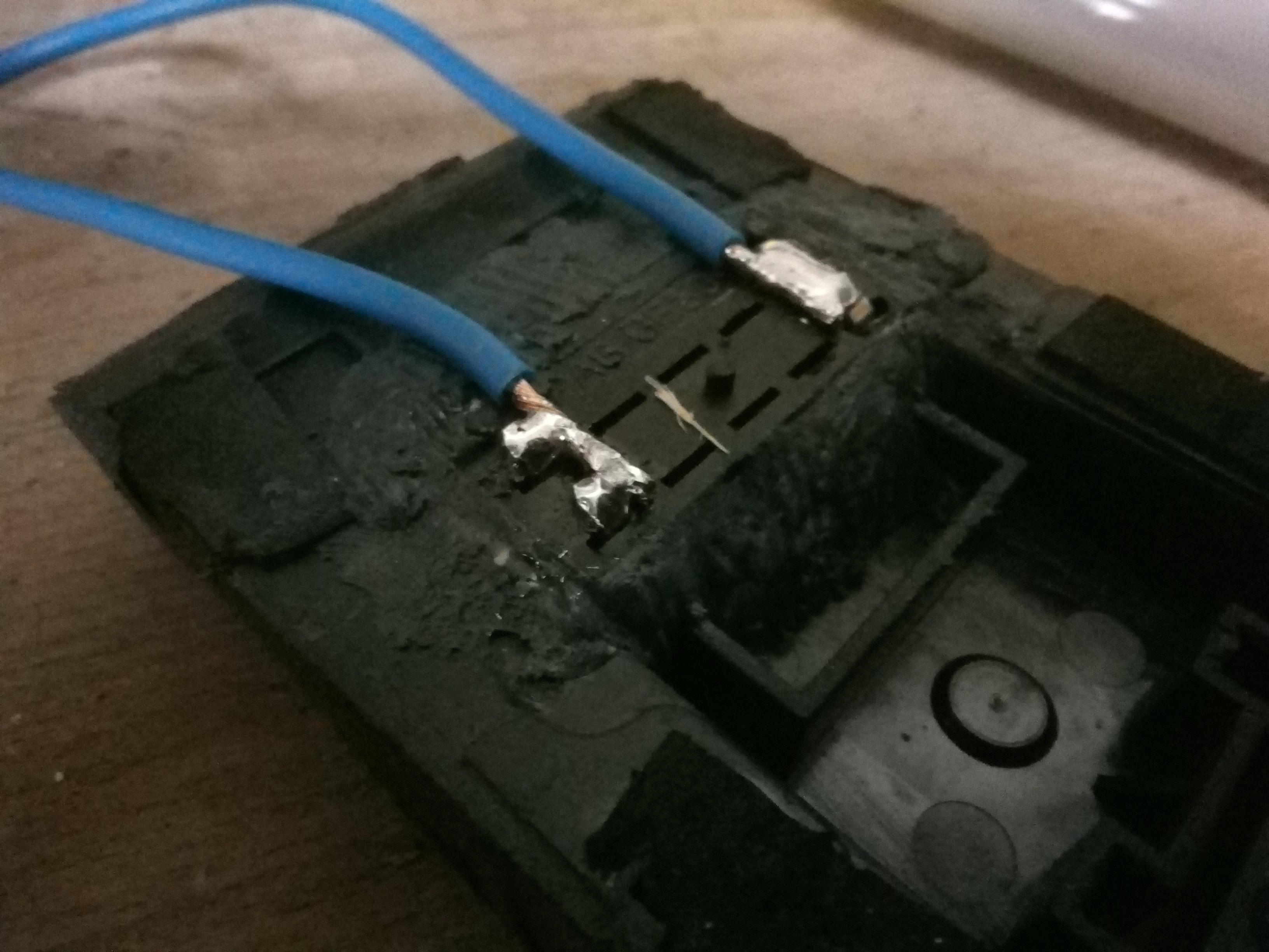
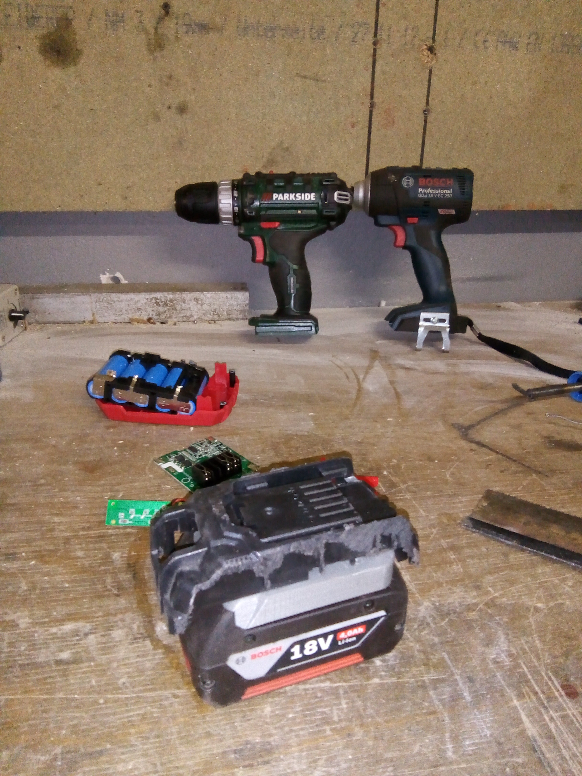
Glue the connector to the case and solder wires ;
![]()
We are done here ! Next comes the assembly.
-
The Bosch side
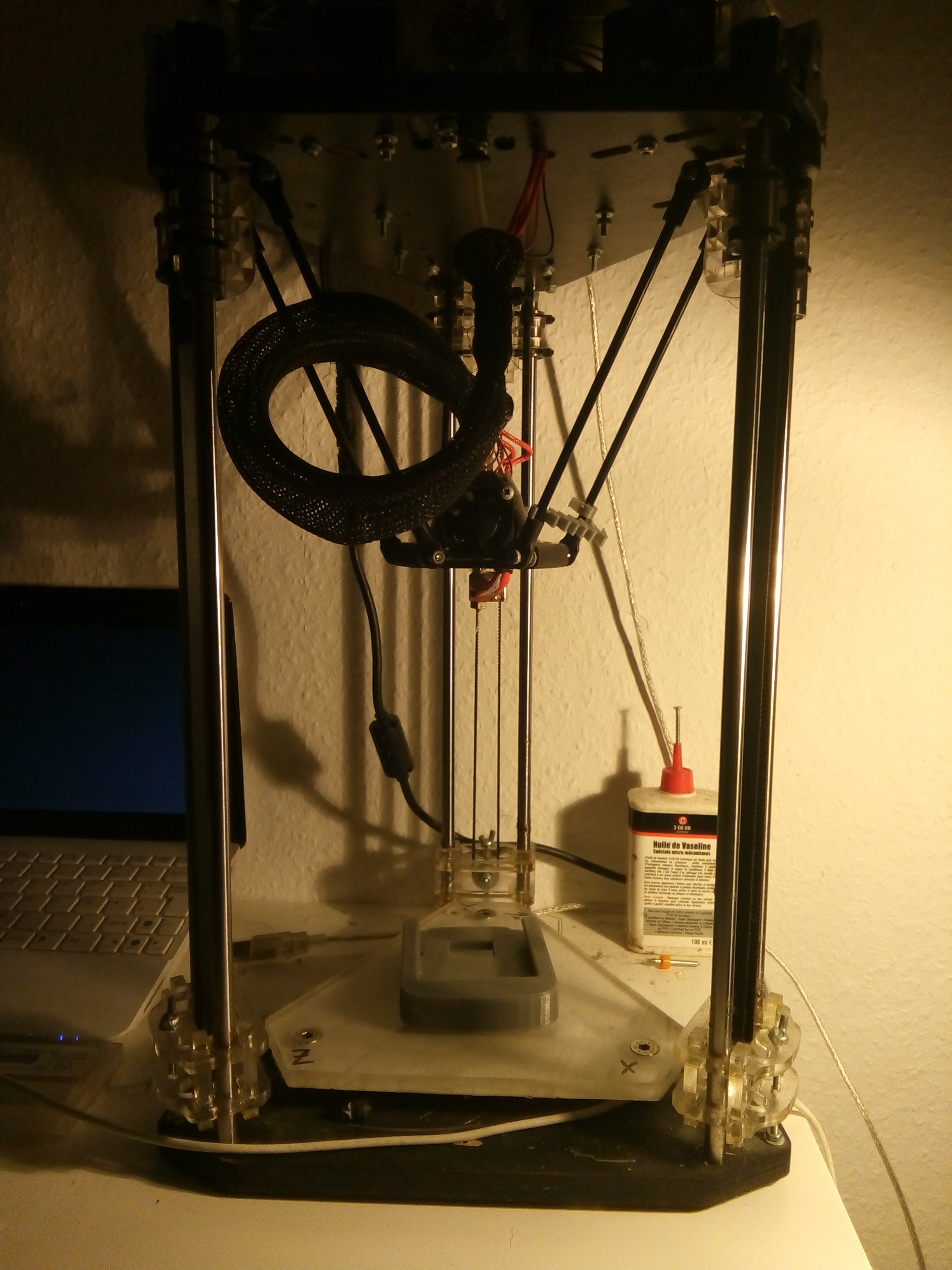
01/28/2018 at 00:01 • 0 commentsThanks to Simhopp : https://www.thingiverse.com/thing:1815758.
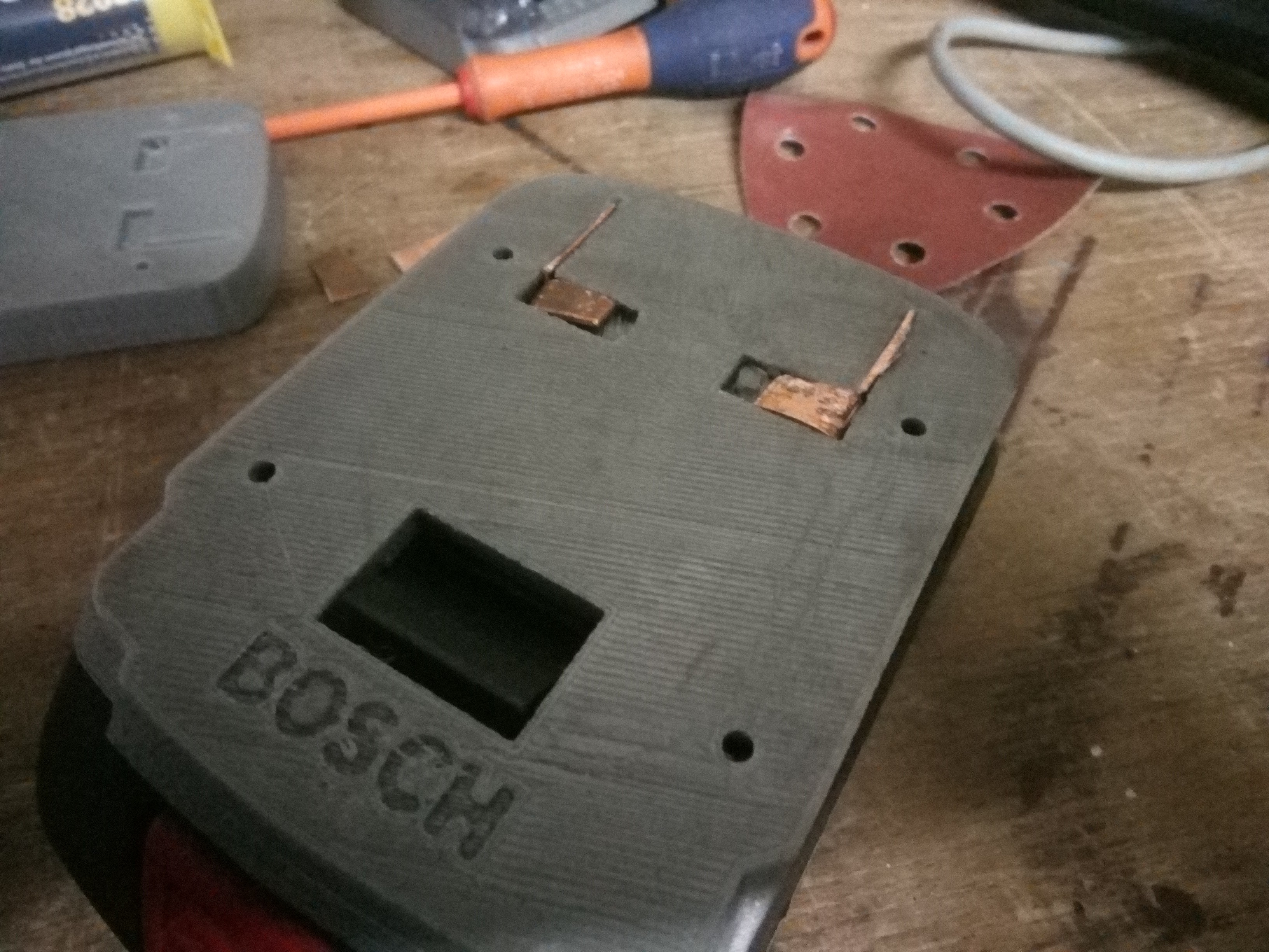
I printed the Bosch Pro 18v battery socket with my RepRap Emotion µDelta.
Printing parameters : 95% infill at 50mm/s, 0.2mm layer height and support.
![]()
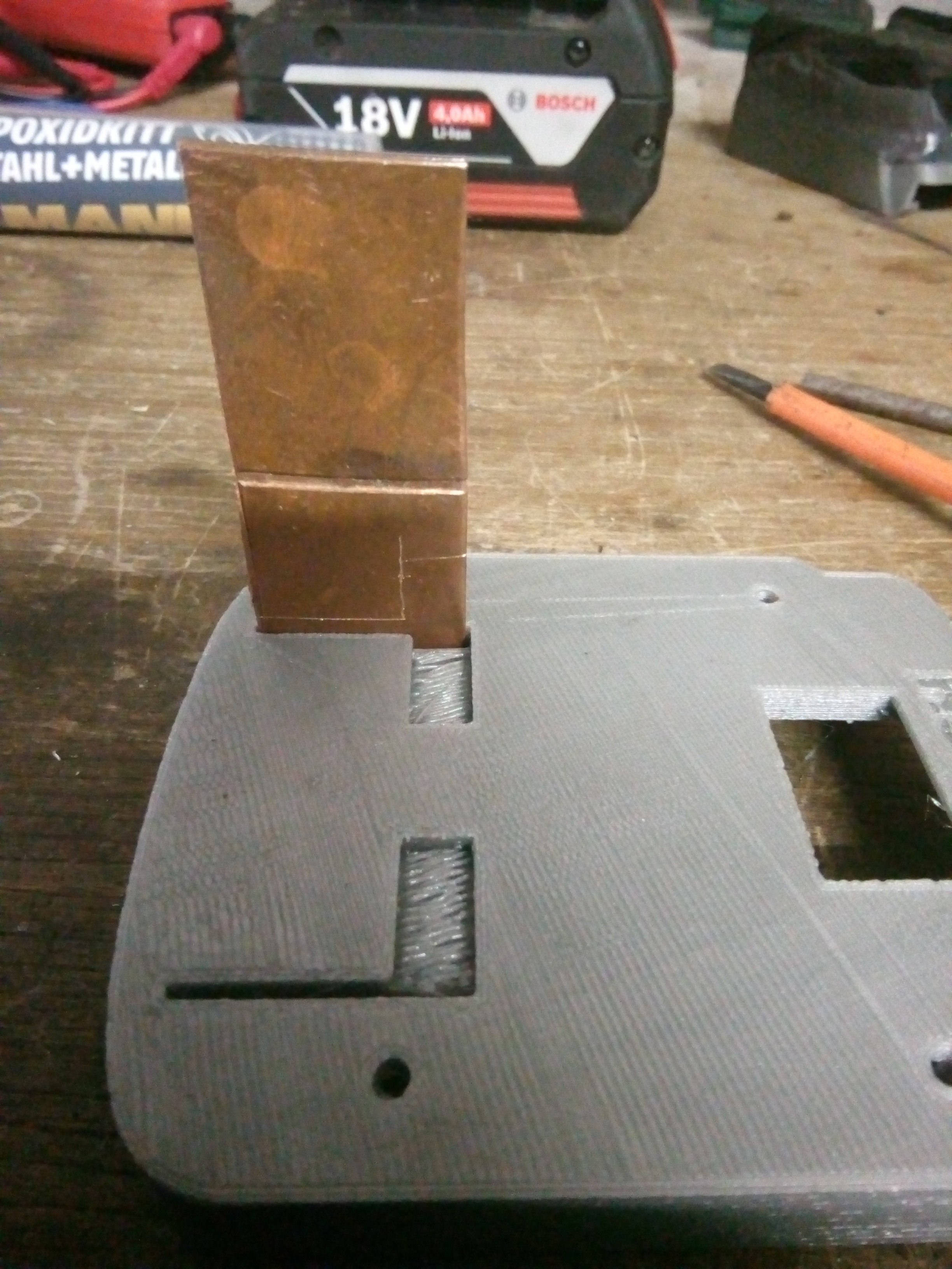
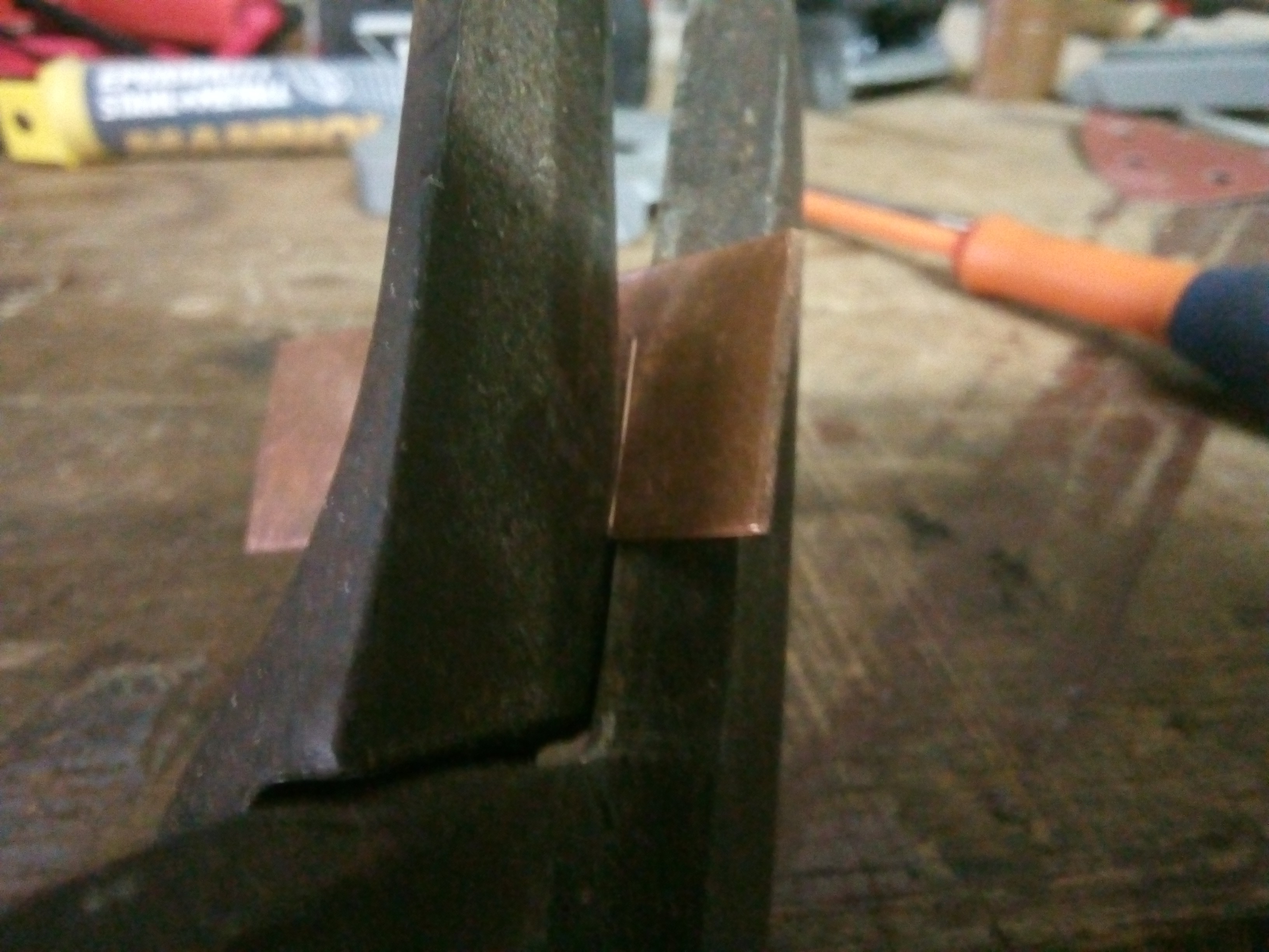
Then make the electrical connection :
The pads are made from a flattened copper plumbing tube with a thickness of 2mm. It will most certainly corrode so remember to later use electrical grease on the pads.
Cut a piece that will fit tightly in the gap then mark the piece with the line you need to cut :
![]()
Cut following the lines (hacksaw would also work) :
![]()
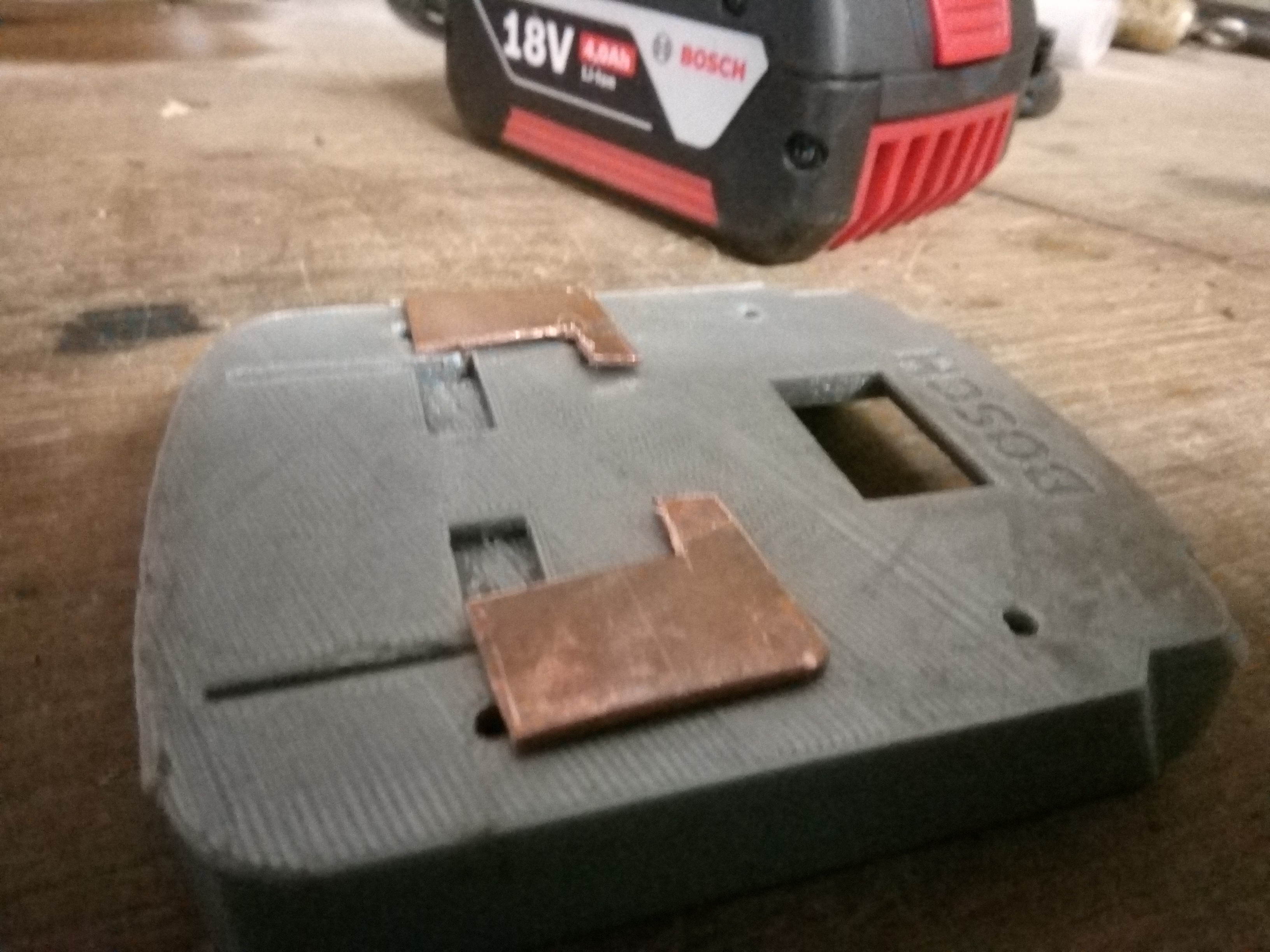
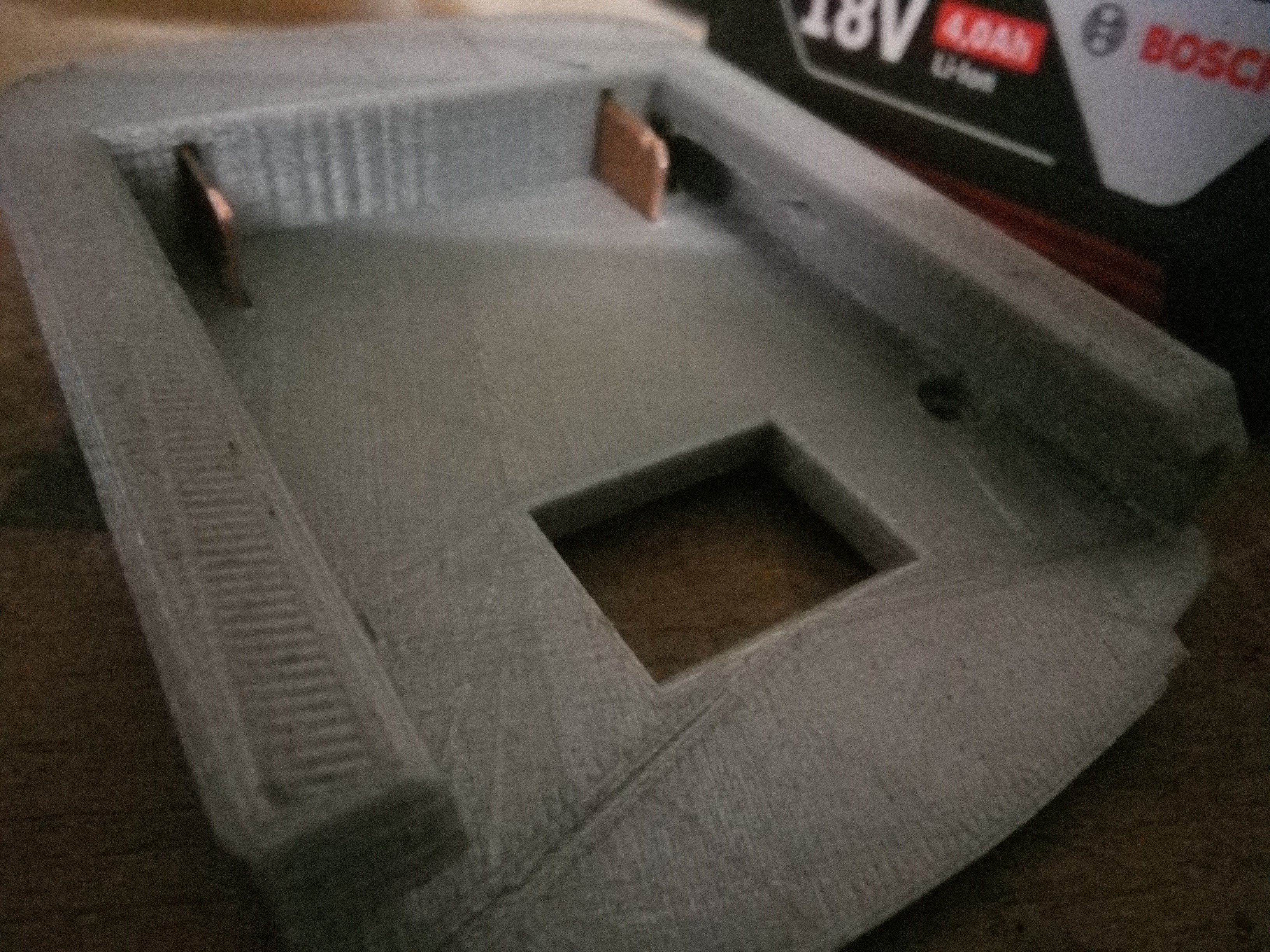
Install them in the groove :
![]()
![]()
![]()
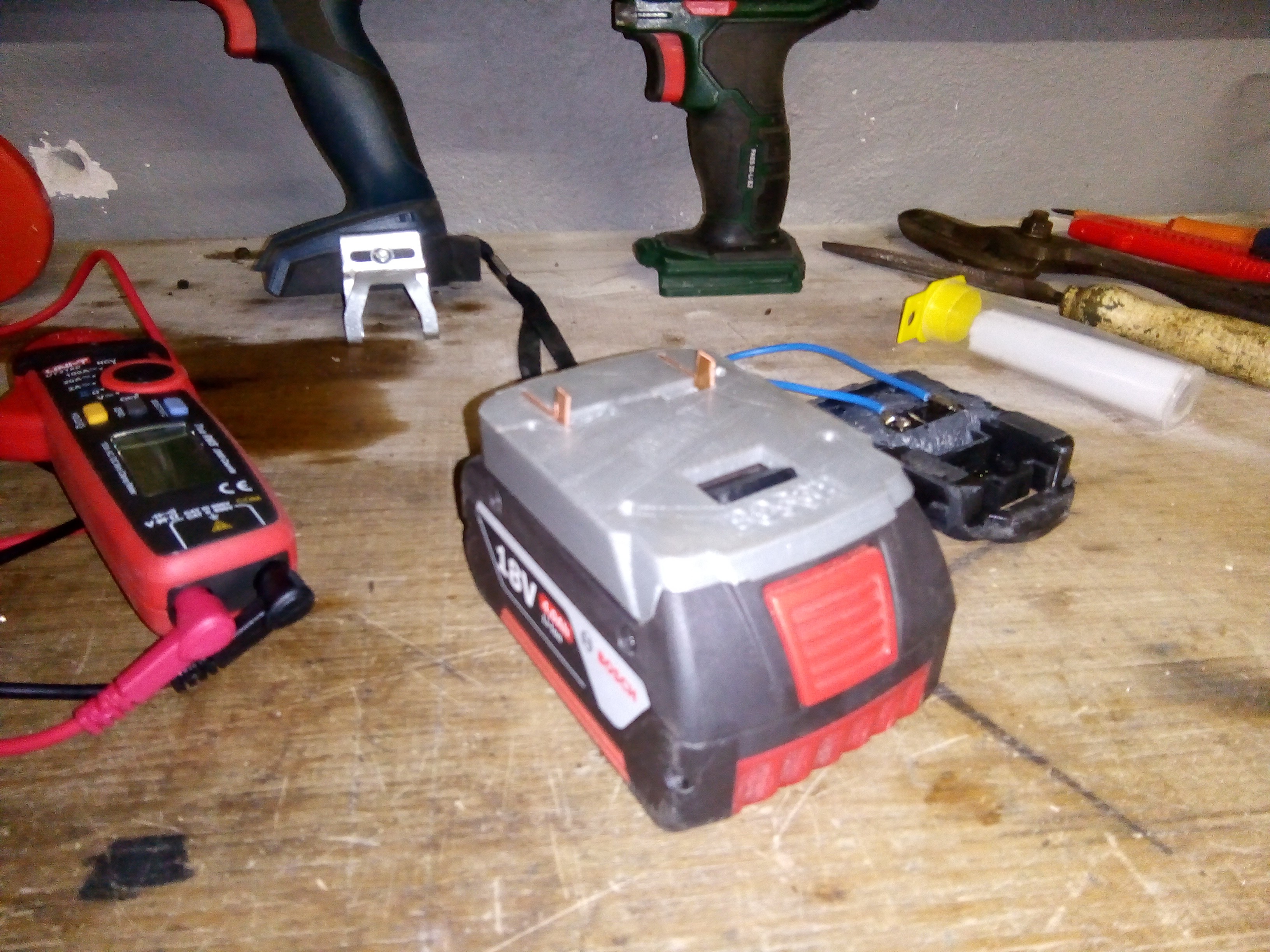
Test the voltage between connectors with a voltmeter :
![]()
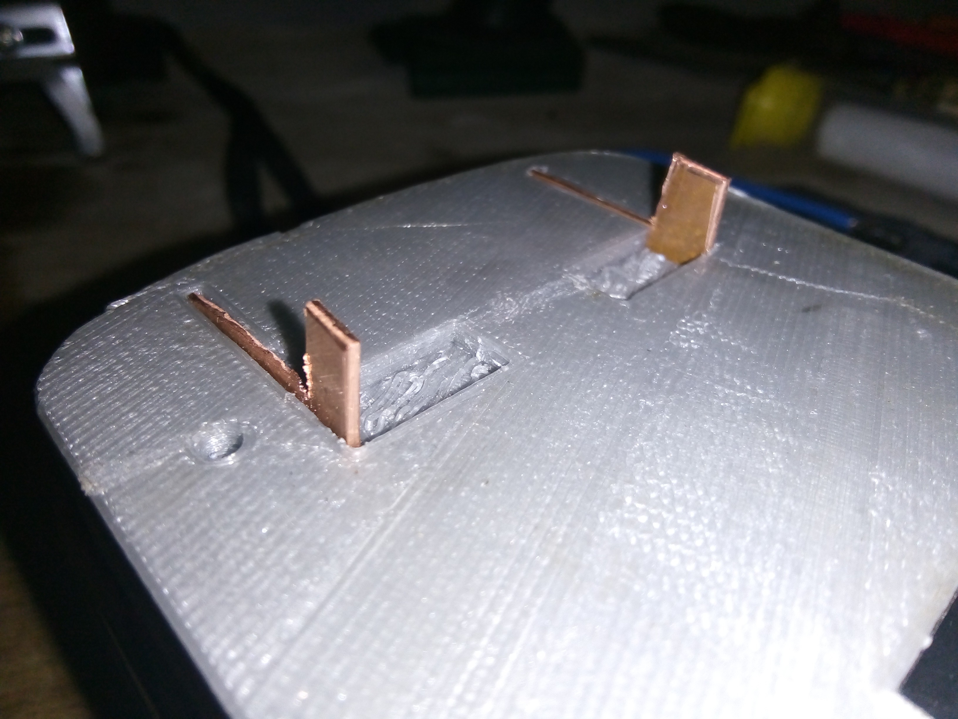
Bend the tabs flush :
![]()
Electrical connectors are in place, socket is ready for soldering.
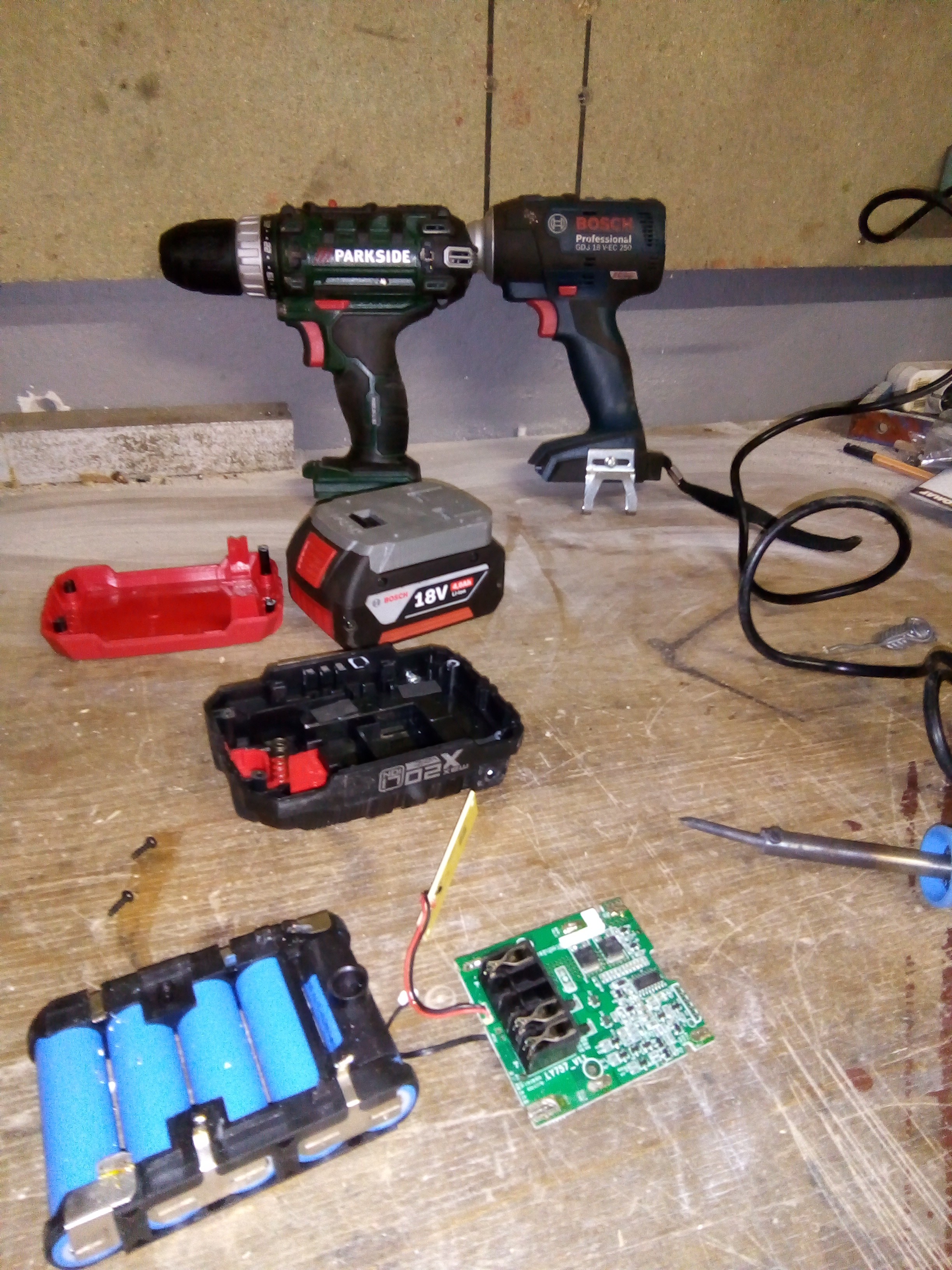
The Long Legged Drill
Mix-mash of an old battery case and and 3d printed part gued together to get a cheap Parkside Drill to serve again

 In my case the connector was soldered to the board (the black piece on the PCB), so I de-soldered the board from the cells and then de-soldered the connector from the board's underside :