Elia
Elia-
Rev. B PCBs have arrived
05/30/2015 at 14:54 • 0 commentsSorry for the long inactivity but I'm still very busy and the shipping of the PCBs took very long this time. After another 4 weeks of waiting I could finally pick up the PCBs from the post office yesterday evening.
I immediately started assembling and debugging the circuit. As of now the constant voltage part of the supply seems to be working fine after adjusting the software for the new output voltage range and fixing a mistake in the voltage adjustment circuitry.
The constant current adjustment needs some more fiddling with, I think the time constant of the LPF is too long for effective current limiting.
As you can see the new LM350 also has a small heat sink attached to aid in cooling the device. The LCD now has an LED back light driven by a constant current circuit.
The two TO-93 packages you see are 2N3904s that I bodged in instead of the SOT-23 2N2222A which I seem to have misplaced (they definitely show up on my distributor's invoice and I swear I had them somewhere 3 weeks ago :P).
I just wish I had shown my schematic to others before doing the layout and ordering new PCBs, maybe the would have caught a wrong feedback resistor in the voltage adjustment circuit.
So as you can see the project is still active it's just finding the time to keep it going is a bit hard currently.
Cheers,
Elia
-
Important changes (and why it's going slow at the moment)
04/30/2015 at 17:54 • 0 commentsIt's been almost two weeks since the last update so I thought I should give a quick overview of what has happened.
I have exchanged the LT3083 with the much cheaper LM350T. The original idea to using the LT3083 was that this regulator could be adjusted down to 0 volts without much effort. As it turns out for true 0V output even with the LT3083 I need to power my op amps from a negative rail to pull the SET pin sufficiently low.
After thinking about it a bit seeing that there was no way to get around implementing another DC-DC converter to invert the input voltage and generate a negative voltage for the op amps, I decided to change out the regulator because now the LT3083 was not really convenient any more but just an expensive LDO.
The negative supply is provided by the venerable MC34063 in an inverting configuration. I have also changed out some of the op amps. What's left are a LM324 for setting and regulating the current and voltage and a LM358 for the PWM buffers.
I have also thrown in an LM4040 2.5V voltage reference so I can have some confidence in my measurements and set point offset. I'm not sure why I originally skimped on that in revision A, probably I wanted to save a bit because of the expensive LDO.
I have started the layout but it is only slowly creeping forward because I am really busy with studying for university. After a whole day of studying, PCB layout isn't exactly what I define as a relaxing activity.
As always all the current development hardware and software files can be found on GitHub.
-
Revised design for better current limiting
04/18/2015 at 17:38 • 0 commentsI have revised the design again so that the current limiting doesn't tend to oscillate as badly as before. The current limiting is now done with a dedicated op amp that linearly controls the SET voltage of the LT3083 instead of just pulling it to ground like a comparator would. This is inspired by Dave Jones' uSupply.
The power supply itself works quite good after ironing out some bugs in the software debouncing routines and the rotary encoder decoding,
Some of the changes include:
- the LCD LED backlight is driven by a transistor based constant current source for higher efficiency
- the encoder outputs are now connected to the two external interrupt pins of the ATmega8
- fixed current limiting to work better and allow a proper constant current output mode
Also, I have slightly changed the specifications of the power supply. The LT3083 has a maximum input voltage of 18V, so I have changed the maximum output voltage of the supply to 15V so that the maximum input voltage to the LDO from the pre regulator is around 17V.
![]()
-
PCB (almost) fully assembled
04/11/2015 at 10:28 • 0 commentsComing back to Dresden after the Easter holidays I finally found the OSHpark PCBs in my mail box.
I now have the PCB almost fully assembled (I can't populate C10 because of clearance issues with the aluminium case) and now I am waiting for the 24V 3A power supply to arrive so that I can power up the board. The assembly has been a bit tricky at times because some components were very close together.
I have uploaded two images showing the Rev A board assembled and mounted on the case. Please excuse the somewhat crude soldering, this was my first time soldering after about 6 months without having even a basic lab setup. I also have to clean the boards with some isopropyl alcohol but I wanted to upload some images and give a quick update to show that the project is still alive ;)
-
Components ordered, firmware development
03/15/2015 at 16:27 • 0 commentsI have ordered all the other necessary components so I can assemble the board as soon as the PCBs arrive from OSHpark. After I had sent the PCBs off to OSHpark I had noticed that I had forgotten to put in the LM334 constant current sink but I quickly added that to the layout and contacted laen to change the gerbers, hence the rendering that you can currently see in the gallery for this project aren't completely correct as they're missing a chip.
The LM334 is needed because for stable operation the LT3083 needs a minimum load current of 1mA.
The firmware development has also progressed pretty far. The complete user interface and control code is implemented as a finite state machine. I am not sure whether I will employ software debouncing of the buttons too or if I rather just rely on the hardware debouncing circuitry I have added. The only thing missing from the control code now is just reading the button and encoder pin values and changing states in the state machine accordingly.
-
Revision A PCB layout completed
03/08/2015 at 17:35 • 0 commentsI have just completed the revision A board layout and ordered some PCBs from OSHpark.
I have made some more changes to the schematic during the layout phase which includes adding two more buttons for a much more user friendly UI. This means that I don't have to dick around with two buttons and a rotary encoder to switch between constant voltage and constant current modes or enabling/disabling the output. The rotary encoder will now purely function as a voltage/current setting device and the original two buttons are just for selecting which value (and digit) to change with the rotary encoder.
The final size of the PCB will be 105mm*64.4mm because that is the way the project enclosure I will use will be sized. This size allows all the components to be easily placed while also leaving enough room for banana jacks and a 16x2 character LCD. The banana jacks are spaced 3/4" apart as is usual with power supply binding posts.
Now that I am waiting for the PCBs to be manufactured and the boards to arrive here in Dresden I will start with the firmware for the power supply.
-
Changed the pre-regulator, first schematic rev done
02/27/2015 at 21:26 • 0 commentsIt seems that I have completed the first revision of the schematic and I will be doing the layout throughout the next week. I still have one last final this semester so the time I can spend every day on the layout is somewhat limited.
I have decided to change the tracking pre-regulator to a Texas Instruments TPS54331, which is a 3A continuous output current switching regulator. I have decided to do this mainly because it has a much smaller footprint (SO-8 with thermal pad) instead of a big TO-220 package. In my previous update I had mentioned that it was hard for me to source components because here in Germany Farnell/Element 14 won't sell to non-businesses and DigiKey is not an option due to shipping cost and customs fees. An added bonus is that I can use TI's WEBENCH software to calculate the component values for the output filter and compensation network.
I got these devices through TI's sample service as I am an EE student at TU Dresden. The sample package arrived here within 3 business days.
I am still not 100% sure that this will work the way I want it to but I figure it's worth just giving it a shot.
-
Changing the linear stage
02/23/2015 at 21:23 • 0 commentsI have been talking to some people who are much smarter than me when it comes to analog circuit design and we have come to the conclusion that it might be a safer route to go with a ready made LDO, ideally something like an LT3083. The LT3083 is a 3A regulator that allows the output to be adjusted right down to 0V. Chosing a ready made LDO also makes it much easier to get the circuit to be stable over the full output current range and I don't have to spend ages trying to stabilize the MOSFET circuit.
I am still not sure as how to choose the inductor and output capacitor values for the LM2576 in my situation. There is an example in the datasheet of a 1.2V-55V 3A adjustable output voltage supply but the values that I get using the recommended component selection procedure in the datasheet just don't seem to match up with the values they indicate in their example circuit.
Unfortunately as a student/hobbyist I am a bit limited in component selection here in Germany. There is a very promising switchmode regulator by TI the TPS4331 which seems to be a more modern version that operates at a higher switching frequency which helps reduce the physical indcutor size. If I was able to use that I could save board space and probably have a slightly more efficient tracking pre regulator.
Asking over on the EEVblog forum about this issue didn't get me any useful replies so I might have to change the pre-regulator.
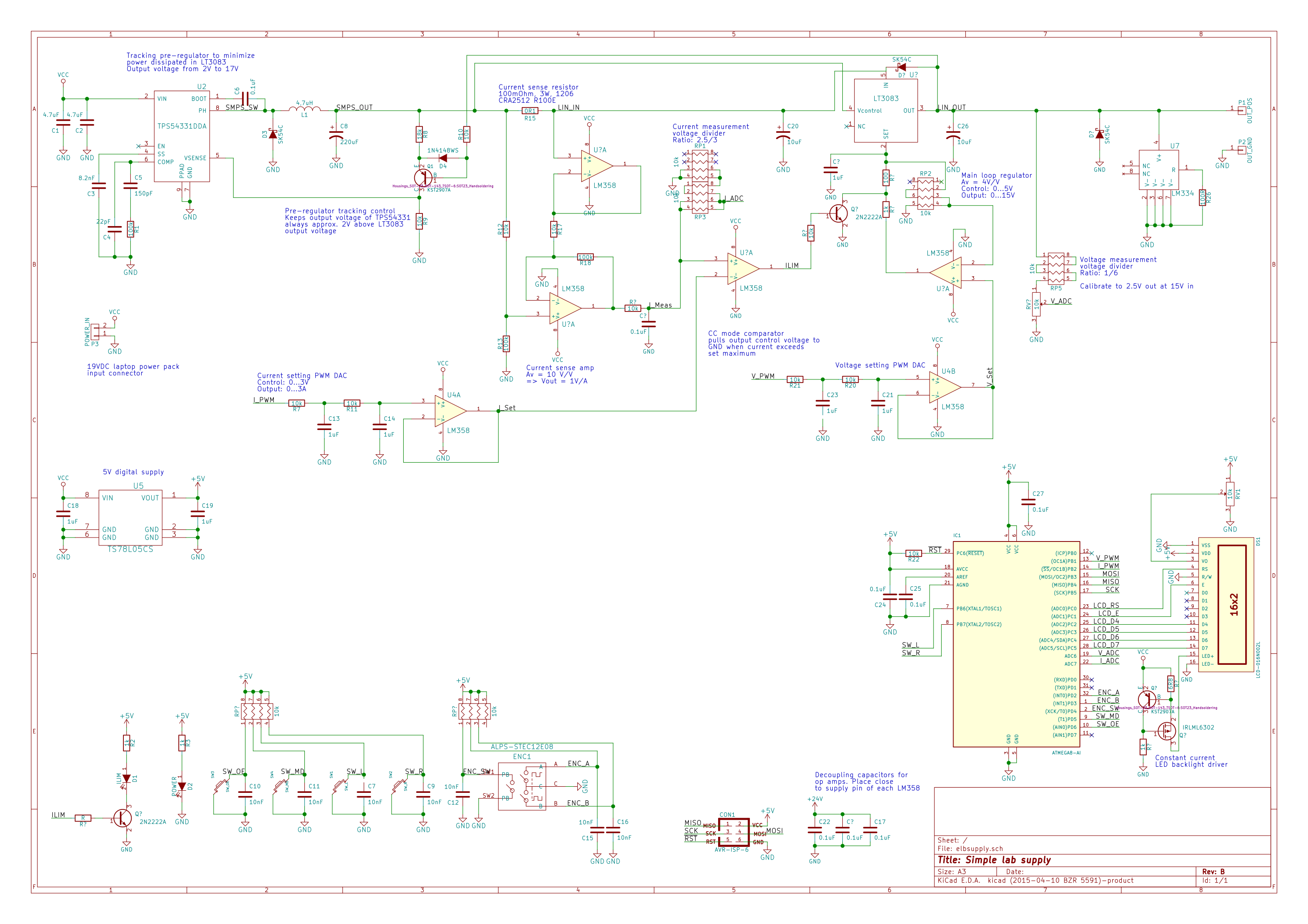
ElbSupply - Simple linear bench supply
This project aims at building a rather simple yet useful bench power supply for everyday tinkering.