John Taylor
-
Iracing Demo
03/24/2019 at 17:16 • 0 commentsDemo In IRacing with a few different cars
-
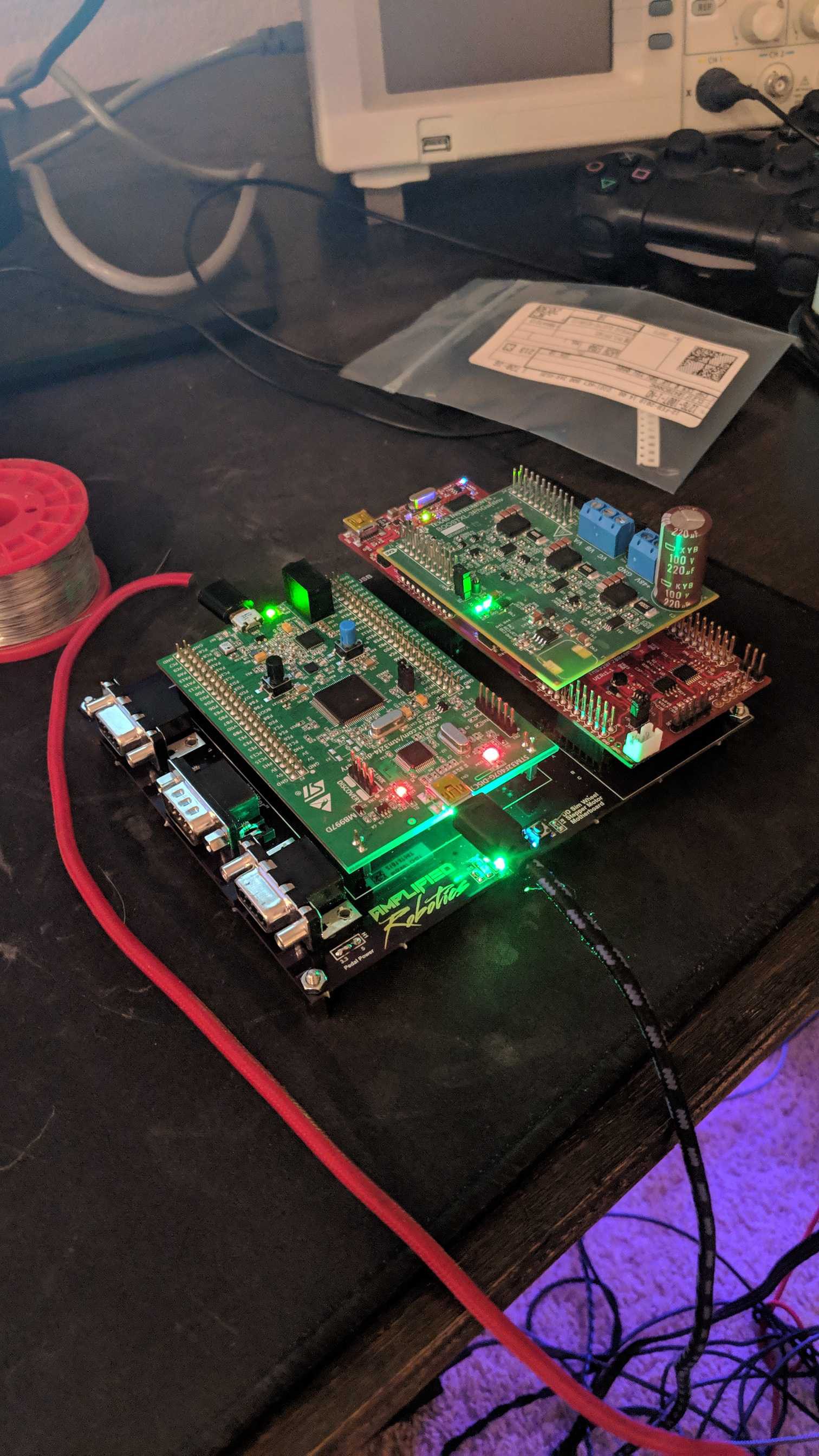
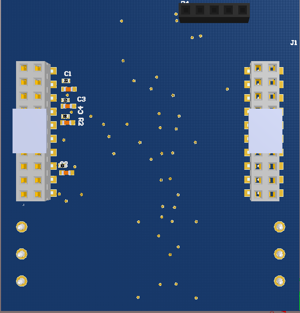
Received MOBO from fab
02/24/2019 at 05:05 • 0 commentsI received and partially assembled the new DD stepper motherboard from @oshpark today. So far so good. All of the pins for stacking the STM and C2000 dev boards line up perfectly. I was able to connect to MMOS after some fiddling and was also able to connect my G27 pedals and shifter and get them working...well mostly. The shifter is having issues shifting into reverse, but I'm confident that I'll be able to figure that out in the next few days.
Unfortunately I forgot to order a few components, namely a level shifter and a DB9 connector to attach to my encoder. I have these parts on order and should receive them in the next week or so and then I'll be able to test the wheel input. Also the huge inductor on my motor driver board broke off and took the pads with it. I'm going to get in touch with TI and see if I can get a replacement because that board is pretty expensive.
Overall it came out looking better than I expected, and I'm excited to get it working fully.
![]()
-
Success!
02/21/2019 at 17:45 • 0 commentsI am happy to announce that @matthew.gregg has taken the skeleton of the platform I have been developing and massaged it enough to get it working with Assetto Corsa! Using the STM Disco board and MMoS game controller integrated with my FOC software for stepper motors Matt is shown below making some laps with his good looking DD wheel.
I have to give Matt a lot of credit, he took a lot of his own time to work on this project, even when I hadn't touched it for months. He has also provided invaluable information for the design of the system.
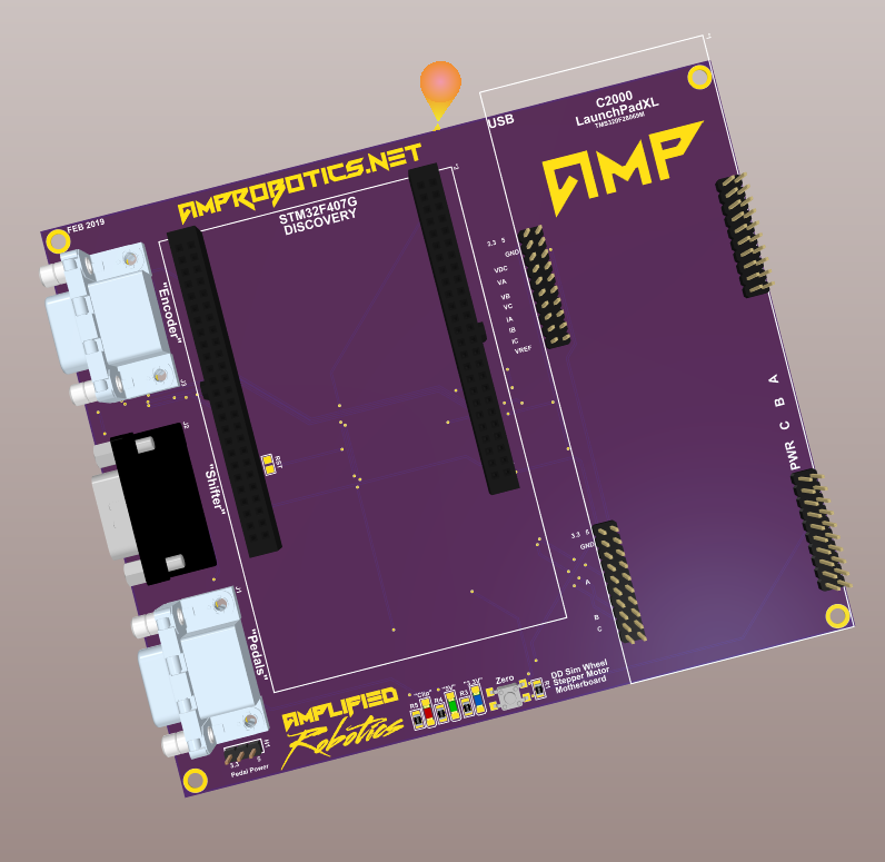
Matt has also inspired me to finish the latest PCB design for the project, which is a motherboard to integrate all of the motor control components as well as add connection for the G27 shifter and Pedals. I should receive the prototype for the motherboard in a couple days so that I can begin testing. For now, here is a sneak peek at the MOBO. If it ends up working, I'd like to make it available to fellow DIYers! BTW the website on the board is under construction and not available yet.
![]()
-
The Grand Redesign
11/07/2018 at 04:27 • 0 commentsHi Folks. I left you guys last time with news that electrical noise from the motor was causing problems with some of the important signals in the design. The PWM signal from the PC that lets the motor know how much force to produce and in which direction was so distorted that is was unusable and the encoder signals were affected at high currents. I ordered a new motor driver with integrated phase current sensing to move the motor traces far away from the signal traces on my board, but when It arrived, it did not fit on the current C2000 launchpad with my custom driver board well at all. When I did get it to fit, I had to re-do the encoder connection and ended up breaking one of the pins off of the back of my US digital encoder... This was the second pin that broke on this encoder and It took some real finesse to re-attach the previous one.
Instead of trying to patch the encoder up and continue testing, I took this as an opportunity to address some of the major design flaws with the project.
First, the encoder is a pain to install. It requires a custom 3D printed adapter, Standoffs and also requires gluing to the motor shaft, which at best is tedious and at worst causes misalignment that could rip the connection apart at high speeds. Also I was using a single ended encoder, which is susceptible to noise compared to a differential encoder. To remedy this I searched and searched for a through-shaft encoder to easily attach to this dual shaft stepper motor. After several hours of searching for a through shaft encoder with a 12mm hole with no luck, I was just about ready to give up. Then I had one final idea...Check Alibaba. Immediately I was presented with several serviceable solutions and settled upon the GHH60-12G5000BKL5(60mm outer, 12mm through hollow shaft, 5000PPR, 5v line driver output, 1 meter cable side) encoder from CALT. I should be receiving the motor and encoder by next Monday, so We I'll be interested in the quality of the encoder and to see how well the motor and encoder fit together. Hopefully this will solve the encoder noise and fitment problems for good.
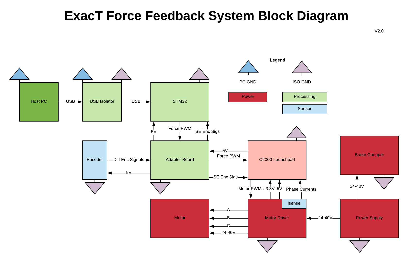
Another problem was the entire interface to the STM board. I was trying to isolate all of the signals from the board, but the power for the board and the USB comms were two separate connectors so there were a lot of wires everywhere on my desk. To simplify this, i will power the STM from the motor supply and isolate between the computer and the STM USB comms. This will require a custom adapter board that will connect the motor driver, C2000 board and the STM. It will also contain the differential signal receiver for the encoder. Here is a block diagram of what the new system will look like.
![]()
I hope to be getting into some of the PCB design soon, but I have been doing a lot of that at work lately so it's hard to find time/motivation. Should have something by the end of the year.
-
MAKE SOME NOISE
10/23/2018 at 02:18 • 0 commentsAlthough it has been several months since I updated the site, I have still been working on the project. Since the last update I have met several milestones, and ran into a HUGE hurdle. Let's get into it.
The biggest accomplishment I have made so far has been getting motor current control working. I was able to leverage TI's IQmath fixed point library to implement the Field Oriented Control algorithm so that it runs fast enough to be useful. It was a challenge to get all of the libraries working and I have to remove all of the function calls from the algorithm to make it lightning fast. With all said and done, the algorithm works well.
I have noticed that sometimes the measured electrical phase angle becomes offset from the actual value, usually when the motor is under heavy load. I am chocking this up to noise from the motor interfering with the encoder signals.
I have also been able to get the PWM capture from the STM disco board working. The PWM from the disco board tells the motor controller how much force to apply and in which direction. Unfortunately when the motor is running the signal is severely distorted. This seems to be due to the motor power trace running right next to the signal line. The noise on this line makes it impossible to do any real testing with IRacing, which is disappointing.
In order to solve these problems I have ordered a new motor driver from TI that will allow me to move the motor traces away from my signal lines.
I have also designed a "brake chopper" board that connects to to the power supply and prevents the motor from putting unwanted back-emf onto the supply.
-
Plotting
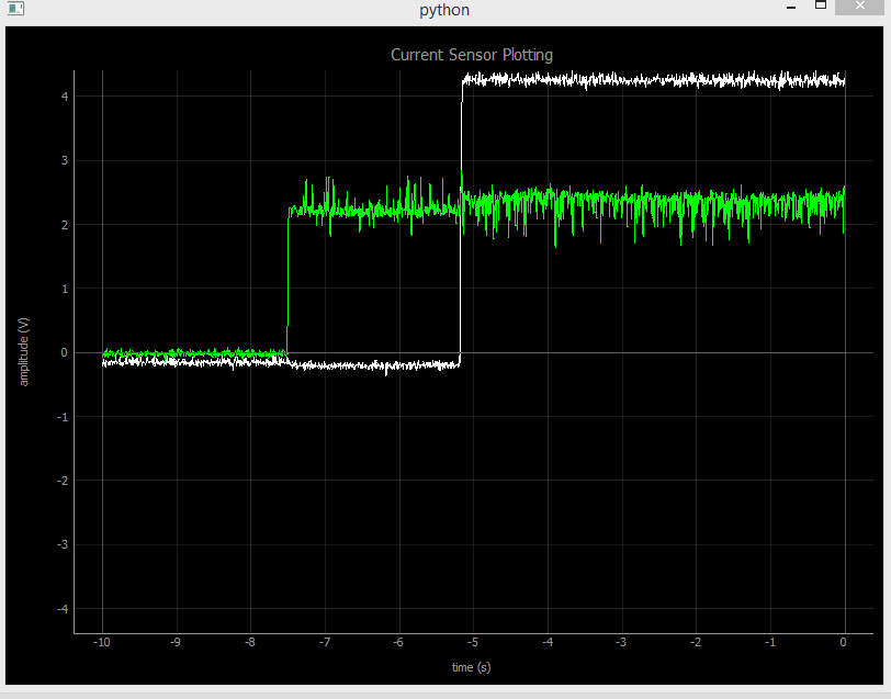
05/04/2018 at 02:09 • 0 commentsToday I finally got back to the project a little bit. I got the basic plotting functionality for the phase currents implemented and it looks pretty good. Hopefully later this week I can make the plots a little nicer and add labels, then start working on getting the controller math worked out and tuning. The github for the python plotting libraries can be found here : https://github.com/Taylorjtt/ExacTune
![]()
-
Testing complete...on to firmware development
04/06/2018 at 22:31 • 0 commentsUpdate
Wow, it's been a while since this project has gotten an update. After a long hiatus, I have finally completed the assembly and testing of the current sensing booster-pack. The only problem i ran into was one of the tiny 0402 caps was shorted because of a poor soldering job. I was able to fix that easily enough, and since I tested for continuity between power and ground before actually powering the board I didn't break anything. I also modified the firmware to use the new ADC channels that the booster pack feeds into. To verify, I was able to apply voltages to each of the motor phases and see the correct current output in the ADC registers. Over the last couple of days I have been working on a task-scheduler that I can use to do various tasks at fixed rates using one timer. I used this blog post as a template, but since I am using C++ I am doing things a little differently. Check the github if you are interested. I will use this for my control loops as well as data transfer to a host-PC (more on that later...)
Whats Next?
The obvious next step is to start working on the controller. We very obviously need current controllers for both the A and B phases. In my experience developing control systems, ones job becomes much easier if he/she is able to see an output of the control signals as well as the setpoint in order to do step-response test, see errors in real time, etc. My plan is to develop a GUI in Python that communicates with the motor control processor to facilitate this. This GUI will make tuning and validating the system much easier. I usually use Java for this sort of thing, so I am excited to see what Python brings to the table. Once the GUI is working I'll implement the PID controllers for the current control system and start testing.
-
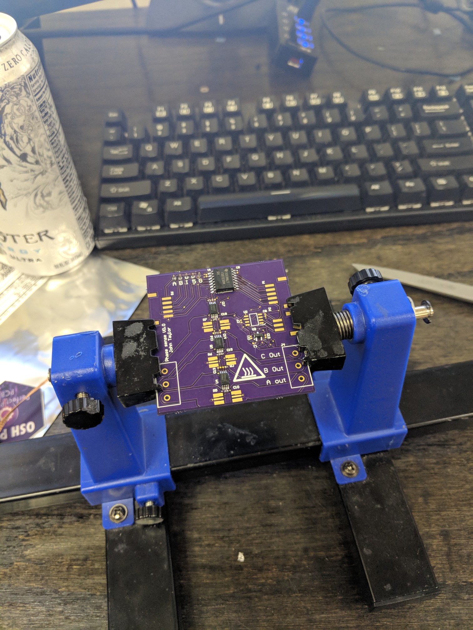
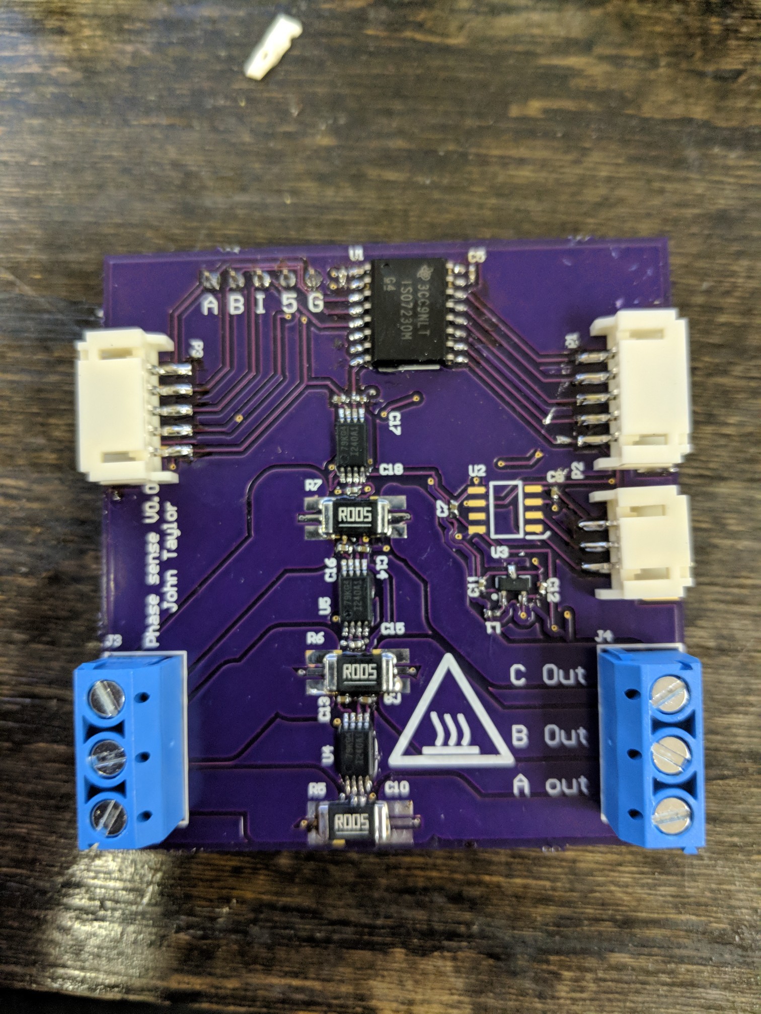
Current Sensing board 99% assembled + Test Plan
02/28/2018 at 19:52 • 0 commentsI received the phase current sensing PCB from OSHPark on Monday. I finally got around to assembling it today. Here are some pics.
![]()
![]()
![]()
If you look closely, you will notice that U2, one of the isolators, is missing. Unfortunately I forgot to order this part from digikey and I'll have to wait for it to come in. There were a few problems with the board. I used really tiny 0402 resistors and capacitors and from an assembly perspective this made things tedious. I also forgot to put a package outline and a pin-1 callout on the current sense amps so I had to reference the Altium file to figure out which way they needed to go on the board.
Test Plan
- Make sure no power nets are shorted to ground (done)
- power board on (done)
- Check Vref (done)
- Apply i known current through the channels and make sure it shows up on the output of the op amp (done)
- Check all of the digital signals to make sure they are working (done)
I probably wont get to this until late next week because I'm going to be out of town.
-
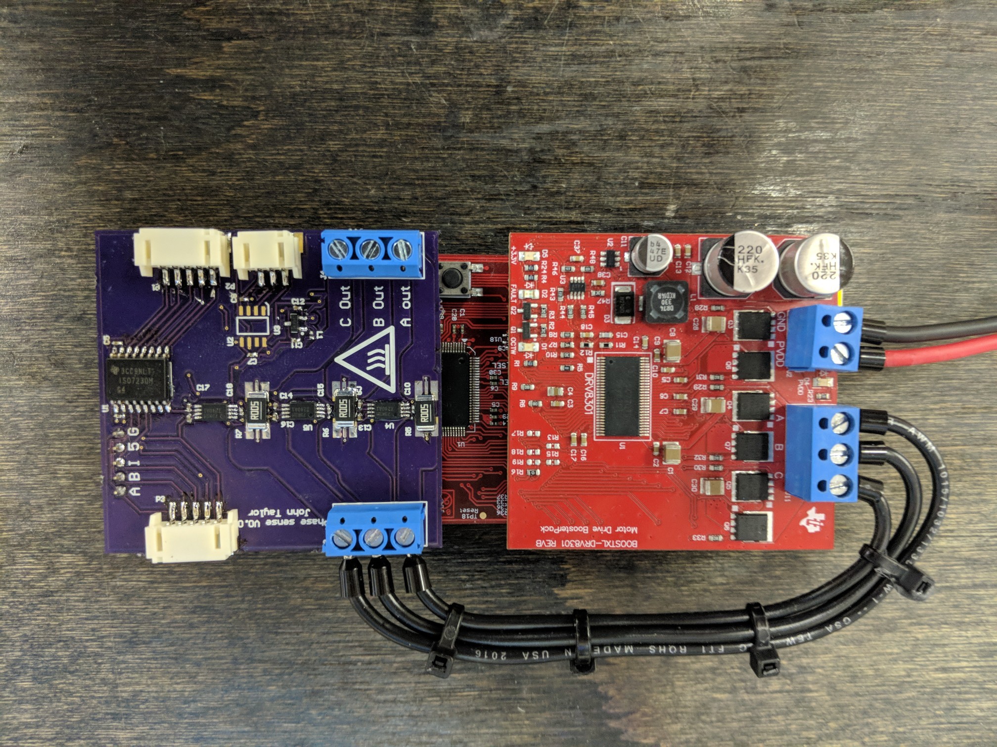
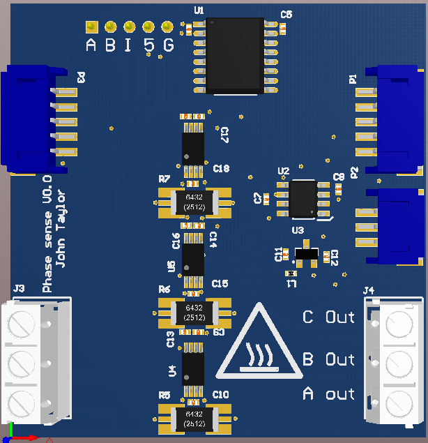
Current Sensing PCB is ordered
02/11/2018 at 21:44 • 0 commentsAfter a few weeks of tinkering, I finally finished the PCB that will allow me to sense the phase currents of the stepper motor. The phase output wires of the motor driver board plug into one side and feed the motor current through 5mohm resistors. Special kelvin connections that I learned about from this article were used to improve the measurement accuracy at high-currents. INA240 current sensing amplifiers from TI were used for their enhanced PWM rejection. With these components I should be able to sense currents from -16.5-16.5A. Isolators were added to isolate the motor driver processor/power circuitry from the STM discovery board. I have also added connector ports to route the encoder and PWM signals to the STM discovery board. This board has a standard booster pack layout and will plug directly into the C2000 launchpad.
![]()
![]()
-
Update
02/08/2018 at 04:39 • 0 commentsI have been working on the project for almost a month now and have accomplished a bunch, and also ran into a few problems.
Accomplishments
- Sourced motor, encoder, motor driver,wheel rim, game controller interface board (STM32) and motor controller processorboard (TI C2000)
- Mounted the encoder to the back of the motor with a 3D printed adapter. I had to machine a hole in the back of the motor case in order to have access to the shaft. I then drilled and tapped mounting holes and mated the encoder shaft with the motor shaft via an adapter. (pics)
- Mounted the wheel rim to the motor output shaft with a 3D printed coupler (pics)
- Wrote software to set up the Motor Controller Processor to talk to the Motor Driver/send PWMs and wrote a basic stepper motor algorithm to spin the motor up to about 300RPM
- Researched Field Oriented Control for Stepper motors extensively and made an excel spreadsheet detailing and graphing the desired current in each of the motor coils in one electrical cycle. (Great PPT on the subject)
- Got MMos set up on my STM32 dev board and got my FFB-less wheel to control a car in IRacing. (video)
I have however ran into one big challenge. The DRV8301 Motor Driver Booster pack from TI uses low-side current sensing. Because of the topology of the motor I am using, the sensors on the low-side of the inverter do not provide enough information to determine the phase currents. For this reason I have been working on a custom phase-current sensing booster pack that the motor leads will pass through on their way to the motor. This booster pack will plug directly into the launchpad dev board and provide the phase current information that I need for FOC.
The plan moving forward is to order the PCB in the next couple of days. As soon as i receive the PCB's I will test them and begin writing the FFB code.
SmoothStep force feedback steering wheel
The SmoothStep is an affordable precision force feedback sim racing wheel platform with open source hardware/software.