 Glenn Powers
-
1Step 1
![]()
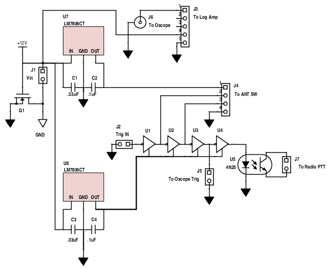
Here is the schematic for the power and trigger control board. You can view it in Scheme-It. Q1 is a N-Channel MOSFET to protect against an inverted polarity power supply. I used a LM7806 and a LM7808 instead of a single LM7505 to give a faster switching time. U1..U4 is a 7 channel hex inverter. J6 is a BNC connector. J3 should be a female header, others are male.
Open Ground Penetrating Radar
Make the invisible visible for about $500.
Discussions
Become a Hackaday.io Member
Create an account to leave a comment. Already have an account? Log In.
Hello, I wanted to design and build an FMCW ground penetrating radar. I would be grateful if you could share with me the challenges you faced in this project.
Are you sure? yes | no
Hi, I need also the files of this gpr project for my school graduation project. Please, would you be so kind as to send me the files of this project?. Thank you very much to those who are interested. fmorales_htw@hotmail.com - Francisco
Are you sure? yes | no
hello, I need the files of this gpr project for my school graduation project. Could you please send me the files of this project. Thank you very much to those who are interested.
eakar74@gmail.com
Are you sure? yes | no
hola, estoy interesado en el proyecto, puedes mandarme más info? Muchas gracias
Are you sure? yes | no
It seems to be a very interesting proyect. Could you give more info ?
thanks in advance
Are you sure? yes | no
voidmapper.com is unavailable.????
Are you sure? yes | no
and the rest of schematics? and de conections? this not help :-(
Are you sure? yes | no
I think it too. Please
Are you sure? yes | no
Hello,
i am not understand from where comes the Trg In.
Please help
many thanks the oldman
Are you sure? yes | no
looks like no one is here to help . useless people
Are you sure? yes | no