MasterOfNull
-
Tuning... sucks.
09/28/2018 at 07:34 • 0 commentsUsing vision has uncovered some annoying details about tuning for the C1 motion platform.
Turns out if an axis not being perfectly planar in it's travel, due to an end-stop being even slightly off, that also throws off the X-Y linearity in a big way.
So even if you have the machine tracking perfectly along Y, but you have either of the front axis end-stops off by a tiny bit, X will track an angle which is not 90 degrees from the travel you get for Y.
And so just when I have it basically perfect in all directions, I can then detect that my tripod kinematics numbers were off by like .5%. So I fix that... and it throws off the endstops and axis scale again. And then while adjusting the endstops, I break one. So I redesigned them to be a bit thicker where it needed it... reprinted them all... and then started all over.
Blew another entire day on that.
If people are going to remain sane, I'm going to have to implement visual homing.
Also, my base plywood board I picked is not stiff enough. With the camera I can easily detect the board flexing if I happen to lean on it. I'll need to glue some cross bracing in underneath.
-
Visual tuning
09/27/2018 at 12:22 • 0 commentsStaring at a screen of full of the tops of Lego pegs for hours... where 4 pegs fills an HD image and every spec of dirt looks like a boulder.. the slightest mis-tuning will drive you absolutely mad.
First I had to re-align the camera as the image sensor inside it was rotated by ~2 degrees. It was also tilted by about the same. I think I got that about as good as I can get it, so I glued it down. In the process I disconnected the sensor from the board a bunch of times while under power. Thankfully, I didn't destroy it.
I also had a Star Wars flashback as the camera flew down rows of mountainous Lego pegs at high speed... :)
Now.. I can tell you this.
My motion platform is reliable, aka... my errors are consistent.
And... it is still not tuned properly. :) Over 64mm, I'm off by about 1mm still.
I should be able to pick any 8mm multiple of X or Y now, and see the same image (as the Lego sheet I'm imaging, the pegs are all at 8mm spacing). They still shift a little.
Eventually, I hope to use this to automatically calibrate everything, but I'm not there yet.
Working on it..
-
Segmented light ring
09/26/2018 at 07:20 • 0 commentsWith the latest light ring, I've split the ring into two parts internally.
So now I can run 3 segments, 4 segments, or 7 segments depending on where I apply power.
This will let me control the brightness without using PWM, and if I extended the shadow mask up to the top, light either only the outside or the inside as well.
The latter would be useful if I'm still getting glare from the camera even with the ring moved way out.
<EDIT>
Well, it worked for the most part.
I need to turn on 3 elements for down looking, and all 7 for the up looking camera to be in the same exposure range and the down looking is still a bit over exposed. A lot better than it was though...
</EDIT>
-
New part day.
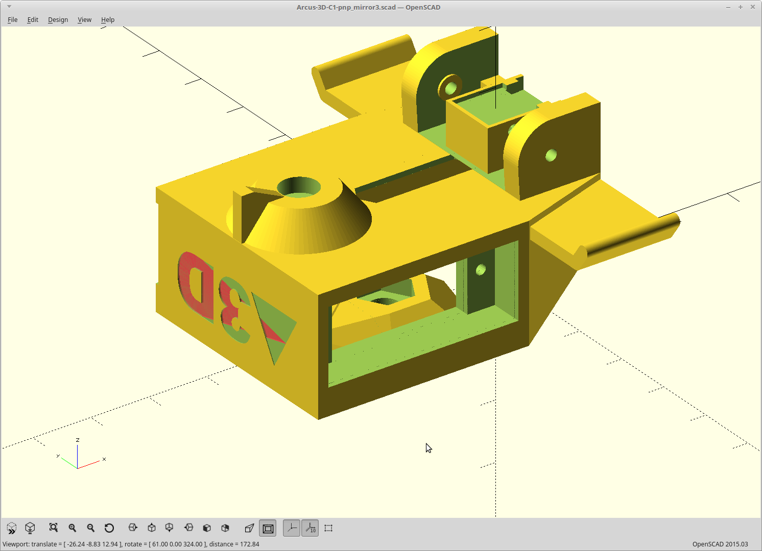
09/26/2018 at 00:18 • 0 commentsMade the changes to eliminate the part light ring and moved the main light ring out of the camera's FOV.
Mirror arm width was tweaked now that I don't have to clear the light ring gap. This allows for rotation of larger parts. I think I'm up to rotating 24mm parts at up to 14mm of depth now, but I'll check for sure once I have it assembled.
The end mirror is 8mm wider and 4mm taller than it was before to reflect more light onto the part.
I also updated the mask in front of the camera to be three slits with a gap, instead of a smooth 'light pipe' like it was before.
![]()
Body lost 1mm of height overall for additional board clearance, the camera mount was tweaked a little, and the light ring mount was moved down since the new ring spans the body to get out of the camera FOV.
![]()
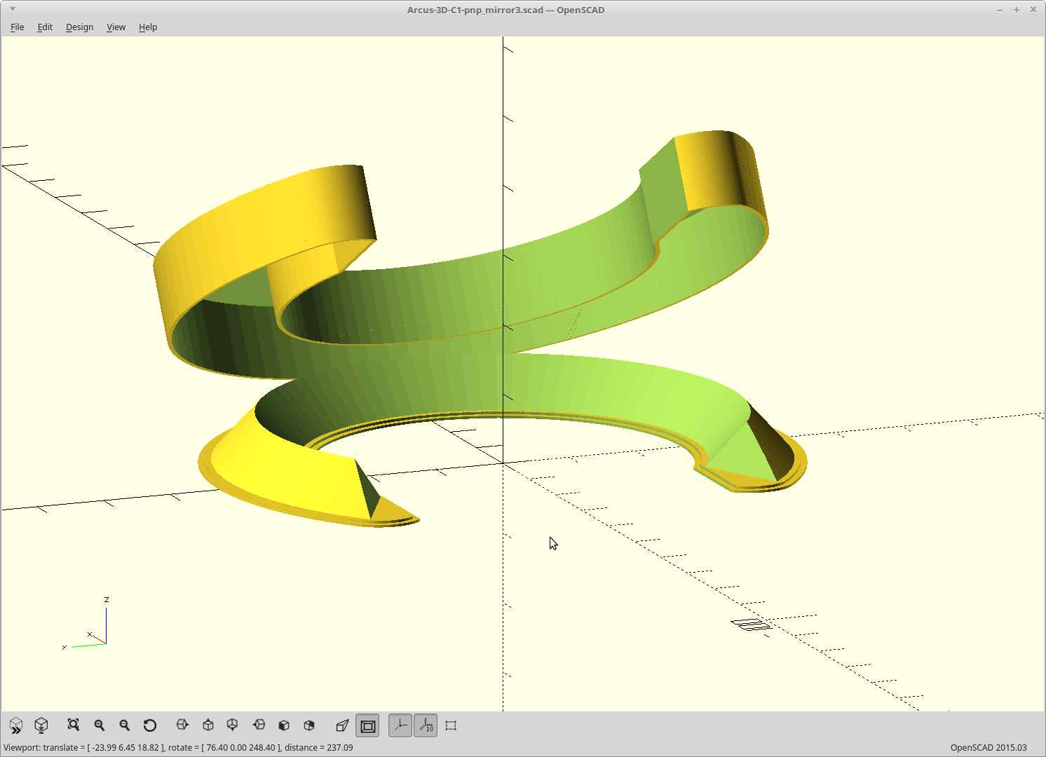
The new part light ring. It was considerably harder to design that the other rings actually. To get the rounded ends more than doubled the code size.. :)
![]()
Printing the ring and arm first, and we'll see where the camera FOV ends up before I print the body again.
-
Glare, and a plan.
09/25/2018 at 05:01 • 3 commentsIn the last iteration of the mirror arm, I precisely masked the camera with plastic near the aperture to match the FOV of the part it gets from the mirrors. I did it the wrong way.. I get a ton of glare coming in from the part ring light. I think I need just a square mask way out front, with dead space behind it. Right now it's a channel, which has the effect of giving the light something to bounce off of all the way to the camera. Changing that.
Since then though, I discovered that the main light does a pretty good job of lighting the parts with just the light bouncing off the larger mirror, except for the two ends of it which are directly in the FOV of the camera when looking up at the parts.
If I masked those bits off, or perhaps added the ability to turn those bits off, then the light bouncing off the bigger mirror will be enough to light the part and be completely outside the FOV of the camera.
I'm going to explore that, and probably make the second mirror larger to enhance the effect. Since I can ditch the part light ring then, I could go 2x the mirror size and still be at the same weight.
One issue here is I have to use the same exposure, brightness, contrast well, ALL the same settings for both the down looking and up looking version of the camera. Only one thread can have control of the camera, and it doesn't look like I'll be able to switch the settings at this point (right now.) Also, I can't just use PWM to control the amount of light as the rolling shutter combined with my required 400Hz PWM frequency causes terrible banding in the images at anything other than 'full on'. I need to use 400Hz PWM, as that is how I'm able to control the servos with enough resolution to meet my rotation accuracy goal and I can only have one PWM frequency (without breaking down and coding just that for the second PRU anyway). There are circuits which amount to adding an LC filter which could solve this too and allow dimming, but at that low of frequency, the required component values are huge.
The most straightforward solution is to just strike a delicate balance of segmenting the main light ring, and using the falloff from the distance to the board, to get the same brightness for both up and down vision. Sounds like fun. :)
For the best vision results, I'm also going to need to add a mask to the nozzle and/or print the head out in black as well.
On it.
-
Well that's an annoying bug.
09/25/2018 at 01:15 • 0 commentsTo get up and running more quickly, I'm using the linuxcncrsh interface to Machinekit.
Linuxcncrsh is ancient compared the the current remote interface, but it's already plumbed up in openpnp, mostly.
Problem is I could never get it to initialize. Everything went through and responds, but when I would get to sending commands the machine would be in ESTOP.
Today I figured that out. It's a bug in linuxcncrsh itself.
SET ESTOP OFF
SET ESTOP OFF
GET ESTOP
ESTOP ON

SET ESTOP ON
SET ESTOP ON
GET ESTOP
ESTOP OFF
Huh?
Whatever you request for the estop state gets inverted.
So setting estop off actually turns it on.
I can't really blame them. I really shouldn't be using this, and it says right in the docs that it is unmaintained.
So I'm now just sending the opposite of what I want, and it seems to work. Machine homes in openpnp too. Now for the rest.
-
Tabs are source too, and stepper current.
09/24/2018 at 21:10 • 1 commentI know this. But I somehow managed to have two of my mosfet tabs touching and blew basically an entire day trying to figure out why my command to turn on one light always turned on both. The tabs were touching, so the outputs were tied together. Fixed, so I now have independent control over each light.
I also reprinted both light rings in just nylon. It's stronger that way.
Lastly, something is going on with my stepper drivers. They don't work above 1.2A reliably anymore.
I was losing steps while homing sometimes, so I went all the way down to 100mm/sec max velocity and 800mm/sec2 acceleration, and the problem persisted. I replaced my bypass caps, which seemed to help as they were definately borderline... minimum value and running at 14v for a 16v rated cap. Problem still happened, just a little less often.
Turned up the current, problem got worse. Turned the current down from 1.6A to 1.2A and the problem went away. Moves faster than at the higher current.
The drivers aren't hot. The steppers are a little warm at 1.6A, but they are rated at 2A and never exceed 60C running at 1.6A, so that should be fine. (they start to degrade at about 80C).
I checked the power rail for dips, and my ground rail for a good stable logic level. All good.
I don't get it. I'm running them at 1.2A for now.
-
Little fish.
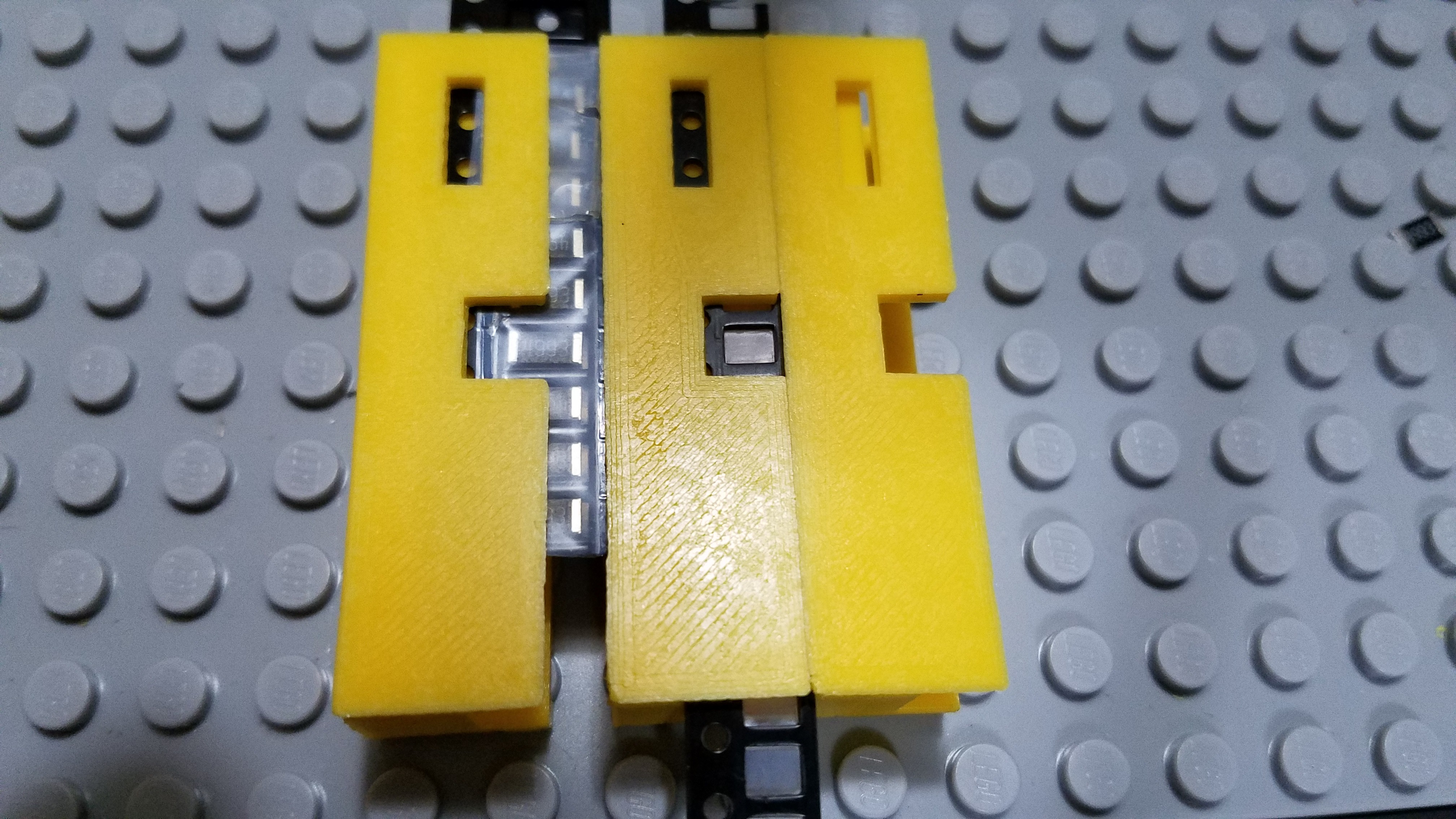
09/23/2018 at 03:12 • 2 commentsMade some updates to the Lego compatible drag feeder and printed out enough of them so you can see how it works.
![]()
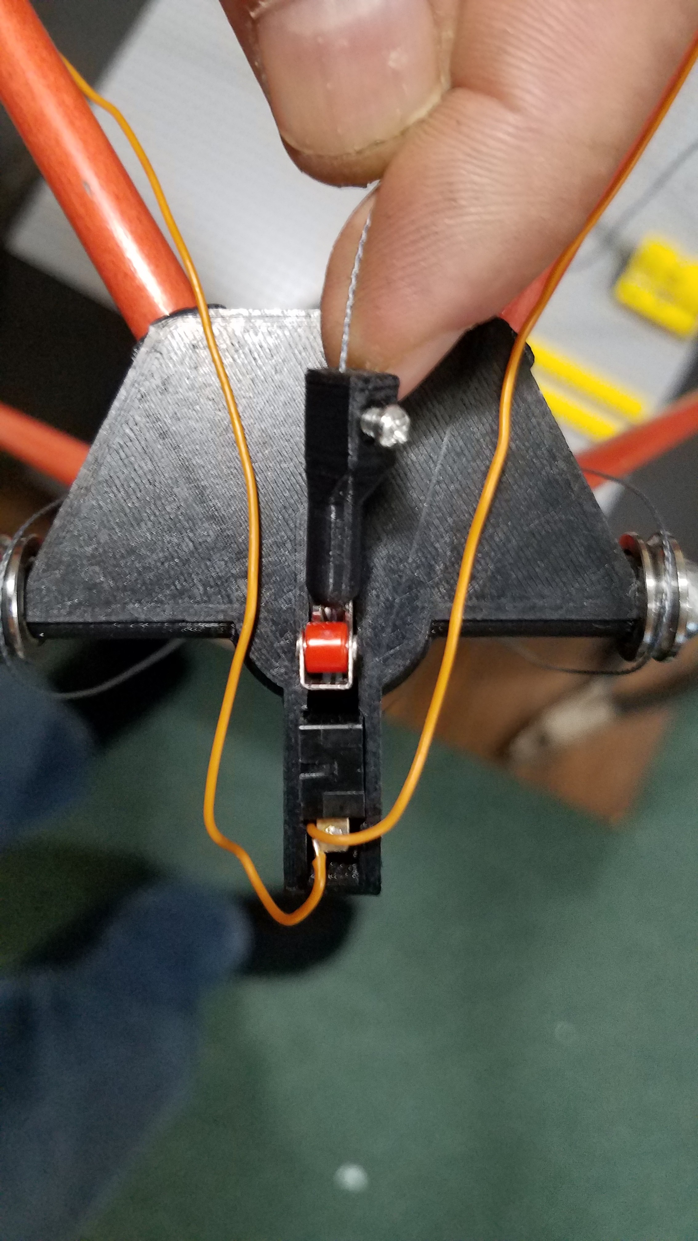
Made a couple iterations on some new endstops. I had a design which worked perfectly well, but after printing them out, I ended up redesigning them to be a lot less 'phallic'. You'll have to trust me on this one.
![]()
Reprinted the upper corner joints with more depth, and a more tuned fit for the rods.
Reworked the head wiring harness so it's cleaner and half as long.
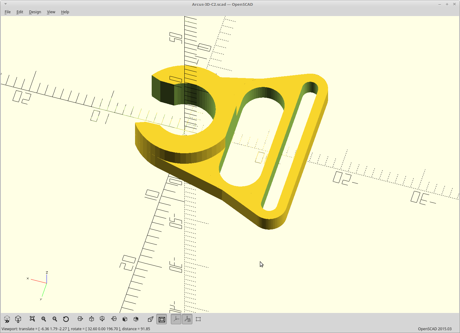
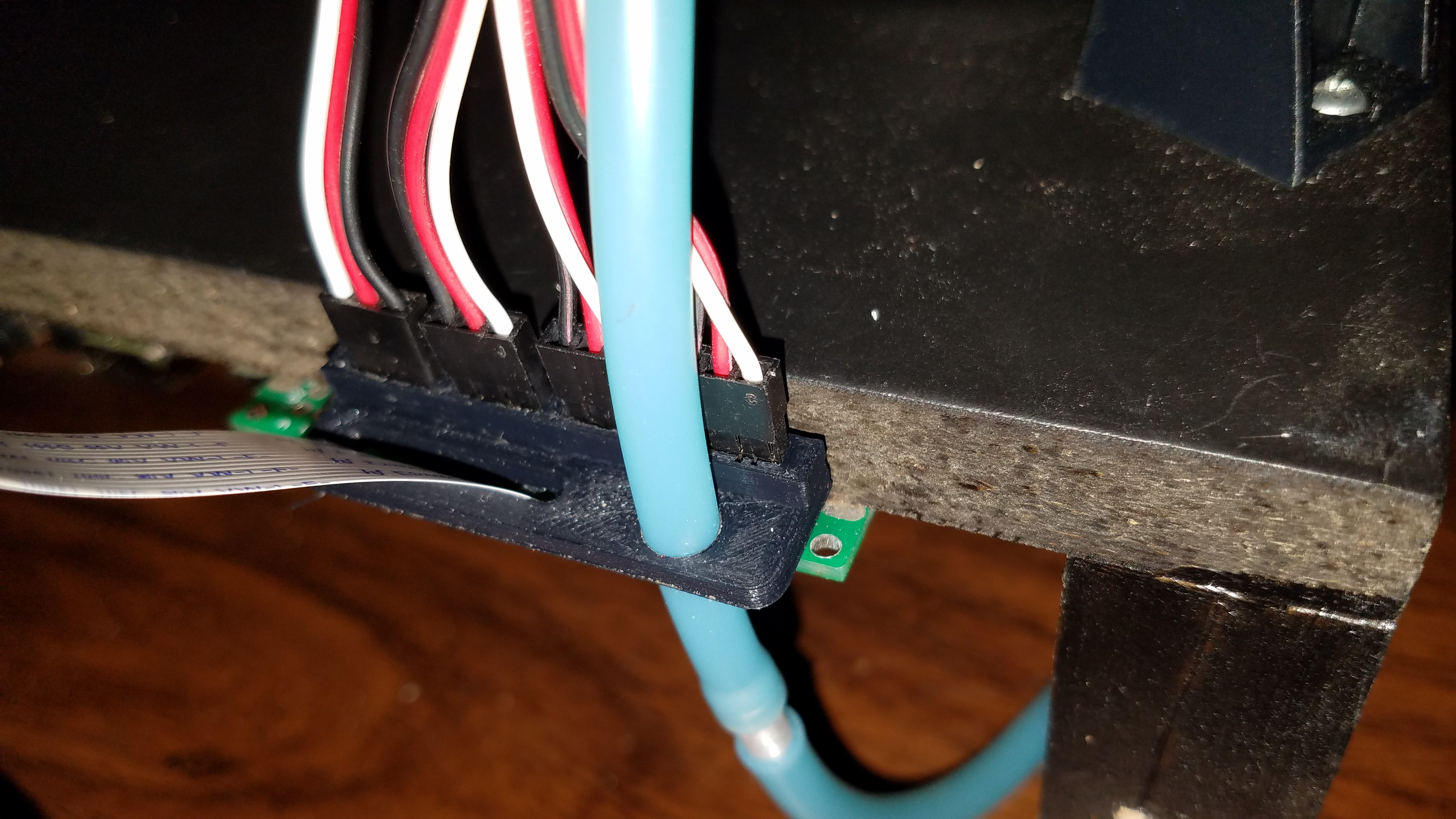
Cleaned up the wiring routing by designing and printing some purpose built cable clips. I'm tired of cutting zip ties and holding the ribbon with rubber bands.
![]()
Made a printed collar which holds the servo cable ends and routes the ribbon and air line. Now I can't accidentally plug them in out of order and don't need to resort to color coding them. I have 3.3v, 5v, 12v, ground, and Beaglebone pins directly connected there. Getting a plug out of order would definitely destroy something.
![]()
![]()
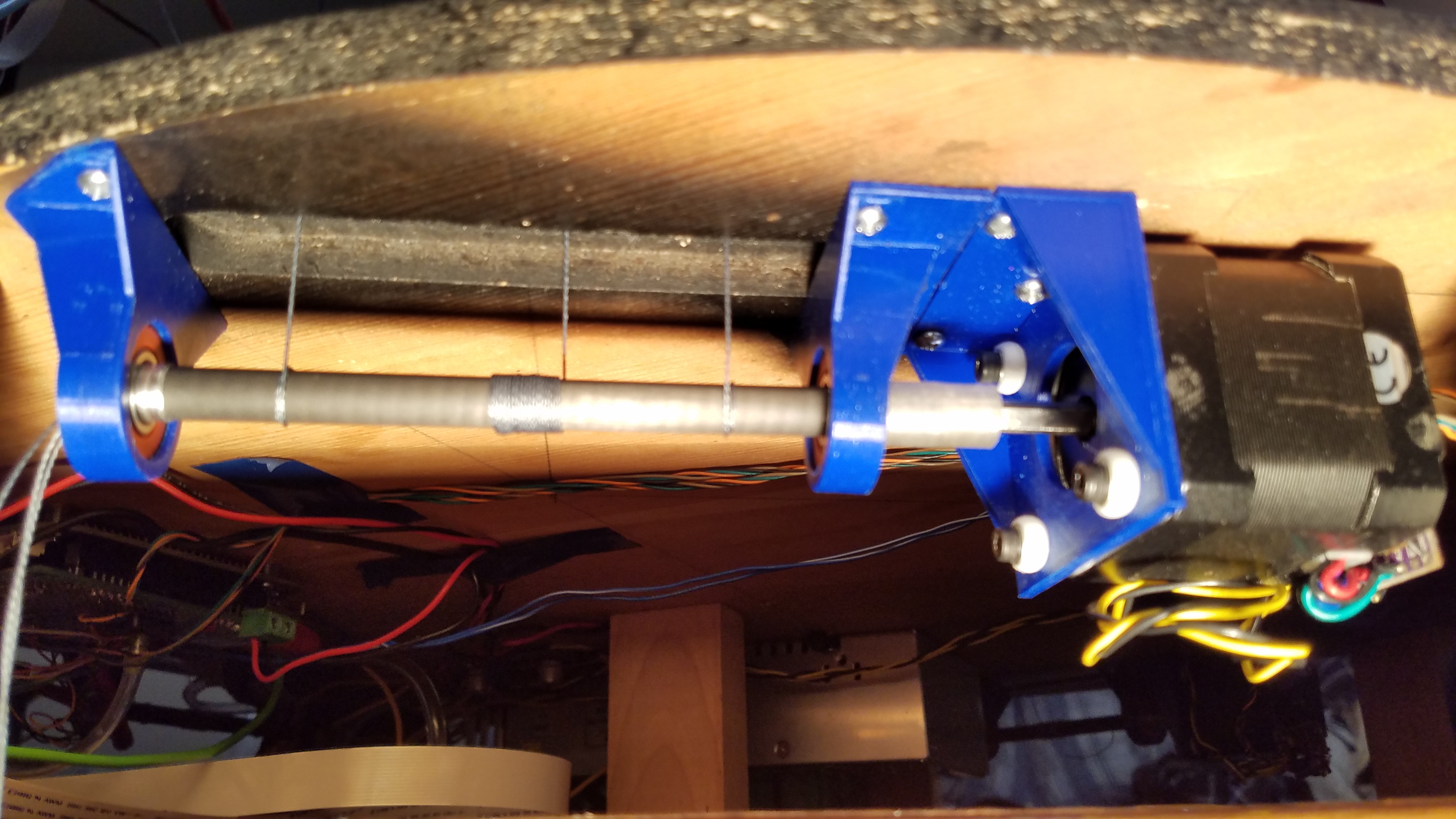
Reworked the drive spools, using some of the carbon fiber rod I had left over from the push rod. Also figured out the perfect way to make up the difference between my bearing ID and my shaft OD, which is about 0.2mm. Wraps of AL foil. Took about 8. This also lets me put the knots for that end of the cables inside the spool rod now, and tie those knots later on.
![]()
Sweet.
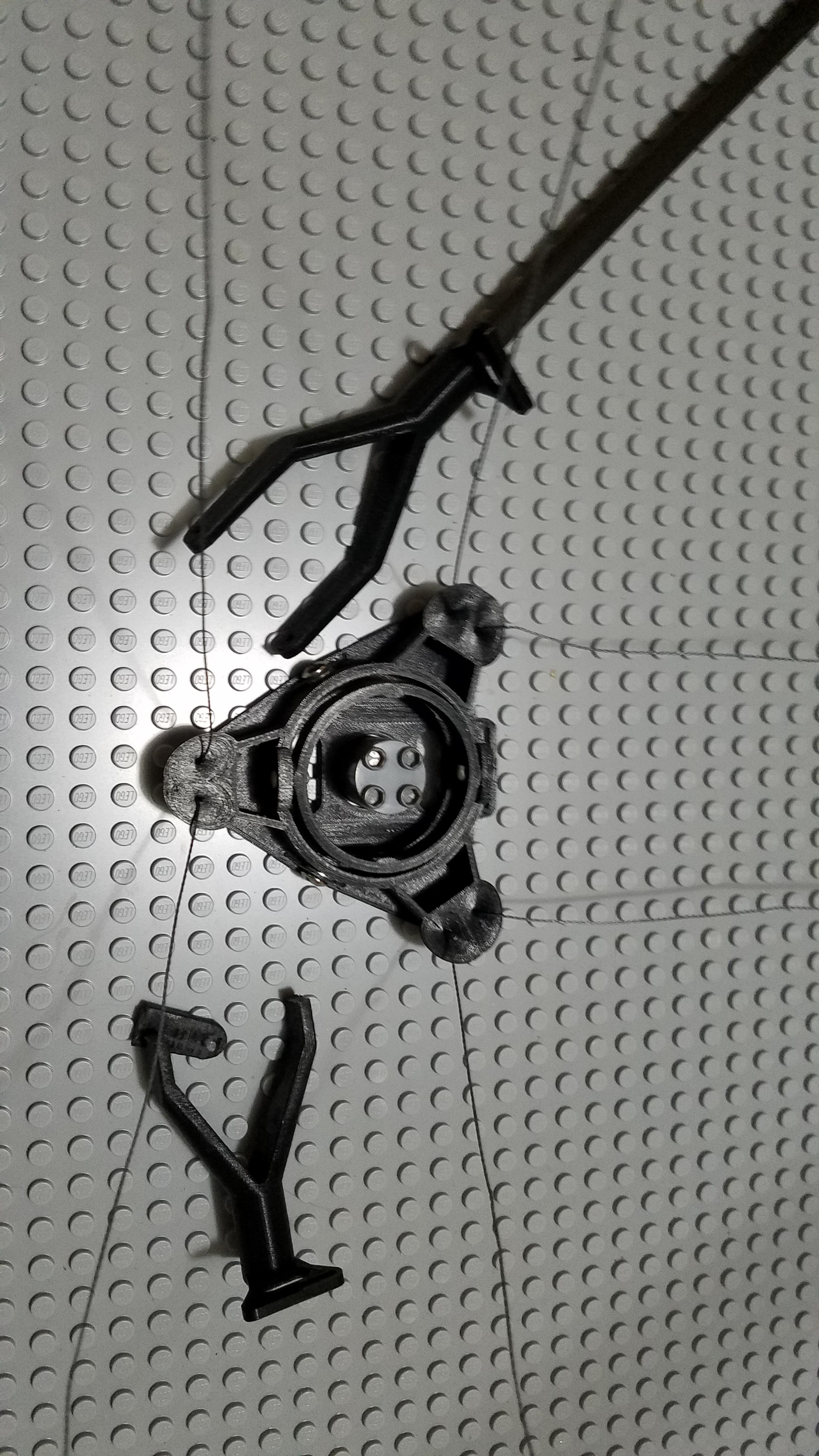
Broke the end effector while working on the spool rods when I turned the base over and crushed the joint. It only is designed for a straight on load. Reprinted.
![]()
Assembling.
-
Head assembly - Mechanical
09/18/2018 at 21:55 • 2 commentsI believe I'm done with messing with the head.
Today I did a video of the current parts and assembled them, in 10 minutes.
So here, I will answer the questions this will generate:
No, I don't have a good supplier for the brass bits yet. Everything I've found ready made for Luer lock fittings in metal, with a known ID, is huge and very expensive. If you are ok with plastic and no ESD protection for your parts, then you can just clip the end off a 10ml syringe, put a bit of heat shrink on the stainless tube, and push it on.
Yes, the right angle drive achieves the target 1.5 degree accuracy across the scale. No, it doesn't go the full 360. It now maxes out at around 355 degrees.
The plastic gears, and hypodermic tubing specifications will be linked here when I have it placing parts, which is also when I will post the final design files to Github.
<EDIT> I mentioned in the video I would do another one about aligning the optics. Well unfortunately, they were perfect as is and didn't need alignment and so got glued in immediately. :) So no video for now, and I'm moving on to bigger fish. </EDIT>
-
Think outside the cylinder.
09/17/2018 at 18:41 • 0 commentsThe modifications cleared the end effector, but now would have intersected with the cables at the back of the build area. Bah.
The new solution now squashes the part light ring down from a circle to an ellipse.
I've been stuck in thinking it could only be a cylinder from the 'light intensity falls off as square of the distance' thingy, but then again, I'm also then putting more elements in the same space due to the increased circumference. It will probably all even out.
![]()
The diameter of the ring is all old math, and was based on even multiples of the segment length for the light strip fitting the inner circumference. I hope that scales like I think it does.
It may also bring the edge of the ring into the FOV of the camera, which may cause me to need to move it back closer to the camera to kill the glare.
Trying it.
Printing.
Arcus-3D-P1 - Pick and Place for 3D printers
Open source, mostly 3D printable, lightweight pick and place head for a standard groove mount