MasterOfNull
-
Clearance Clarence.
09/17/2018 at 01:20 • 0 commentsMy mirror arm modifications failed to clear the end effector pulleys. These things will happen now that I have the motion platform and the P1 split into projects, and re-used the same global variables in both, so I can't just import one into the other. Ooops.
I have moved the virtual pulleys up to their 'ideal' location on the same plane as the center of the pushrod gimbal.
![]()
It's now half a gram heavier, but prints faster. Go figure.
Printing... again.
<EDIT> I needed 1mm more, but I'm not willing to modify the end effector any more to get it.
Moved the mounting point on the head. Printing that again..
</EDIT>
-
Burn baby burn.
09/16/2018 at 19:00 • 0 commentsNoticed as I was assembling the new main light ring in ABS that the edge had lifted and it was a little warped, and the 0.3mm single wall print was a little too thin for my comfort. I changed it to two wall and reprinted.
I also noticed if I run the ABS as the absolute top of its heat range, like 275C, I get a flat black finish instead of more glossy. Hey... I can use that.
So I reprinted the part light ring like that. It is there to keep the light from hitting the mirror directly, so a flat finish is good.
![]()
-
Reprint, aka, the chance to change everything.
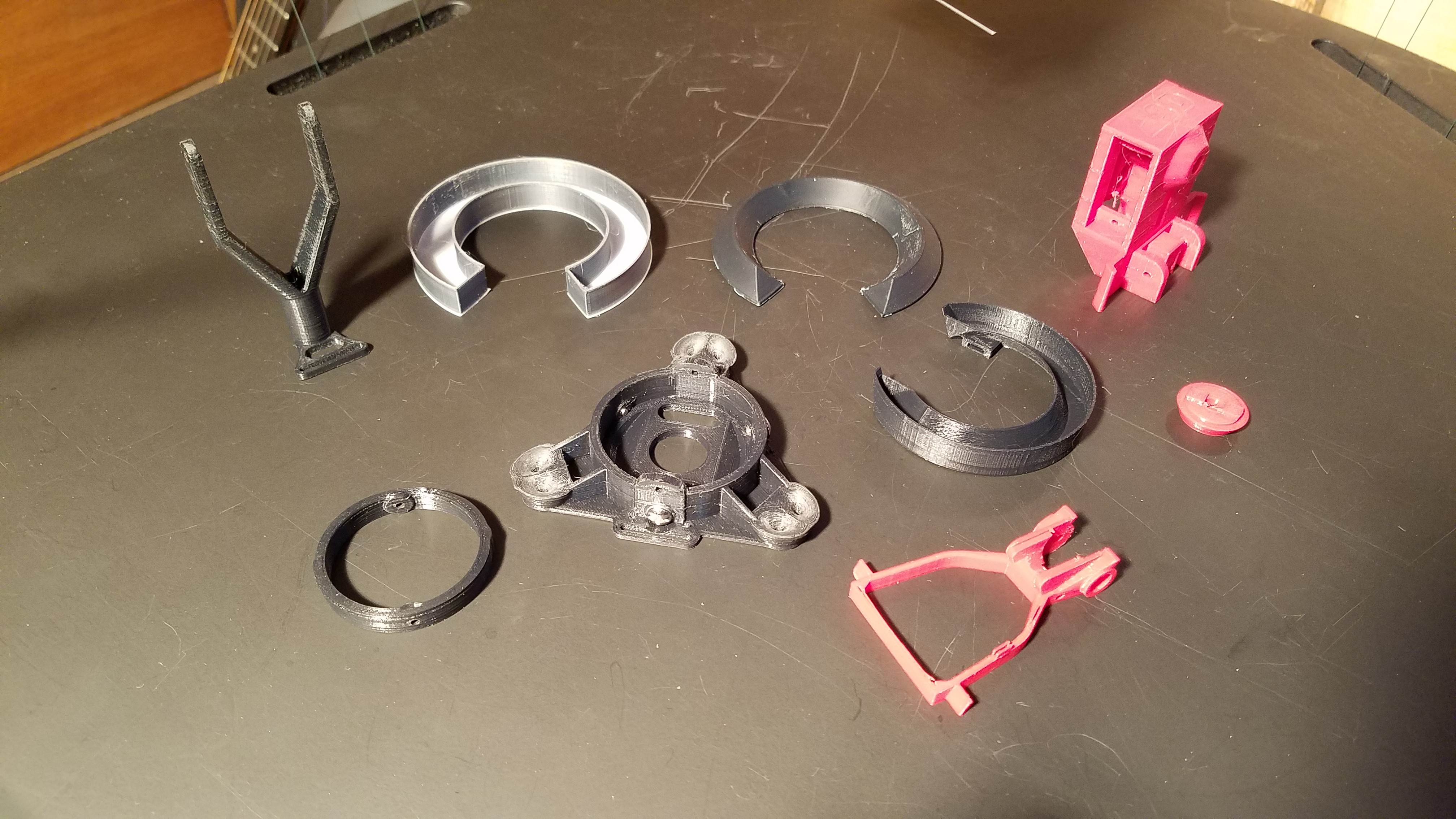
09/15/2018 at 02:02 • 0 commentsI've been modifying the source as I've been moving between parts to tweak things. There was the distinct possibility I introduced incompatible elements in doing this. Since I had a couple new parts to print anyway, I decided to reprint everything and finalize some things I've been meaning to do.
- The end effector changes already happened a few days ago, and that moved the leveling to the side and added the ribbon cable run.
- The pick and place head got some reinforcement around the groove mount. I found that if I tightened the groove mount down hard, I could distort the body to the point that the spring on the nozzle would get bound up and not slide. Fixed. I also increased the possible mounting range for the rotation servo mount, and fine tuned the Pi camera mount to self center better.
- The push rod end now has a ribbon cable slot also, the servo plugs will now actually fit through the other holes without melting it first, and I tweaked the math so I can scale it a lot better. There was an anomaly while printing the hinge area. I was watching, so I saved the print by turning down the temp a little and slowing things down. It is now a little grungy from having to sand down the mess in that area, but its strong and will work so I'm keeping it..
- The mirror arm had the light ring mount moved out a little further to clear my '180 degrees from where I planned for it' end effector, some new channels for nicer wiring added, and some additional stiffening added where the servo drives it.
- The part light ring got lighter, and I tweaked the mounting tabs to better center the light. Well that's confusing...
- The main light ring needed to be reworked. I have been running the main light much more than would be used normally... like on for hours at a time, while working on this. The PLA version was not up to that task and got squishy
So... the main light ring base is now ABS, and the main light ring diffuser is now mixed material. I didn't have any black nylon, so I just mixed in 30% black ABS into my translucent nylon. Worked. Angel hair stringies while printing. Kinda neat.
The rest of the new parts.
![]()
Now to rebuild it all.
-
The wonderful simplicity of Metric hardware.
09/14/2018 at 15:29 • 0 commentsI've come to notice some nice design patterns while building parts to work with Metric hardware, and I thought I would share.
Simple stuff, but it ends up meaning I need to keep less stuff in my brain while doing it. That is usually a good thing.
Size as used here is just the M number of the part, such as M3, M4. Size is expressed as a diameter, with most OpenSCAD operations using radius, so <dia>/2.
Clearance as used here is always 0.2mm, and that number came to be to allow over-extruding while printing to not affect the fit of the final parts.
- Through holes bolt sizes are just <size> + <clearance>. So a cylinder to subtract for a bolt hole is:
cylinder(r=(size+clearance)/2,center=true); - Pan heads are always 2*<size> + <clearance> for diameter, and <size> for height. So a cylinder to subtract to flush fit the head of a bolt would be:
cylinder(r=size+clearance/2,h=size,center=true); - Encapsulating a nut or bolt head is just as easy. Nuts are the same dimensions as pan heads, but you limit the cylinder to 6 facets. The cylinder with 6 facets still has its vertices on the ideal cylinder, but the flats end up moving in the same as a nut. So a cylinder to subtract to create a captive nut is just:
cylinder(r=size+clearance/2,h=size,$fn=6,center=true); - Threaded holes are <size> *0.9. So a cylinder to accept directly threading in a bolt is just:
cylinder(r=size*0.9/2,center=true);
That's it. Four simple rules and can you can use any metric hardware without measuring. I've never actually looked up if there is a specification which matches these observations, but so far so good.
- Through holes bolt sizes are just <size> + <clearance>. So a cylinder to subtract for a bolt hole is:
-
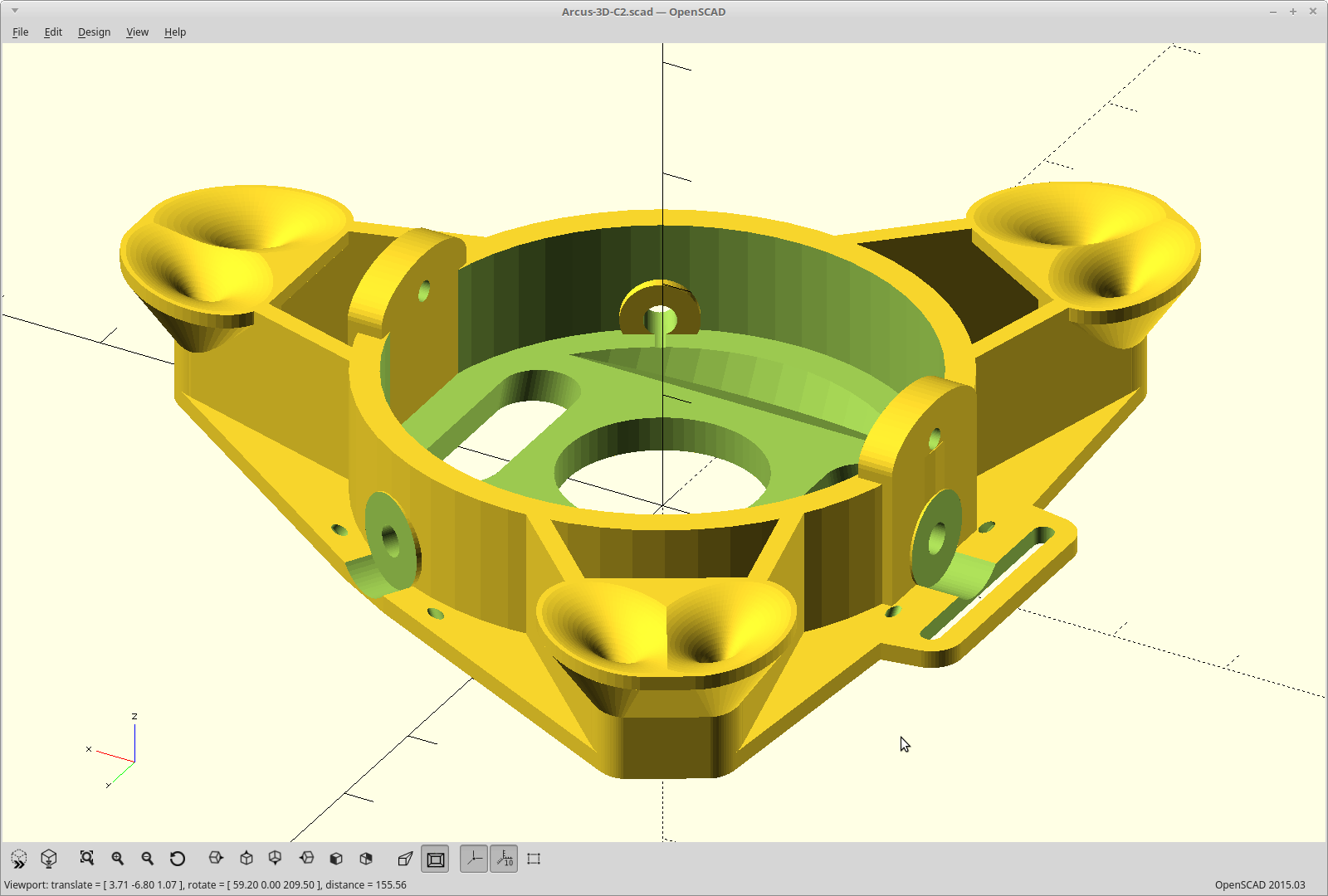
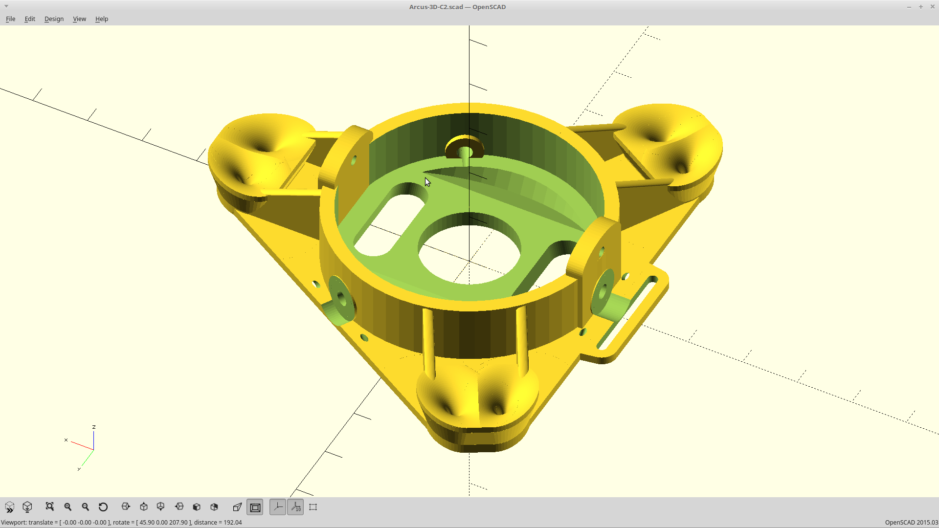
End effector tweaks.
09/13/2018 at 22:16 • 0 commentsI've been slamming the P1 head into the bed on a regular basis while I work on implementing motion. Unfortunately I need the vision on the head for some things, so not a lot of choice here.
This has had the maddening tendency to throw off the leveling when the impact is off center. My leveling screws only have so much pull before the cable slips. Probably a good thing, or I would definitely be breaking stuff as I've turned the stepper current back up a bit. I needed to. At the edges of the build area with the head attached, I was starting to lose steps during > 400mm/sec rapids due to the increased mass.
To this end, I've relocated the leveling screws to the side of the end effector, where I can get at them while the head is still attached.
I also lowered the gimbal hinge point and raised the virtual pulley. The closer they are to planar, the better. And... while I was at it I made a switch to enable/disable the blower mount/add a cable run for the Pi camera ribbon cable
![]()
Printing, but this is a long one. Need a small nozzle and low layer height to get the virtual pulleys to be smooth and accurate (and my first print failed on the hinge in the last 5 min) ARGH.
-
Coordinated rotation.
09/10/2018 at 10:38 • 0 commentsModifying and rebuilding tripodkins lets me do coordinated rotation now.
This actually slows down the mirror flip, to match the plan instead of being 'as fast as it can go' so I probably don't actually want that, but I do want part rotation to be coordinated.
That will allow the command to return when the motion is actually complete according to the planner, and give me fine control over speed and acceleration.
-
Hats.
09/09/2018 at 23:19 • 0 commentsWell it seems I definitely have my software developer hat back on now, so I'm going to run with it. I hope I don't lose my hat.
Updated the BBG in prep for setting up my build environment, which broke Machinekit. I'm bailing again, and starting over now with a fresh disk image about 1.5 years newer than what I was running. When I worked on that image last, Stretch was brand new and I had to do all sorts of nonsense to get it to work. Undoing that is likely more work than just starting over. To that end, I've backed up my Machinekit config thus far here.
<EDIT> Up and running on a new image, minus the updated kinematics. That was relatively painless. I now *have* to recompile tripodkins though, as my previously compiled .so for itripodkins (inverted) doesn't work anymore. So now my Z axis is upside down as tripodkins seems to ignore my negative HOME position, and so it doesn't flip the math on it's own.
</EDIT>
<EDIT_2:> Ok... Hats off to the Machinekit folks. Realized it's all setup to cross compile right from the git repo, using docker. That's probably what I did before and forgot about it. Make a fork, made my changes, and ran the docker build using
scripts/build_docker -t armhf_9 -c deb
Thanks to being able to use my room heater of an i7, less than 5 minutes later I had two .deb packages.
I ignored those and went looking for the 'itripodkins.so' file I just built, and found it in machinekit/rtlib/modules/. That compile would have taken at least an hour using the BBG processor.
I copied that into my freshly built image at /usr/lib/linuxcnc/rt-preempt/, and it works. I now have the rc servo for part rotation as a proper axis, with limits, scale compensation, and the trajectory planner knowing exactly how fast things can move.
Made a script to do the rest of the needed configuration. I think I'll package up my own image from this.
</EDIT_2>
In other news, I think I've found a nice way to split the video stream going into Openpnp using Gstreamer vfl2sink, and the vfl2loopback kernel module. Right now I can setup either the top camera, or the bottom camera in Openpnp, but not both. They both expect exclusive access to the camera and since my implementation has only one camera... uh... that won't work.. but this might. If all goes well, it will even use DMA copies to do the split so basically no CPU penalty. I'm psyched, but it's still early. :)
-
Round and round.
09/09/2018 at 08:17 • 0 commentsPart rotation responds to joint position commands, but won't work as the C axis. The reason is simple.
Tripod kinematics in Machinekit doesn't pass it through, and worse... explicitly sets the ABC axis position to 0.
I modified the source to fix it. Took like 2 minutes. But now I've now blown most of the night trying to get my build environment set back up for cross compiling Machinekit for the Debian Stretch armhf flavor which runs on the BBG.
It doesn't work.. I didn't isolate the libraries properly, so I'm pulling in wrong versions of stuff.
So I just bailed and went the other route of just compiling it locally on the BBG, but for the life of me I can't get the my laptop connection shared out to it over USB. I've done this literally hundreds of times, but my scripts/the old steps don't work anymore and I have no idea why. I must have updated something and broke it.
EDIT: Tried the same steps on the Pi, and they work fine. Going that 'route'... I crack myself up.. Now it's just a matter if I can fit the entire build environment and a swap file in the 1 gig I have remaining on the onboard flash.
I could always just resort to plugging it into my micro-router, but now this is personal.
However, I have figured out all my Machinekit related issues:
- Mirror flips as a digital pin toggle
- Rotation works and is a proper axis (minus tripodkins needing to be recompiled)
- The solenoid works as a digital pin toggle.
- PWM for the lights is an analog pin setting.
Got to play with the camera, and discovered I really need to split my lights to run on two seperate mosfets. The glare from running both lights in parallel completely overwhelms the bottom vision. I'm redesigning the flippy part of the light too a bit while I'm at it.
Here is a little video of most of what works now, with me manually putting in the appropriate M and G codes, and manually stepping the joint position for part rotation in 10 degree increments. I'm still about half a degree off on my scaling for the negative side of the C axis rotation, and I believe my limit settings also need to be scaled now as I can't go a full 180 anymore. For a first try though here, it was actually pretty close.
I also ended up replacing my dirt cheap mirror flip servo with a proper one. I tried to design the mirror arm to tolerate a pretty wide range of error and still stop centered, but what can I say. The knock-off servos just suck that badly and the brand name ones behave a whole lot better. They were ok at 50Hz update rate, but when I switched to 400Hz, they got worse.
I think I'm going to relegate the knockoffs to just powering the tape feeders, where they just do the grunt work of pulling back the lever and no accuracy is required at all.
-
Keep away from open flame.
09/06/2018 at 22:57 • 0 commentsI was mounting the head and putting on a bit of heat-shrink when I got too close to one of the lines. Oops.
So much for seeing if it would stay calibrated when I moved it to the Makerspace tonight.
A little bit of code, an hour drive, and now replacing a line are what stand between me and a video for you all.
EDIT: Ok.. a little more than a little bit of code. My digital pins within Machinekit are not cooperating, so I can't control the mirror or light from within Openpnp. Ah well.
Recorded where I'm at anyway.
-
I know a secret..
09/06/2018 at 18:44 • 0 commentsAnd of course, I'll share.
The tripod kinematics have been a PITA with a whole lot of trial and error with determining how to tune everything.
But.. today it dawned on me how exactly how I am supposed to do it.
Moving the endstops has no effect with correcting curvature of the X-Y plane. They do allow you to level the build plane though. Home the machine. if the end effector is not in the center when homed, move the endstops until it is. That will get you 99% of the way there for leveling. The last 1% you can get by measuring the height from the build plane a given distance both towards and away from an axis.
Moving the HOME position itself, vertically at least, also has zero effect on correcting the curvature of the X-Y plane. It just affects what your G92 offsets end up being.
The real secret is this.
- Home the machine, then home it again. The first homing gets the lines in the ballpark, but the endstops could still be higher/lower angle when they engage the switch at that point. The second homing is always perfect as you are starting from a known height.
- Measure the height at center. I do this with a block, moving the end effector in coordinated mode to match it's height. Then move out part way to the edge of the build area, I do this with G0 Y120. Measure the height again. If the end effector is higher at the edge, reduce your TRIPOD_* values. This is assuming of course you have already leveled the build area! If not, repeat the measurement at G0 Y-120 and then you will know.
- Once you have the machine tracking a flat plane, then equally adjust the SCALE on your AXIS to correct for the dimensional distortion you may have introduced in step 2.
It now tracks perfectly flat throughout the build area. Whew...
This has also uncovered an issue though. The virtual pulley profile needs some tweaking. At the top limits, near the edge of the build area, the effector starts to tilt away from the center slightly. That is also where the virtual pulley is the most 'engaged'. Luckily though, for this project, it won't matter as everything it will be doing is at the bottom of travel.
Arcus-3D-P1 - Pick and Place for 3D printers
Open source, mostly 3D printable, lightweight pick and place head for a standard groove mount