Artem Kashkanov
-
Experimental dekatron cell assembly
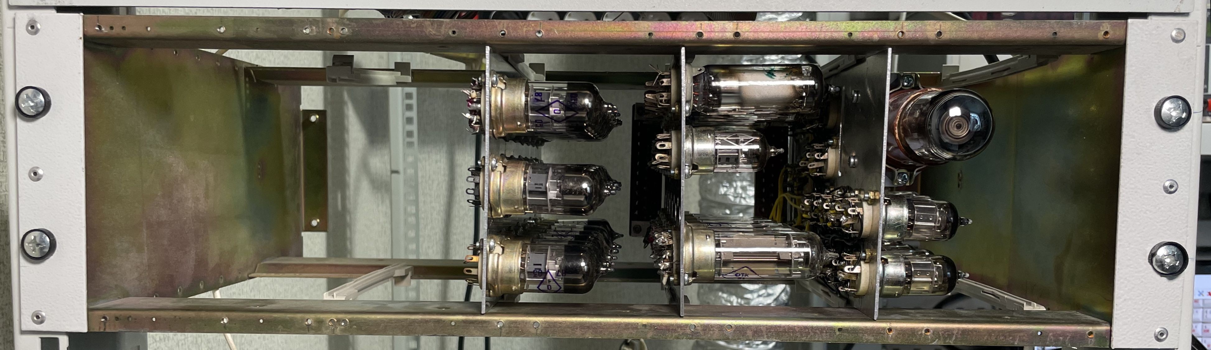
04/11/2022 at 18:48 • 0 commentsI have a good assembly progress in experimental dekatron cell. All modules are already installed into 3U crate. Today I added connector holders - and now can start wiring it up. I also wait for new sockets to add them on unit 3.
![]()
-
Experimental dekatron cell get two more tube plates
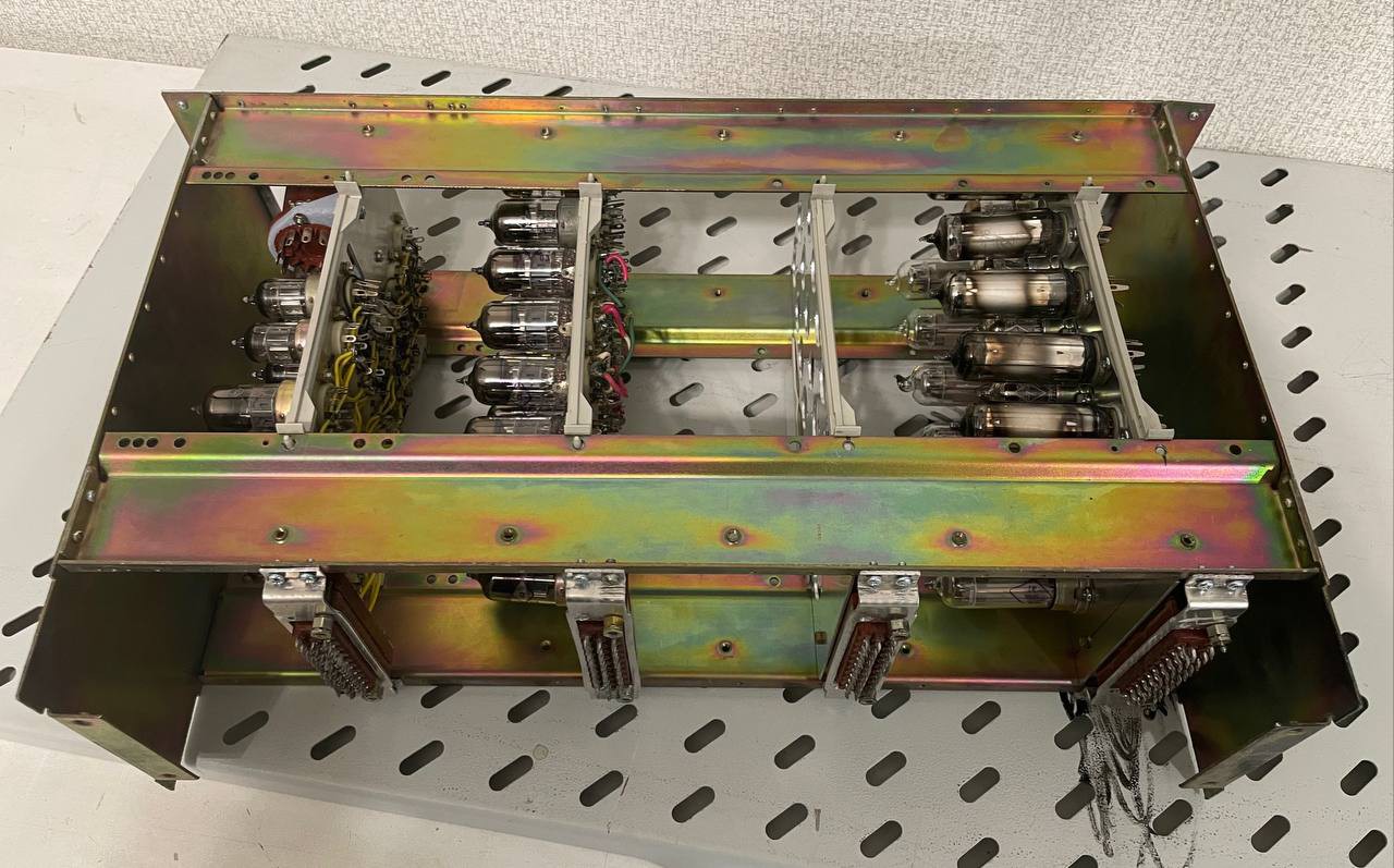
04/10/2022 at 08:27 • 0 commentsI made two more tube plates for experimental dekatron cell.
![]()
From left to right
- BCD-to-BIN coder unit
- 6-channel voltage stabilizer unit
- Dekatron unit with BIN-to-BCD coder and carry output
- [Required to build] Write amplifiers and level shifters unit
![]()
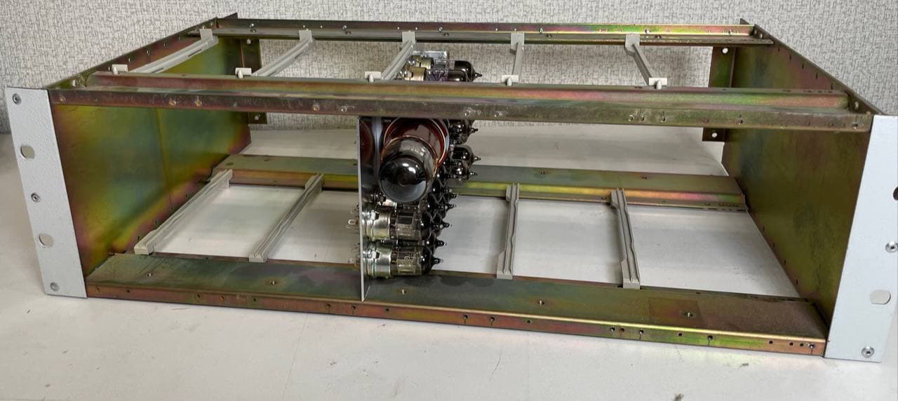
Now, 3U crate look like this. But I need to re-drill the rail holes to give the modules more space between each other. On the back, coolers, transformers and rectifiers would be added.
-
Experimental Dekatron cell became more real
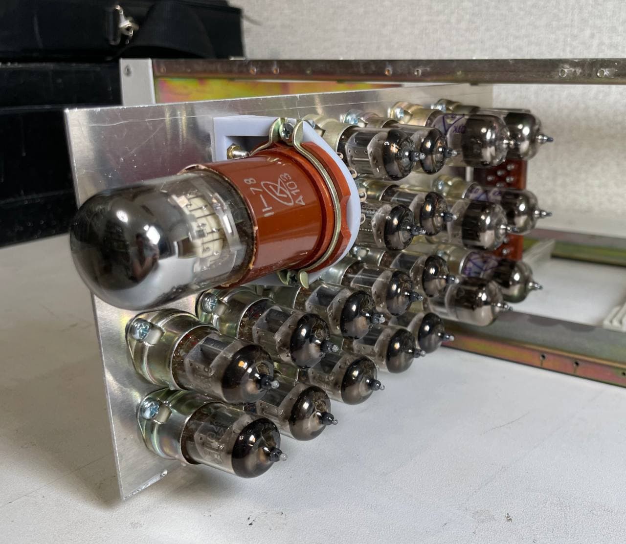
02/21/2022 at 12:49 • 0 commentsI start building process of experimental dekatron cell. The idea is to develop and debug Read and Write control circuits for dekatron. All other computer stuff can be just created from regular logic elements, but not this one. Voltage difference is up to 900V, about 6 different voltages and cray amount of tubes.
![]()
I selected 3D-wiring because need to develop schema first. So this unit is for debug purposes only. Further 17 dekatron unit would be PCB-based with subminiature tubes.
![]()
This is how future 3U block will look like. Lately I'll add other modules, PSU, coolers and so on.
-
Experimental Dekatron Cell
02/17/2022 at 09:16 • 0 comments![]()
For my Dekatron-based vacuum tube computer I need to build 4 counters with 17 dekatrons with few deviations between counters:
IP( Instruction Pointer) counter - generates address of current instruction. Has 6 dekatrons so can handle regions from 0 to 999999. Doesn't require any write operations but has full Reading block. Also set to 0 required
LOOP Counter - Collect current loop level for loop lookup process. We can do IP++ or IP-- so need to scroll instruction chain like +++[+[+[+]++ with counting current level of skipped loop. Doesn't require any write or read operations. Set to 0 required and Zero output requested.
AP (Address pointer) counter - contain 5 dekatrons and handle from 0 to 29999 cells - as Brainfuck has 30k cells. Doesn't require full Write block but need set to 0 for all block and set to 2 for highest dekatron. Full read block.
Data counter - contain 3 dekatrons and handle from 0 to 255. It require full write block, full read block and block with will do 0 to 255 and 255 to 0 operations carefully. So first I want to build full noval-based dekatron cell like rendered one.
This is a cell circuit without write logic.
![]()
Dekatron PCB would be look like this (but I need to update all renders as already modified the circuit).
![]()
-
Vacuum tube computer emulator: hardware
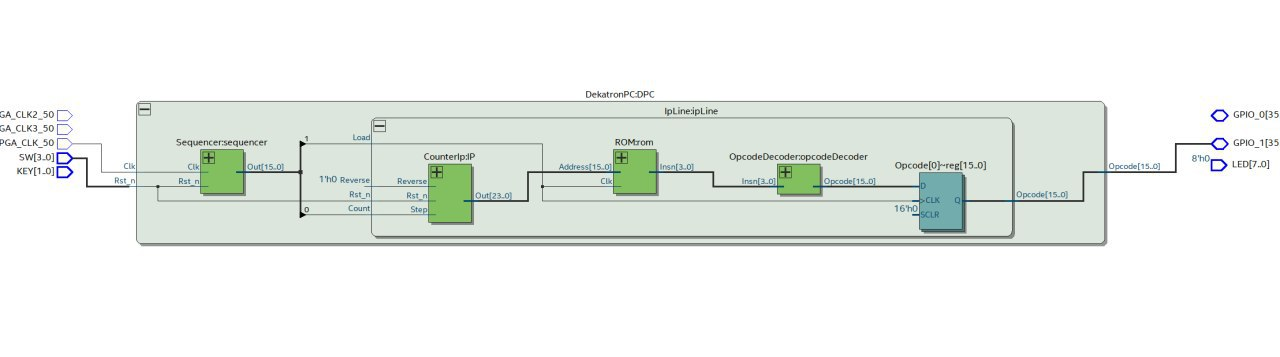
06/07/2021 at 08:20 • 0 commentsMain milestone is almost done. FPGA-based emulator became more real as before.
![]()
The idea of making emulator is to develop whole logic-level architecture of the future vacuum tube computer on Verilog.
Initially we have nothing to check the idea, but with the first physical emulation block we can "build" the computer schema, test it, debug it, improve it and we would get fully-functional computer, which can perform brainfuck programs.
After this milestone would be done, we can start assembling any computer block as physical parts. e.g. - build IP counter or opcode decoder and so on. This physical block would replace emulated parts and we would get fully functional computer again.
With replacing other emulated blocks with the physical finally we could remove emulator and would get fully functional fully-built vacuum tube computer.
Currently, emulator contain DE0 nano Soc dev board, demux I\O board for indicator part and text display, nixie display for counters and a keyboard. Further, some high-speed I\O boards would be added.
-
DekatronPC insights: Verilog model develop
04/22/2020 at 08:12 • 0 commentsI started develop the Verilog model of DekatronPC computer in order to analyze low-level schematic of all future blocks.
This model would be very useful for:
- Understand upcoming amount of work;
- Count required number of logic elements with different types
- Implement and do debugging the circuit of logic sequencer.
- Analyze performance issues, and find ways to get maximum performance.
During the first time, while no DekatronPC blocks are exit, I will use FPGA emulator to analyze correctness.
While new computer blocks will be done, I will replace emulated parts with the physical one - So just right after the first computer block become to real life - I'll already can show how it works.
Now, I'm working on instruction fetching, and loop handling code. All the code is available on the github repository
-
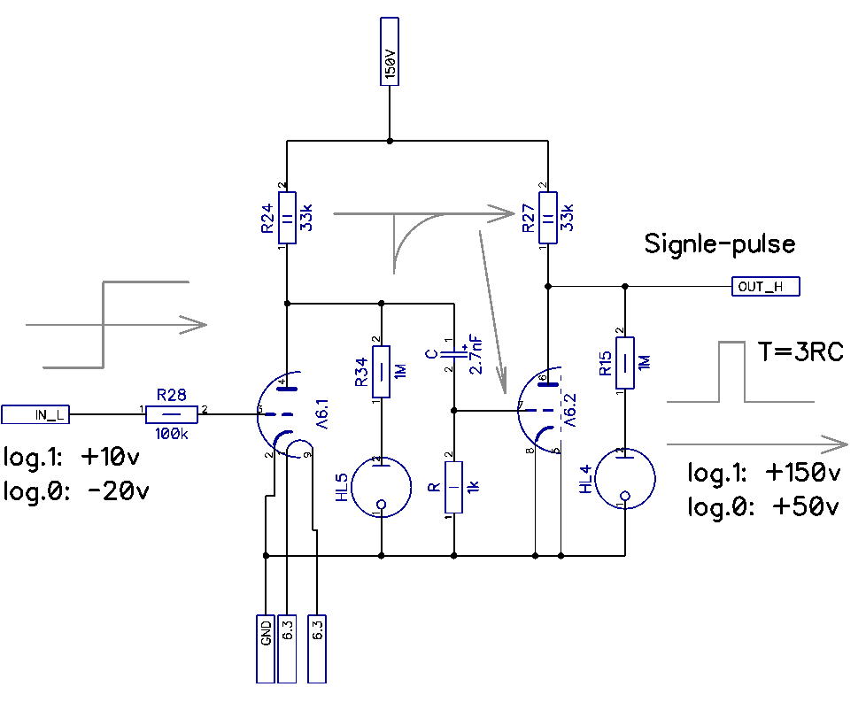
Vacuum tube test board №1. Circuits
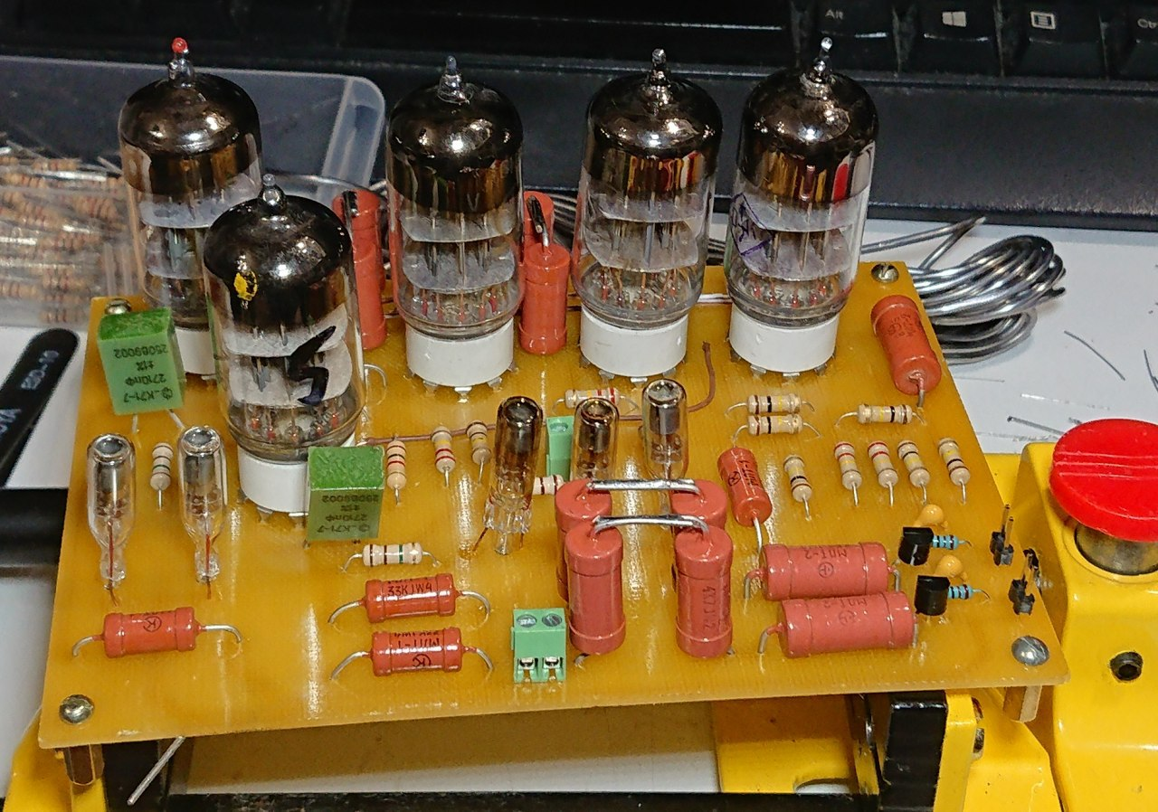
04/08/2020 at 08:04 • 0 commentsI'm done with soldering and testing test board №1.
Logic elements:
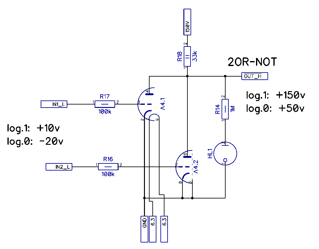
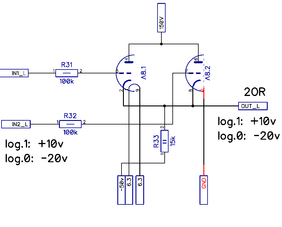
2OR, 2OR-NOT, Two rising-front Single-pulse circuits and High-level to low-level logic ranges converter.
Circuits.
-
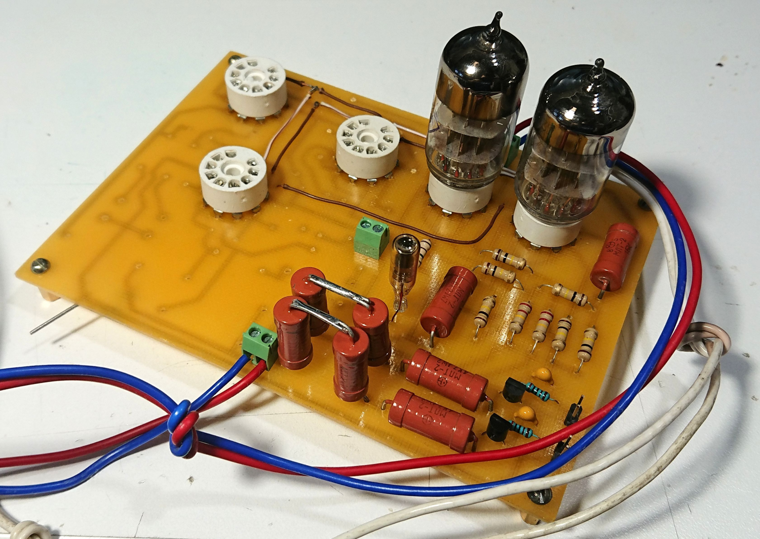
I Started assembly of vacuum tube logic test board
04/07/2020 at 07:54 • 0 commentsTwo schemes from IBM 650 manual - 2OR and 2OR-NOT. Stay tuned for more information about each circuit.
-
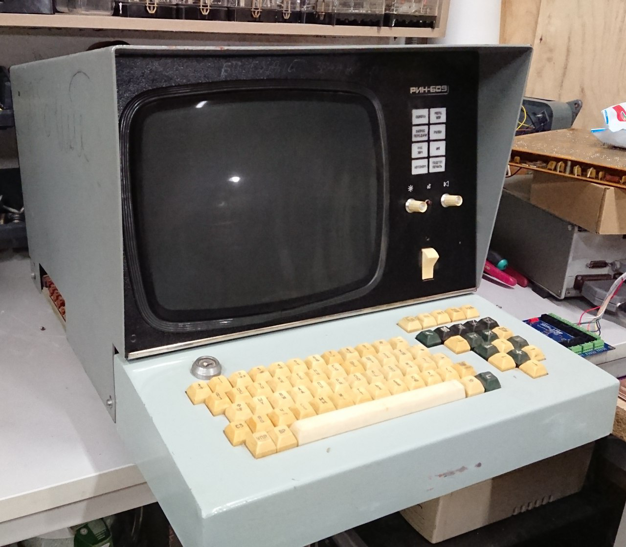
The most insane terminal for lamp computer
10/25/2019 at 07:21 • 0 commentsI received the most insane terminal for DekatronPC project. This is vector display RIN-609 with keyboard, which was used as a I/O-terminal for soviet BESM-6 and M-400 computers. Can be used instead of Videoton-340.
Mine variant goes with ferrite core memory RAM module, but next generation of this device were produces with static RAM already.
-
9-track tape recorder. Tape loading test
06/15/2019 at 18:17 • 0 commentsI tried to turn On one of two tape recorders and tried to load tape. So, it's work. Next stage is to check playing and recording modes and try to save and load data to tape.
DekatronPC
Silicon-free computer on vacuum and cold-cathode tubes with pure brainfuck instruction set